Table of Contents
Advertisement
Advertisement
Table of Contents

Subscribe to Our Youtube Channel
Related Manuals for Asus P5QL


Summary of Contents for Asus P5QL
- Page 1 P5QL...
- Page 2 Product warranty or service will not be extended if: (1) the product is repaired, modified or altered, unless such repair, modification of alteration is authorized in writing by ASUS; or (2) the serial number of the product is defaced or missing.
-
Page 3: Table Of Contents
Contents Notices ......................vi Safety information ..................vii About this guide ..................vii P5QL specifications summary ..............ix Chapter 1: Product introduction Welcome! ..................1-1 Package contents ................. 1-1 Special features ................1-1 1.3.1 Product highlights ............1-1 1.3.2 Innovative ASUS features ..........1-2 Before you proceed .............. - Page 4 2.1.1 Creating a bootable floppy disk ........2-1 2.1.2 ASUS Update utility ............2-2 2.1.3 ASUS EZ Flash 2 utility ........... 2-3 2.1.4 AFUDOS utility ..............2-4 2.1.5 ASUS CrashFree BIOS 3 utility ........2-5 BIOS setup program ..............2-6 2.2.1...
- Page 5 Boot Device Priority ............2-21 2.7.2 Boot Settings Configuration .......... 2-21 2.7.3 Security ................. 2-22 Tools menu ................. 2-24 2.8.1 ASUS EZ Flash 2 ............2-24 2.8.2 Express Gate ..............2-24 2.8.3 AI NET 2................ 2-25 Exit menu ..................2-25...
-
Page 6: Notices
Notices Federal Communications Commission Statement This device complies with Part 15 of the FCC Rules. Operation is subject to the following two conditions: • This device may not cause harmful interference, and • This device must accept any interference received including interference that may cause undesired operation. -
Page 7: Safety Information
Safety information Electrical safety • To prevent electric shock hazard, disconnect the power cable from the electric outlet before relocating the system. • When adding or removing devices to or from the system, ensure that the power cables for the devices are unplugged before the signal cables are connected. If possible, disconnect all power cables from the existing system before you add a device. - Page 8 Refer to the following sources for additional information and for product and software updates. ASUS websites The ASUS website provides updated information on ASUS hardware and software products. Refer to the ASUS contact information. Optional documentation Your product package may include optional documentation, such as warranty flyers, that may have been added by your dealer.
-
Page 9: P5Ql Specifications Summary
- 4 x 240-pin DIMM sockets support unbuffered non-ECC DDR2 1066/800/667MHz memory modules - Supports up to 16GB system memory * Refer to www.asus.com or this user manual for the Memory QVL (Qualified Vendors Lists) ** When you install a total memory of 4GB or more,... - Page 10 - Memory tuning from 667MHz to 1333MHz for DDR2 - PCI Express frequency tuning from 100MHz to 160MHz at 1MHz increment Overclocking protection: - ASUS C.P.R. (CPU Parameter Recall) Other features ASUS MyLogo 2 Rear panel ports 1 x PS/2 keyboard port...
-
Page 11: Chapter 1: Product Introduction
® The motherboard delivers a host of new features and latest technologies, making it another standout in the long line of ASUS quality motherboards! Before you start installing the motherboard, and hardware devices on it, check the items in your package with the list below. -
Page 12: Innovative Asus Features
BIOS file using a floppy disk, a USB flash disk, or the motherboard support DVD that contains the BIOS file. ASUS EZ Flash 2 ASUS EZ Flash 2 is a utility that allows you to update the BIOS without using an OS-based utility. Express Gate Express Gate is a unique OS built into the motherboard. - Page 13 AI Booster The ASUS AI Booster allows you to overclock the CPU speed in Windows environment without the hassle of booting the BIOS.
-
Page 14: Before You Proceed
ON, in sleep mode, or in soft-off mode. This is a reminder that you must shut down the system and unplug the power cable before removing or plugging in any motherboard component. The illustration below shows the location of the onboard LED. SB_PWR P5QL Standby Power Powered Off P5QL Onboard LED Chapter 1: Product introduction... -
Page 15: Motherboard Overview
Screw holes Place six screws into the holes indicated by circles to secure the motherboard to the chassis. Do not overtighten the screws! Doing so can damage the motherboard. Place this side towards the rear of the chassis P5QL ASUS P5QL... -
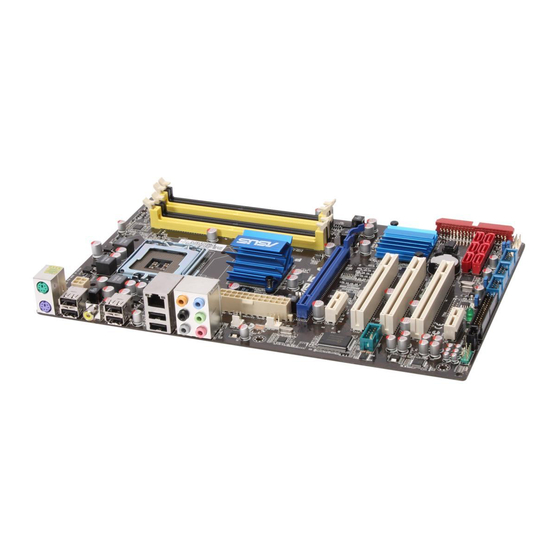
Page 16: Motherboard Layout
1.5.3 Motherboard layout 19.3cm(7.6in) PS2_USBPW56 KBMS ATX12V USB56 SPDIF_O USB34 LGA775 LAN1_USB12 AUDIO Intel ® CHA_FAN USBPW1-4 CPU_FAN PWR_FAN P5QL 8111C PCIEX16 PCIEX1_1 Super Intel ® PCI1 ICH10 COM1 PCI2 Lithium Cell BIOS CMOS Power PCI3 VT1708S PCIEX1_2 SB_PWR SATA6... -
Page 17: Central Processing Unit (Cpu)
Contact your retailer immediately if the PnP cap is missing, or if you see any damage to the PnP cap/socket contacts/motherboard components. ASUS will shoulder the cost of repair only if the damage is shipment/transit-related. • Keep the cap after installing the motherboard. ASUS will process Return Merchandise Authorization (RMA) requests only if the motherboard comes with the cap on the LGA775 socket. - Page 18 Press the load lever with your thumb Retention tab (A), then move it to the left (B) until it is released from the retention tab. To prevent damage to the socket pins, do not remove the PnP cap unless you are installing a CPU. Load lever Lift the load lever in the direction of the PnP cap...
- Page 19 To prevent contaminating the paste, DO NOT spread the paste with your finger directly. Close the load plate (A), then push the load lever (B) until it snaps into the retention tab. ASUS P5QL...
-
Page 20: Installing The Cpu Heatsink And Fan
Do not forget to connect the CPU fan connector! Hardware monitoring errors can occur if you fail to plug this CPU_FAN connector. CPU FAN PWR CPU FAN IN P5QL CPU FAN PWM P5QL CPU fan connector 1-10 Chapter 1: Product introduction... -
Page 21: Uninstalling The Cpu Heatsink And Fan
The motherboard comes with four Double Data Rate 2 (DDR2) Dual Inline Memory Modules (DIMM) sockets. The figure illustrates the location of the DDR2 DIMM sockets: Channel Sockets Channel A DIMM_A1 and DIMM_A2 Channel B DIMM_B1 and DIMM_B2 P5QL P5QL 240-pin DDR2 DIMM sockets ASUS P5QL 1-11... - Page 22 1.7.2 Memory configurations You may install 512MB, 1GB, 2GB, and 4GB unbuffered non-ECC DDR2 DIMMs into the DIMM sockets. • You may install varying memory sizes in Channel A and Channel B. The system maps the total size of the lower-sized channel for the dual-channel configuration. Any excess memory from the higher-sized channel is then mapped for the single-channel operation.
- Page 23 P5QL Motherboard Qualified Vendors Lists (QVL) DDR2-1066MHz capability DIMM support Chip Size Vendor Part No. Chip No. Brand 512MB Kingston KHX8500D2/512 Kingston Heat-Sink Package • • • 512MB Kingston KVR1066D2N7/512 Elpida E5108AJBG-1J-E • • • Kingston KHX8500D2K2/1GN Kingston Heat-Sink Package •...
- Page 24 DDR2-800MHz capability DIMM support Size Vendor Part No. Chip Brand Chip No. GEIL GB24GB6400C5DC GEIL GL2L128M88BA25AB • • • GEIL GB28GB6400C5QC GEIL GL2L128M88BA25AB • • • GEIL GX22GB6400LX GEIL Heat-Sink Package • • • GEIL GX24GB6400DC GEIL Heat-Sink Package • •...
- Page 25 • B*: Supports one pair of modules inserted into either the yellow or the black slots as one pair of Dual-channel memory configuration. • C*: Supports four modules inserted into both the yellow and black slots as two pairs of Dual-channel memory configuration. Visit the ASUS website at www.asus.com for the latest QVL. ASUS P5QL 1-15...
-
Page 26: Installing A Dimm
1.7.3 Installing a DIMM Unplug the power supply before adding or removing DIMMs or other system components. Failure to do so can cause severe damage to both the motherboard and the components. To install a DIMM: DDR2 DIMM notch Press the retaining clips outward to unlock a DDR2 DIMM socket. -
Page 27: Expansion Slots
This motherboard supports PCI Express x1 network cards, SCSI cards, and other cards that comply with the PCI Express specifications. 1.8.5 PCI Express x16 slot This motherboard supports a PCI Express x16 graphics card that complies with the PCI Express specifications. ASUS P5QL 1-17... -
Page 28: Jumpers
Normal Clear RTC (Default) P5QL Clear RTC RAM To erase the RTC RAM: 1. Turn OFF the computer and unplug the power cord. 2. Move the jumper cap from pins 1-2 (default) to pins 2-3. Keep the cap on pins 2-3 for about 5-10 seconds, then move the cap back to pins 1-2. - Page 29 +5VSB (Default) (Default) P5QL USB Device Wake Up • The USB device wake-up feature requires a power supply that can provide 500mA on the +5VSB lead for each USB port; otherwise, the system would not power up. • The total current consumed must NOT exceed the power supply capability (+5VSB) whether under normal condition or in sleep mode.
-
Page 30: Connectors
1.10 Connectors 1.10.1 Rear panel connectors 3 4 5 6 PS/2 mouse port (green). This port is for a PS/2 mouse. LAN (RJ-45) port. Supported by Gigabit LAN controller, this port allows Gigabit connection to a Local Area Network (LAN) through a network hub. Refer to the table below for the LAN port LED indications. -
Page 31: Internal Connectors
• Pin 5 on the connector is removed to prevent incorrect cable connection when using a FDD cable with a covered Pin 5. • The FDD cable is purchased separately. FLOPPY P5QL PIN1 NOTE:Orient the red markings on the floppy ribbon cable to PIN 1. P5QL Floppy disk drive connector ASUS P5QL 1-21... - Page 32 P5QL SPDIF_OUT P5QL Digital audio connector The S/PDIF module is purchased separately. Serial ATA connectors (7-pin SATA1-6) These connectors are for the Serial ATA signal cables for Serial ATA hard disk drives.
- Page 33 IDE ribbon cable to PIN 1. P5QL IDE connector Optical drive audio connector (4-pin CD) This connector allows you to receive stereo audio input from sound sources such as a CD-ROM, TV tuner, or MPEG card. P5QL P5QL Internal audio connector ASUS P5QL 1-23...
- Page 34 Rotation +12V P5QL fan connectors Only the CPU fan supports the ASUS Q-FAN feature. Chassis intrusion connector (4-1 pin CHASSIS) This connector is for a chassis-mounted intrusion detection sensor or switch. Connect one end of the chassis intrusion sensor or switch cable to this connector. The chassis intrusion sensor or switch sends a high-level signal to this connector when a chassis component is removed or replaced.
- Page 35 Legacy AC’97 pin definition compliant definition P5QL Analog front panel connector • We recommend that you connect a high-definition front panel audio module to this connector to avail of the motherboard’s high-definition audio capability. • If you want to connect a high-definition front panel audio module to this connector, set the Front Panel Type item in the BIOS to [HD Audio];...
- Page 36 +3 Volts -12 Volts +3 Volts PSPN# +5 Volts +5 Volts P5QL PIN 1 -5 Volts Power OK +5 Volts +5V Staudby +5 Volts +12 Volts +5 Volts +12 Volts +3 Volts P5QL ATX power connectors 1-26 Chapter 1: Product introduction...
- Page 37 Pentium Extreme 3.73GHz / Memory: 512 MB DDR2 (x4) / Graphics card: ASUS EAX1900XT / Parallel ATA device: IDE hard disk drive / Serial ATA device: SATA hard disk drive (x2) / Optical drive: DVD-RW System panel connector (20-8 pin PANEL) This connector supports several chassis-mounted functions.
-
Page 38: Software Support
The contents of the Support DVD are subject to change at any time without notice. Visit the ASUS website at www.asus.com for updates. To run the Support DVD Place the Support DVD into the optical drive. -
Page 39: Managing And Updating Your Bios
Save a copy of the original motherboard BIOS file to a floppy disk or a USB flash disk in case you need to restore the BIOS in the future. Copy the original motherboard BIOS using the ASUS Update or AFUDOS utilities. 2.1.1 Creating a bootable floppy disk Create a bootable floppy disk using a different computer. -
Page 40: Asus Update Utility
2.1.2 ASUS Update utility The ASUS Update is a utility that allows you to manage, save, and update the motherboard BIOS in Windows environment. ® • ASUS Update requires an Internet connection either through a network or an Internet Service Provider (ISP). -
Page 41: Asus Ez Flash 2 Utility
When the correct BIOS file is found, EZ Flash 2 performs the BIOS updating process and automatically reboots the system when done. • Only a USB flash disk with FAT 32/16 format and single partition supports the ASUS EZ Flash 2 utility. -
Page 42: Afudos Utility
• Obtain the AFUDOS utility (afudos.exe) from the bundled support DVD and the latest BIOS file from the ASUS website at www.asus.com. • We recommend that you write the BIOS filename on a piece of paper. You will need to key in the exact BIOS filename at the DOS prompt later. -
Page 43: Asus Crashfree Bios 3 Utility
2.1.5 ASUS CrashFree BIOS 3 utility The ASUS CrashFree BIOS 3 is an auto recovery tool that allows you to restore the BIOS file when it fails or gets corrupted during the updating process. You can update a corrupted BIOS file using the motherboard Support DVD, a floppy disk, or a USB flash disk that contains the updated BIOS file. -
Page 44: Bios Setup Program
• The BIOS setup screens in this section are for reference only. They may not exactly match what you see on your screen. • Visit the ASUS website at www.asus.com to download the latest BIOS file for this motherboard. Chapter 2: BIOS information... -
Page 45: Bios Menu Screen
For configuring options for special functions Exit For selecting the exit options and loading default settings. To select an item on the menu bar, press the right or left arrow key on the keyboard until the desired item is highlighted. ASUS P5QL... -
Page 46: Navigation Keys
2.2.3 Navigation keys At the bottom right corner of a menu screen are the navigation keys for that particular menu. Use the navigation keys to select items in the menu and change the settings. Some of the navigation keys differ from one screen to another. 2.2.4 Menu items The highlighted item on the menu... -
Page 47: General Help
Allows you to set the system time. 2.3.2 System Date [Day xx/xx/xxxx] Allows you to set the system date. 2.3.3 Legacy Diskette A [1.44M, 3.5 in.] Sets the type of floppy drive installed. Configuration options: [Disabled] [720K, 3.5 in.] [1.44M, 3.5 in.] ASUS P5QL... -
Page 48: Sata 1-6
2.3.4 SATA 1-6 While entering Setup, the BIOS automatically detects the presence of Serial ATA (SATA) devices. There is a separate submenu for each SATA device. Select a device item then press <Enter> to display the SATA device information. The BIOS automatically detects the values opposite the dimmed items (Device, Vendor, Size, LBA Mode, Block Mode, PIO Mode, Async DMA, Ultra DMA, and SMART Monitoring). -
Page 49: System Information
North Bridge Voltage [Auto] South Bridge Voltage [Auto] ************************************************** CPU GTL Reference [Auto] CPU Spread Spectrum [Auto] PCIE Spread Spectrum [Auto] CPU Clock Skew [Auto] NB Clock Skew [Auto] CPU Margin Enhancement [Optimized] v02.61 (C)Copyright 1985-2008, American Megatrends, Inc. ASUS P5QL 2-11... - Page 50 Ai Overclock Tuner [Auto] Allows selection of CPU overclocking options to achieve desired CPU internal frequency. Select either one of the preset overclocking configuration options: Manual - allows you to manually set overclocking parameters. Auto - loads the optimal settings for the system. The follow items appear only when you set the [Ai Overclock Tuner] item to [Manual].
- Page 51 Configuration options: [Auto] [1 DRAM Clocks] ~ [3 DRAM Clocks] ALL PRE to ACT Delay [Auto] Configuration options: [Auto] [1 DRAM Clocks] ~ [15 DRAM Clocks] ALL PRE to REF Delay [Auto] Configuration options: [Auto] [1 DRAM Clocks] ~ [15 DRAM Clocks] ASUS P5QL 2-13...
- Page 52 DRAM Static Read Control [Auto] Adjusting this item might enhance DRAM overclocking ability. Configuration options: [Auto] [Disabled] [Enabled] DRAM Read Training [Auto] Adjusting this item might enhance DRAM overclocking ability. Configuration options: [Auto] [Disabled] [Enabled] MEM. OC Charger [Auto] Adjusting this item might enhance DRAM overclocking ability. Configuration options: [Auto] [Disabled] [Enabled] Ai Clock Twister [Auto] Allows you to set the DRAM performance.
- Page 53 Allows you to set the NB clock skew. Configuration options: [Auto] [Normal] [Delay 75ps] [Delay 150ps] [Delay 225ps] [Delay 300ps] [Delay 375ps] [Delay 450ps] [Delay 525ps] [Delay 600ps] [Delay 675ps] [Delay 750ps] [Delay 825ps] [Delay 900ps] [Delay 975ps] [Delay 1050ps] [Delay 1100ps] CPU Margin Enhancement [Optimized] Configuration options: [Optimized] [Compatible] ASUS P5QL 2-15...
-
Page 54: Advanced Menu
Advanced menu The Advanced menu items allow you to change the settings for the CPU and other system devices. Take caution when changing the settings of the Advanced menu items. Incorrect field values can cause the system to malfunction. BIOS SETUP UTILITY Main Ai Tweaker Advanced... -
Page 55: Chipset
This item appears only when you enable the Onboard PCIE GbE LAN item. Configuration options: [Disabled] [Enabled] Serial Port1 Address [3F8/IRQ4] Allows you to select the Serial Port1 base address. Configuration options: [Disabled] [3F8/IRQ4] [2F8/IRQ3] [3E8/IRQ4] [2E8/IRQ3] ASUS P5QL 2-17... -
Page 56: Usb Configuration
2.5.4 USB Configuration The items in this menu allows you to change the USB-related features. Select an item then press <Enter> to display the configuration options. The USB Devices Enabled item shows auto-detected values. If no USB device is detected, the item shows None. USB Functions [Enabled] Allows you to enable or disable the USB functions.Configuration options: [Disabled] [Enabled] USB 2.0 Controller [Enabled]... -
Page 57: Power Menu
Allows you to enable or disable RTC to generate a wake event. When this item is set to Enabled, the items RTC Alarm Date/ RTC Alarm Hour/ RTC Alarm Minute/ RTC Alarm Second will become user-configurable with set values. Configuration options: [Disabled] [Enabled] ASUS P5QL 2-19... -
Page 58: Hardware Monitor
Power On By External Modems [Disabled] This allows either settings of [Enabled] or [Disabled] for powering up the computer when the external modem receives a call while the computer is in Soft-off mode. Configuration options: [Disabled] [Enabled] The computer cannot receive or transmit data until the computer and applications are fully running. -
Page 59: Boot Menu
POST items. Configuration options: [Disabled] [Enabled] Full Screen Logo [Enabled] This allows you to enable or disable the full screen logo display feature. Configuration options: [Disabled] [Enabled] Set this item to [Enabled] to use the ASUS MyLogo2 feature. ™ ASUS P5QL... -
Page 60: Security
AddOn ROM Display Mode [Force BIOS] Sets the display mode for option ROM. Configuration options: [Force BIOS] [Keep Current] Bootup Num-Lock [On] Allows you to select the power-on state for the NumLock. Configuration options: [Off] [On] PS/2 Mouse Support [Auto] Allows you to enable or disable support for PS/2 mouse. - Page 61 Password Check [Setup] When set to [Setup], BIOS checks for user password when accessing the Setup utility. When set to [Always], BIOS checks for user password both when accessing Setup and booting the system. Configuration options: [Setup] [Always] ASUS P5QL 2-23...
-
Page 62: Tools Menu
AI NET 2 2.8.1 ASUS EZ Flash 2 Allows you to run ASUS EZ Flash 2. When you press <Enter>, a confirmation message appears. Use the left/right arrow key to select between [Yes] or [No], then press <Enter> to confirm your choice. -
Page 63: Ai Net 2
When you select this option or if you press <F5>, a confirmation window appears. Select OK to load default values. Select Exit & Save Changes or make other changes before saving the values to the non-volatile RAM. ASUS P5QL 2-25... - Page 64 2-26 Chapter 2: BIOS information...
Need help?
Do you have a question about the P5QL and is the answer not in the manual?
Questions and answers