Table of Contents
Advertisement
Advertisement
Table of Contents

Related Manuals for Asus P5QL-CM


Summary of Contents for Asus P5QL-CM
- Page 1 P5QL-CM...
- Page 2 Product warranty or service will not be extended if: (1) the product is repaired, modified or altered, unless such repair, modification of alteration is authorized in writing by ASUS; or (2) the serial number of the product is defaced or missing.
-
Page 3: Table Of Contents
Contents Notices ... vi Safety information ... vii About this guide ... vii P5QL-CM specifications summary ... ix Chapter 1 Product introduction Welcome! ... 1-1 Package contents ... 1-1 Special features ... 1-1 1.3.1 Product highlights ... 1-1 1.3.2 Innovative ASUS features ... 1-3 Before you proceed ... - Page 4 2.5.2 Installing an operating system ... 1-30 Support DVD information ... 1-30 ASUS Update utility ... 2-1 ASUS EZ Flash 2 utility ... 2-2 ASUS CrashFree BIOS 3 utility ... 2-3 BIOS menu screen ... 2-5 Menu bar ... 2-5 Navigation keys ...
- Page 5 Boot Device Priority ... 2-17 2.6.2 Boot Settings Configuration ... 2-17 2.6.3 Security ... 2-18 Tools menu ... 2-19 2.7.1 ASUS EZ Flash 2 ... 2-19 2.7.2 Express Gate ... 2-19 2.7.3 AI NET 2... 2-20 Exit menu ... 2-20...
-
Page 6: Federal Communications Commission Statement
Notices Federal Communications Commission Statement This device complies with Part 15 of the FCC Rules. Operation is subject to the following two conditions: • This device may not cause harmful interference, and • This device must accept any interference received including interference that may cause undesired operation. -
Page 7: How This Guide Is Organized
Safety information Electrical safety • To prevent electrical shock hazard, disconnect the power cable from the electrical outlet before relocating the system. • When adding or removing devices to or from the system, ensure that the power cables for the devices are unplugged before the signal cables are connected. If possible, disconnect all power cables from the existing system before you add a device. -
Page 8: Where To Find More Information
Refer to the following sources for additional information and for product and software updates. ASUS websites The ASUS website provides updated information on ASUS hardware and software products. Refer to the ASUS contact information. Optional documentation Your product package may include optional documentation, such as warranty flyers, that may have been added by your dealer. -
Page 9: P5Ql-Cm Specifications Summary
® Supports Intel 45nm multi-core CPU ® Supports Enhanced Intel SpeedStep Supports Intel Hyper-Threading Technology ® *Refer to www.asus.com for Intel CPU support list Intel ® Intel ICH10 ® 1333 / 1066 / 800 MHz Dual-channel memory architecture 2 x 240-pin DIMM sockets support unbufferred non-ECC DDR2-1066 (O.C.) / 800 / 667 / memory... - Page 10 P5QL-CM specifications summary ASUS Special Features Rear panel Internal connectors BIOS features Manageability Support DVD Supported OS Accessories Form factor *Specifications are subject to change without notice. ASUS CrashFree BIOS 3 ASUS Q-Fan ASUS EZ Flash 2 ASUS MyLogo 2...
-
Page 11: Chapter 1 Product Introduction
® The motherboard delivers a host of new features and latest technologies, making it another standout in the long line of ASUS quality motherboards! Before you start installing the motherboard, and hardware devices on it, check the items in your package with the list below. -
Page 12: High Definition Audio
LGA775 Intel 45nm Processor Ready ® This motherboard supports the latest Intel 45nm CPU which introduces new micro-architecture features for greater performance at a given frequency, up to 50% larger L2 caches, and expanded power management capabilities for new levels of energy efficiency. PCIe 2.0 support Double Speed;... -
Page 13: Innovative Asus Features
BIOS file using the bundled support DVD or USB disk that contains the latest BIOS file. ASUS EZ Flash 2 ASUS EZ Flash 2 is a utility that allows you to update the BIOS without using a DOS-based utility. Express Gate Express Gate is a unique OS built into the motherboard. -
Page 14: Before You Proceed
ON, in sleep mode, or in soft-off mode. This is a reminder that you must shut down the system and unplug the power cable before removing or plugging in any motherboard component. The illustration below shows the location of the onboard LED. P5QL-CM P5QL-CM Onboard LED SB_PWR Standby Power Powered Off... -
Page 15: Motherboard Overview
Screw holes Place six screws into the holes indicated by circles to secure the motherboard to the chassis. Do not overtighten the screws! Doing so can damage the motherboard. Place this side towards the rear of the chassis ASUS P5QL-CM P5QL-CM... -
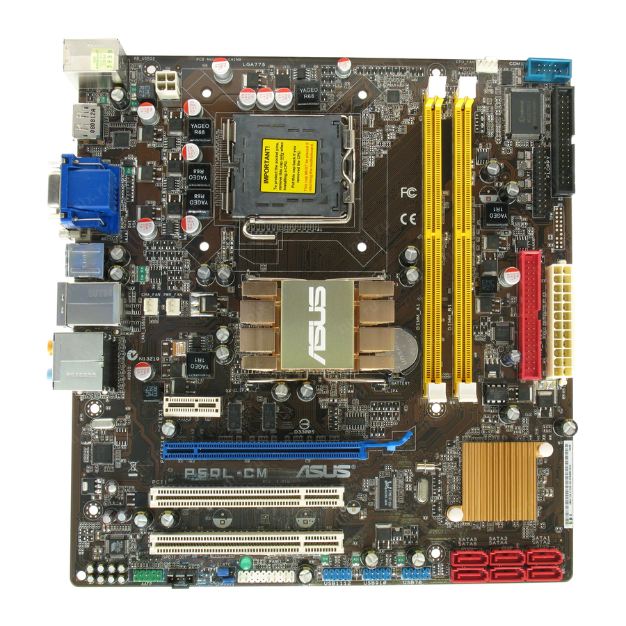
Page 16: Motherboard Layout
Floppy disk drive connector (34-1 pin FLOPPY) LPT connector (26-1 pin LPT) IDE connector (40-pin PRI-EIDE) Serial ATA connectors (7-pin SATA1-4) 22.9cm(9.0in) ATX12V LGA775 PWR_FAN Intel ® PCIEX16 P5QL-CM PCI1 PCI2 CLRTC CHASSIS USB1112 USB910 SB_PWR PANEL Page 1-23 1-24... -
Page 17: Central Processing Unit (Cpu)
Contact your retailer immediately if the PnP cap is missing, or if you see any damage to the PnP cap/socket contacts/motherboard components. ASUS will shoulder the cost of repair only if the damage is shipment/transit-related. • Keep the cap after installing the motherboard. ASUS will process Return Merchandise Authorization (RMA) requests only if the motherboard comes with the cap on the LGA775 socket. - Page 18 Press the load lever with your thumb (A), then move it to the left (B) until it is released from the retention tab. To prevent damage to the socket pins, do not remove the PnP cap unless you are installing a CPU. Lift the load lever in the direction of the arrow to a 135º...
- Page 19 To prevent contaminating the paste, DO NOT spread the paste with your finger directly. Close the load plate (A), then push the load lever (B) until it snaps into the retention tab. ASUS P5QL-CM...
-
Page 20: Installing The Cpu Heatsink And Fan
1.6.2 Installing the CPU heatsink and fan The Intel® LGA775 processor requires a specially designed heatsink and fan assembly to ensure optimum thermal condition and performance. • When you buy a boxed Intel heatsink assembly. If you buy a CPU separately, ensure that you use only Intel multi-directional heatsink and fan. -
Page 21: Uninstalling The Cpu Heatsink And Fan
Disconnect the CPU fan cable from the connector on the motherboard. Rotate each fastener counterclockwise. Pull up two fasteners at a time in a diagonal sequence to disengage the heatsink and fan assembly from the motherboard. ASUS P5QL-CM CPU_FAN 1-11... -
Page 22: System Memory
1.7.1 Overview The motherboard comes with four Double Data Rate 2 (DDR2) Dual Inline Memory Modules (DIMM) sockets. The figure illustrates the location of the DDR2 DIMM sockets: P5QL-CM P5QL-CM 240-pin DDR2 DIMM sockets 1-12 Channel Sockets Channel A DIMM_A... -
Page 23: Memory Configurations
Use a maximum of 3GB system memory if you are using a 32-bit Windows Install a 64-bit Windows the motherboard. • This motherboard does not support DIMMs made up of 256 megabits (Mb) or less. P5QL-CM Motherboard Qualified Vendors Lists (QVL) DDR2-667 MHz capability Vendor Part No. - Page 24 Vendor Part No. AL6E8E63J-6E1 AL7E8E63J-6E1 AL7E8F73C-6E1 Nanya NT512T64U88A1BY-3C Nanya NT1GT64U8HB0BY-3C GEIL GX21GB5300SX GEIL GX22GB5300LX GEIL GX24GB5300LDC G.SKILL F2-5400PHU2-2GBNT G.SKILL F2-5300CL5D-4GBMQ Super T667UB1GV Talent Twinmos 8D-A3JK5MPETP Samsung M378T5263AZ3-CE6 ELIXIR M2Y1G64TU8HA2B-3C ELIXIR M2Y1G64TU8HBOB-3C Leadmax LRMP512U64A8-Y5 DDRII 512 PC667 MDT 1024MB AENEON AET660UD00-30DB97X AENEON AET760UD00-30DB97X AENEON...
- Page 25 Transcend 503499-7280 Transcend TS128MLQ64V8J Transcend TS64MLQ64V8J512MB Transcend TS128MLQ64V8J ADATA M2OAD6G3H3160Q1E58 VDATA M2GVD6G3H3160Q1E52 ADATA M2OAD6G314170Q1E58 VDATA M2GVD6G314170Q1E58 ASUS P5QL-CM Size Chip No. Heat-Sink Package 512MB Heat-Sink Package 512MB V59C1512804QCF25SY032 406PECPA V59C1512804QCF25S0061 904PECJA 1G(Kit of 2) Heat-Sink Package 512MB E5108AJBG-8E-E E5108AJBG-8E-E E5108AJBG-8E-E...
- Page 26 Vendor Part No. AL7E8F73C-8E1 AL8E8F73C-8E1 GEIL GB22GB6400C4DC GEIL GB24GB6400C4QC GEIL GB22GB6400C5DC GEIL GB24GB6400C5QC GEIL GX22GB6400DC GEIL GE22GB800C4DC GEIL GE24GB800C4QC GEIL GX22GB6400UDC GEIL GE22GB800C5DC GEIL GE24GB800C5QC GEIL GB24GB6400C4DC GEIL GB24GB6400C5DC GEIL GB28GB6400C5QC GEIL GB28GB6400C4QC GEIL GX22GB6400LX GEIL GX24GB6400DC GEIL GE28GB800C5QC GEIL GE28GB800C4QC GEIL GX22GB6400CUSC...
- Page 27 B*: Supports one pair of modules inserted into either the yellow slot or the black slot or the black slots as one pair of Dual-channel memory configuration. Visit the ASUS website at www.asus.com for the latest QVL. ASUS P5QL-CM Size Chip No.
-
Page 28: Installing A Dimm
1.7.3 Installing a DIMM Unplug the power supply before adding or removing DIMMs or other system components. Failure to do so can cause severe damage to both the motherboard and the components. To install a DIMM: Press the retaining clips outward to unlock a DDR2 DIMM socket. -
Page 29: Expansion Slots
This motherboard supports PCI Express x1 network cards, SCSI cards, and other cards that comply with the PCI Express specifications. 1.8.5 PCI Express x16 slot This motherboard supports a PCI Express x16 graphics card that complies with the PCI Express specifications. ASUS P5QL-CM 1-19... -
Page 30: Clear Rtc Ram (Clrtc)
CMOS RTC RAM data. The onboard button cell battery powers the RAM data in CMOS, which include system setup information such as system passwords. P5QL-CM P5QL-CM Clear RTC RAM To erase the RTC RAM: 1. Turn OFF the computer and unplug the power cord. -
Page 31: Connectors
8-channel configuration, the function of this port becomes Front Speaker Out. Microphone port (pink). This port connects a microphone. Side Speaker Out port (gray). This port connects the side speakers in an 8-channel audio configuration. ASUS P5QL-CM SPEED LED Status Description 10 Mbps connection... - Page 32 Refer to the audio configuration table below for the function of the audio ports in 2, 4, 6 or 8-channel configuration. Audio 2, 4, 6, or 8-channel configuration Port Headset 2-channel Light Blue Line In Lime Line Out Pink Mic In Orange –...
-
Page 33: Internal Connectors
P5QL-CM P5QL-CM fan connectors Only the CPU fan supports the ASUS Q-FAN feature. Digital audio connector (4-1 pin SPDIF_OUT) This connector is for an additional Sony/Philips Digital Interface (S/PDIF) port. Connect the S/PDIF Out module cable to this connector, then install the module to a slot opening at the back of the system chassis. - Page 34 P5QL-CM P5QL-CM ATX power connectors • For a fully configured system, we recommend that you use a power supply unit (PSU) that complies with ATX 12 V Specification 2.0 (or later version) and provides a minimum power of 400 W.
- Page 35 FDD cable with a covered Pin 5. The Floppy Disk Drive cable is purchased separately. P5QL-CM P5QL-CM Floppy disk drive connector Chassis intrusion connector (4-1 pin CHASSIS) This connector is for a chassis-mounted intrusion detection sensor or switch. Connect one end of the chassis intrusion sensor or switch cable to this connector. The chassis intrusion sensor or switch sends a high-level signal to this connector when a chassis component is removed or replaced.
-
Page 36: Ide Connectors
The LPT (Line Printing Terminal) connector supports devices such as a printer. LPT standardizes as IEEE 1394, which is the parallel port interface on IBM PC-compatible computers. P5QL-CM P5QL-CM Parallel Port Connector 1-26 Drive jumper setting Mode of device(s) Cable-Select or Master... -
Page 37: System Panel Connector (20-8 Pin Panel)
System panel connector (20-8 pin PANEL) This connector supports several chassis-mounted functions. P5QL-CM P5QL-CM System panel connector • System power LED (2-pin PLED) This 2-pin connector is for the system power LED. Connect the chassis power LED cable to this connector. The system power LED lights up when you turn on the system power, and blinks when the system is in sleep mode. - Page 38 Never connect a 1394 cable to the USB connectors. Doing so will damage the motherboard! You can connect the front panel USB cable to the ASUS Q-Connector (USB, blue) first, and then install the Q-Connector (USB) to the USB connector onboard if your chassis supports front panel USB ports.
- Page 39 HD Audio or legacy AC`97 audio standard. Connect one end of the front panel audio I/O module cable to this connector. P5QL-CM P5QL-CM Analog front panel connector • We recommend that you connect a high-definition front panel audio module to this connector to avail of the motherboard’s high-definition audio capability.
-
Page 40: Software Support
1.11 Software support 1.11.1 Installing an operating system This motherboard supports Windows latest OS version and corresponding updates to maximize the features of your hardware. • Motherboard settings and hardware options vary. Use the setup procedures presented in this section for reference only. Refer to your OS documentation for detailed information. •... -
Page 41: Chapter 2 Bios Information
BIOS in the future. Copy the original motherboard BIOS using the ASUS Update or AFUDOS utilities. 2.1.1 ASUS Update utility The ASUS Update is a utility that allows you to manage, save, and update the motherboard BIOS in Windows environment. ®... -
Page 42: Asus Ez Flash 2 Utility
Follow the onscreen instructions to complete the updating process. 2.1.2 ASUS EZ Flash 2 utility The ASUS EZ Flash 2 feature allows you to update the BIOS without using a DOS-based utility. Before you start using this utility, download the latest BIOS file from the ASUS website at www.asus.com. -
Page 43: Asus Crashfree Bios 3 Utility
2.1.3 ASUS CrashFree BIOS 3 utility The ASUS CrashFree BIOS 3 is an auto recovery tool that allows you to restore the BIOS file when it fails or gets corrupted during the updating process. You can update a corrupted BIOS file using the motherboard support DVD or a USB flash disk that contains the updated BIOS file. -
Page 44: Bios Setup Program
Restart the system after the utility completes the updating process. • Only a USB flash disk with FAT 32/16 format and single partition can support ASUS CrashFree BIOS 3. The device size should be smaller than 8GB. • DO NOT shut down or reset the system while updating the BIOS! Doing so can cause system boot failure! The recovered BIOS may not be the latest BIOS version for this motherboard. -
Page 45: Bios Menu Screen
• The BIOS setup screens shown in this section are for reference purposes only, and may not exactly match what you see on your screen. • Visit the ASUS website at www.asus.com to download the latest BIOS file for this motherboard. -
Page 46: Navigation Keys
2.2.3 Navigation keys At the bottom right corner of a menu screen are the navigation keys for that particular menu. Use the navigation keys to select items in the menu and change the settings. Some of the navigation keys differ from one screen to another. 2.2.4 Menu items The highlighted item on the menu bar displays the specific items for that menu. -
Page 47: Sata 1-6
SATA device type. Select [CDROM] if you are specifically configuring a CD-ROM drive. Select [ARMD] (ATAPI Removable Media Device) if your device is either a ZIP, LS-120, or MO drive. Configuration options: [Not Installed] [Auto] [CDROM] [ARMD] ASUS P5QL-CM BIOS SETUP UTILITY Boot... -
Page 48: Storage Configuration
LBA/Large Mode [Auto] Enables or disables the LBA mode. Setting to [Auto] enables the LBA mode if the device supports this mode, and if the device was not previously formatted with LBA mode disabled. Configuration options: [Disabled] [Auto] Block (Multi-sector Transfer) M [Auto] Enables or disables data multi-sectors transfers. -
Page 49: System Information
Select either one of the preset overclocking configuration options: Manual - allows you to individually set overclocking parameters. Auto - loads the optimal settings for the system. Overclock Profile - loads overclocking profiles with optimal parameters for stability when overclocking. ASUS P5QL-CM BIOS SETUP UTILITY Boot Tools Exit Adjust System frequency/voltage. -
Page 50: Dram Frequency [Auto]
The following item appears only when you set the AI Overclocking item to [Manual]. CPU Frequency [xxx] Displays the frequency sent by the clock generator to the system bus and PCI bus. The value of this item is auto-detected by the BIOS. Use the <+> and <-> keys to adjust the CPU frequency. -
Page 51: Cpu Configuration
Configuration options: [Disabled] [Enabled] Execute-Disable Bit Capability [Enabled] Allows you to enable or disable the No-Execution Page Protection Technology. Setting this item to [Disabled] forces the XD feature flag to always return to zero (0). Configuration options: [Disabled] [Enabled] ASUS P5QL-CM ® 2-11... -
Page 52: Chipset
The following item appears only when you installed an Intel Enhanced Intel Intel(R) SpeedStep(TM) Tech [Enabled] Allows you to use the Enhanced Intel [Enabled], you can adjust the system power settings in the operating system to use the EIST feature. Set this item to [Disabled] if you do not want to use the EIST. Configuration options: [Enabled] [Disabled] 2.4.3 Chipset... -
Page 53: Onboard Devices Configuration
Appears only when the Parallel Port Mode is set to [ECP]. This item allows you to set the Parallel Port ECP DMA. Configuration options: [DMA0] [DMA1] [DMA3] Parallel Port IRQ [IRQ7] Allows you to select parallel port IRQ. Configuration options: [IRQ5] [IRQ7] ASUS P5QL-CM PAVP Lite PAVP Paranoid 2-13... -
Page 54: Usb Configuration
2.4.5 USB Configuration The items in this menu allows you to change the USB-related features. Select an item then press <Enter> to display the configuration options. The Module Version and USB Devices Enabled items show the auto-detected values. If no USB device is detected, the item shows None. -
Page 55: Power Menu
[Power On], the system goes on after an AC power loss. When set to [Last State], the system goes into either off or on state, whatever the system state was before the AC power loss. Configuration options: [Power Off] [Power On] [Last State] ASUS P5QL-CM BIOS SETUP UTILITY Boot... -
Page 56: Hardware Monitor
Power On By PS/2 KB/Mouse [Disabled] When set to [Enabled], this parameter allows you to use the PS/2 KB/mouse to turn on the system. This feature requires an ATX power supply that provides at least 1A on the +5VSB lead. Configuration options: [Disabled] [Enabled] Resume On Ring [Disabled] Allows you to enable or disable RI to generate a wake event. -
Page 57: Boot Menu
This allows you to enable or disable the full screen logo display feature. Configuration options: [Disabled] [Enabled] Set this item to [Enabled] to use the ASUS MyLogo2 AddOn ROM Display Mode [Force BIOS] Sets the display mode for option ROM. Configuration options: [Force BIOS]... -
Page 58: Security
2.6.3 Security The Security menu items allow you to change the system security settings. Select an item then press <Enter> to display the configuration options. Change Supervisor Password Select this item to set or change the supervisor password. The Supervisor Password item on top of the screen shows the default Not Installed. -
Page 59: Tools Menu
2.7.1 ASUS EZ Flash 2 Allows you to run ASUS EZ Flash 2. When you press <Enter>, a confirmation message appears. Use the left/right arrow key to select between [Yes] or [No], then press <Enter> to confirm your choice. Please see section 2.1.3 for details. -
Page 60: Ai Net 2
2.7.3 AI NET 2 Check Realtek LAN cable [Disabled] Enables or disables checking of the Realtek LAN cable during the Power-On Self-Test (POST). Configuration options: [Disabled] [Enabled] Exit menu The Exit menu items allow you to load the optimal or failsafe default values for the BIOS items, and save or discard your changes to the BIOS items.
Need help?
Do you have a question about the P5QL-CM and is the answer not in the manual?
Questions and answers