Table of Contents
Advertisement
Advertisement
Table of Contents

Related Manuals for Asus P5QL-E - Motherboard - ATX


Summary of Contents for Asus P5QL-E - Motherboard - ATX
- Page 1 P5QL-E...
- Page 2 Product warranty or service will not be extended if: (1) the product is repaired, modified or altered, unless such repair, modification of alteration is authorized in writing by ASUS; or (2) the serial number of the product is defaced or missing.
-
Page 3: Table Of Contents
Special features ................1-2 1.3.1 Product highlights ............1-2 1.3.2 ASUS unique features ............ 1-4 1.3.3 ASUS Exclusive Overclocking Features ......1-6 Chapter 2: Hardware information Before you proceed ..............2-1 Motherboard overview ..............2-2 2.2.1 Placement direction ............2-2 Screw holes .............. - Page 4 4.1.1 ASUS Update utility ............4-1 4.1.2 Creating a bootable floppy disk ........4-4 4.1.3 ASUS EZ Flash 2 utility ........... 4-5 4.1.4 AFUDOS utility ..............4-6 4.1.5 ASUS CrashFree BIOS 3 utility ........4-8 BIOS setup program ..............4-9 4.2.1...
- Page 5 Contents 4.3.7 AHCI Configuration ............4-15 4.3.8 System Information ............4-16 Ai Tweaker menu ................ 4-16 4.4.1 Ai Overclock Tuner ............4-17 4.4.2 FSB Strap to North Bridge ..........4-18 4.4.3 DRAM Frequency ............4-18 4.4.4 DRAM Timing Control ........... 4-18 4.4.5 DRAM Static Read Control ..........
- Page 6 Boot Device Priority ............4-34 4.7.2 Boot Settings Configuration .......... 4-35 4.7.3 Security ................. 4-36 Tools menu ................. 4-38 4.8.1 ASUS EZ Flash 2 ............4-38 4.8.2 Express Gate ..............4-38 4.8.3 AI Net 2 ................. 4-39 4.8.4 ASUS O.C. Profile ............4-40 Exit menu ..................
- Page 7 Contents 5.4.1 RAID definitions ............5-46 5.4.2 Installing Serial ATA hard disks ........5-47 5.4.3 Intel RAID configurations ..........5-47 ® Creating a RAID driver disk ............5-55 5.5.1 Creating a RAID driver disk without entering the OS ..5-55 5.5.2 Creating a RAID/SATA driver disk in Windows ....
-
Page 8: Notices
Notices Federal Communications Commission Statement This device complies with Part 15 of the FCC Rules. Operation is subject to the following two conditions: • This device may not cause harmful interference, and • This device must accept any interference received including interference that may cause undesired operation. -
Page 9: Safety Information
Safety information Electrical safety • To prevent electrical shock hazard, disconnect the power cable from the electrical outlet before relocating the system. • When adding or removing devices to or from the system, ensure that the power cables for the devices are unplugged before the signal cables are connected. If possible, disconnect all power cables from the existing system before you add a device. -
Page 10: About This Guide
Refer to the following sources for additional information and for product and software updates. ASUS websites The ASUS website provides updated information on ASUS hardware and software products. Refer to the ASUS contact information. Optional documentation Your product package may include optional documentation, such as warranty flyers, that may have been added by your dealer. -
Page 11: Conventions Used In This Guide
Conventions used in this guide To make sure that you perform certain tasks properly, take note of the following symbols used throughout this manual. DANGER/WARNING: Information to prevent injury to yourself when trying to complete a task. CAUTION: Information to prevent damage to the components when trying to complete a task. -
Page 12: P5Ql-E Specifications Summary
DDR2 1066 / 800 / 667 MHz memory modules - Supports up to 16 GB system memory * Refer to www.asus.com or this user manual for the Memory QVL (Qualified Vendors Lists). Expansion Slots 1 x PCIe x16 slot... - Page 13 P5QL-E specifications summary ASUS Unique Features ASUS Power Saving Solution: - ASUS EPU - Six Engine - ASUS 3rd Generation 8-phase Power Design - ASUS AI Nap ASUS Unique Feature - ASUS Express Gate ASUS Quiet Thermal Solution: - ASUS Fanless Design: unique stylish heatsink...
- Page 14 1 x System panel (Q-connector) BIOS Features 8 Mb Flash ROM, AMI BIOS, PnP, DMI2.0, WfM2.0, SM BIOS 2.4, ACPI 3.0, ASUS EZ Flash 2, ASUS CrashFree BIOS 3 Manageability WOL by PME, WOR by PME, WOR by Ring, PXE...
-
Page 15: Chapter 1: Product Introduction
This chapter describes the motherboard features and the new technologies it supports. Chapter 1: Product introduction... - Page 16 Chapter summary Welcome! ..................1-1 Package contents ................. 1-1 Special features ................1-2 ASUS P5QL-E...
-
Page 17: Welcome
® The motherboard delivers a host of new features and latest technologies, making it another standout in the long line of ASUS quality motherboards! Before you start installing the motherboard, and hardware devices on it, check the items in your package with the list below. -
Page 18: Special Features
Special features 1.3.1 Product highlights Intel Core™2 Extreme / Core™ 2 Quad / ® Core™2 Duo Processor Support This motherboard supports the latest Intel Core™ 2 Extreme / Core™ 2 Quad / ® Core™ 2 Duo processors in the LGA775 package. It is excellent for multi-tasking, multi-media and enthusiastic gamers with 1600 / 1333 / 1066 / 800 MHz FSB. -
Page 19: High Definition Audio
Green ASUS This motherboard and its packaging comply with the European Union’s Restriction on the use of Hazardous Substances (RoHS). This is in line with the ASUS vision of creating environment-friendly and recyclable products/packagings to safeguard consumers’ health while minimizing the impact on the environment. -
Page 20: Asus Unique Features
CMOS or a separate file, giving users freedom to share and distribute their favorite settings. ASUS CrashFree BIOS 3 The ASUS CrashFree BIOS 3 allows users to restore corrupted BIOS data from a USB flash disk containing the BIOS file. Chapter 1: Product Introduction... - Page 21 BIOS easily without preparing a bootable diskette or using an OS-based flash utility. ASUS Q-Shield The specially designed ASUS Q-Shield does without the usual “figners” - making it convenient and easy to install. With better electric conductivity, it really protects your motherboard against static electricity and shields it against Electronic Magnetic Interference (EMI).
-
Page 22: Asus Exclusive Overclocking Features
1.3.3 ASUS Exclusive Overclocking Features AI Booster The ASUS AI Booster allows you to overclock the CPU speed in Windows environment without the hassle of booting the BIOS. Precision Tweaker 2 Allows the user to adjust the NB Voltage, FSB termination Voltage, CPU PLL Voltage and the DRAM Voltage in 0.02v steps to finetune voltages to achieve the... -
Page 23: Chapter 2: Hardware Information
This chapter lists the hardware setup procedures that you have to perform when installing system components. It includes description of the jumpers and connectors on the motherboard. Chapter 2: Hardware information... - Page 24 Chapter summary Before you proceed ..............2-1 Motherboard overview ..............2-2 Central Processing Unit (CPU) ........... 2-5 System memory ................. 2-11 Expansion slots ................2-17 Jumpers ..................2-20 Connectors ................. 2-22 ASUS P5QL-E...
-
Page 25: Before You Proceed
The illustration below shows the location of the onboard LED. SB_PWR P5QL-E Standy Power Powered Off P5QL-E Onboard LED ASUS P5QL-E... -
Page 26: Motherboard Overview
Motherboard overview Before you install the motherboard, study the configuration of your chassis to ensure that the motherboard fits into it. Make sure to unplug the power cord before installing or removing the motherboard. Failure to do so can cause you physical injury and damage motherboard components. -
Page 27: Motherboard Layout
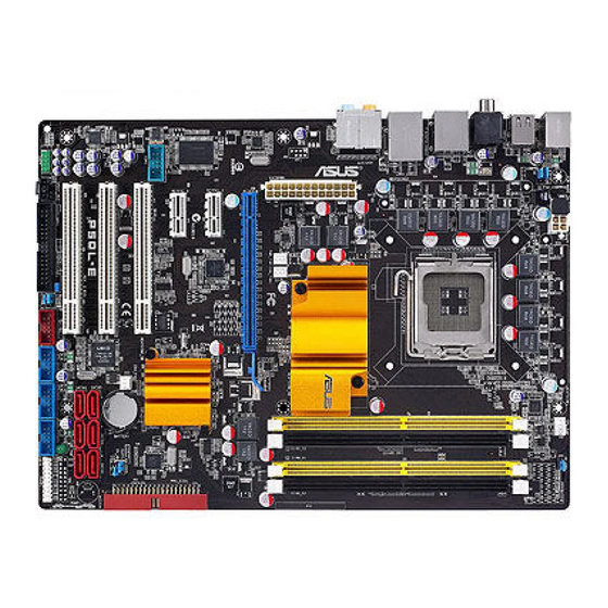
CMOS Power PCI2 SATA4 SATA2 SATA5 L-FW3227 P5QL-E ALC1200 USBPW7-10 PCI3 SATA6 SATA3 SATA1 USBPW1112 SB_PWR SPDIF_OUT IE1394_2 USB1112 USB910 USB78 CHASSIS FLOPPY PANEL AAFP Refer to 2.7 Connectors for more information about rear panel connectors and internal connectors. ASUS P5QL-E... -
Page 28: Layout Contents
CHA_FAN1-2, 3-pin PWR_FAN) Optical drive audio connector (4-pin CD) 2-29 Chassis intrusion connector (4-1 pin CHASSIS) 2-30 Digital audio connector (4-1 pin SPDIF_OUT for ASUS HDMI 2-30 VGA card) Front panel audio connector (10-1 pin AAFP) 2-31 Serial port connector (10-1 pin COM1) -
Page 29: Central Processing Unit (Cpu)
ASUS will shoulder the cost of repair only if the damage is shipment/transit-related. • Keep the cap after installing the motherboard. ASUS will process Return Merchandise Authorization (RMA) requests only if the motherboard comes with the cap on the LGA775 socket. -
Page 30: Installing The Cpu
2.3.1 Installing the CPU To install a CPU: Locate the CPU socket on the motherboard. P5QL-E P5QL-E CPU socket 775 Before installing the CPU, make sure that the cam box is facing towards you and the load lever is on your left. Press the load lever with your thumb Retention tab (A), then move it to the left (B) until... - Page 31 The Thermal Interface Material is toxic and inedible. If it gets into your eyes or touches your skin, ensure to wash it off immediately, and seek professional medical help. To prevent contaminating the paste, DO NOT spread the paste with your finger directly. ASUS P5QL-E...
- Page 32 Close the load plate (A), then push the load lever (B) until it snaps into the retention tab. The motherboard supports Intel ® LGA775 processors with the Intel ® Enhanced Memory 64 Technology (EM64T), Enhanced Intel SpeedStep Technology ® (EIST), and Hyper-Threading Technology. Refer to the Appendix for more information on these CPU features.
-
Page 33: Installing The Cpu Heatsink And Fan
Push down two fasteners at a time in a diagonal sequence to secure the heatsink and fan assembly in place. Orient the heatsink and fan assembly such that the CPU fan cable is closest to the CPU fan connector. ASUS P5QL-E... -
Page 34: Uninstalling The Cpu Heatsink And Fan
Connect the CPU fan cable to the connector on the motherboard labeled CPU_FAN. CPU_FAN P5QL-E P5QL-E CPU fan connector DO NOT forget to connect the CPU fan connector! Hardware monitoring errors can occur if you fail to plug this connector. 2.3.3 Uninstalling the CPU heatsink and fan To uninstall the CPU heatsink and fan:... -
Page 35: System Memory
The motherboard comes with four Double Data Rate 2 (DDR2) Dual Inline Memory Modules (DIMM) sockets. The figure illustrates the location of the DDR2 DIMM sockets: P5QL-E P5QL-E 240-pin DDR2 DIMM Sockets Channel Sockets Channel A DIMM_A1 and DIMM_A2 Channel B DIMM_B1 and DIMM_B2 ASUS P5QL-E 2-11... -
Page 36: Memory Configurations
2.4.2 Memory configurations You may install 256 MB, 512 MB, 1 GB, 2 GB, and 4GB unbuffered non-ECC DDR2 DIMMs into the DIMM sockets. Recommended Memory Configurations Sockets Mode DIMM_A1 DIMM_A2 DIMM_B1 DIMM_B2 Populated – – – Single-Channel – – Populated –... - Page 37 M2GVD6G314170Q1E58 VDATA VD29608A8A-25EG80813 • • • AL7E8F73C-8E1 A3R1GE3CFF734MAA0E • • • AL8E8F73C-8E1 A3R1GE3CFF734MAA0E • • • GEIL GB22GB6400C4DC GEIL GL2L64M088BA30EB • • • GEIL GB22GB6400C5DC GEIL GL2L64M088BA30EB • • GEIL GX22GB6400DC GEIL Heat-Sink Package • • • ASUS P5QL-E 2-13...
- Page 38 DDR2-800 MHz capability DIMM support Size Vendor Part No. Chip Brand Chip No. GEIL GE22GB800C4DC GEIL Heat-Sink Package • • • GEIL GE24GB800C4QC GEIL Heat-Sink Package • • • GEIL GX22GB6400UDC GEIL Heat-Sink Package • • • GEIL GE22GB800C5DC GEIL Heat-Sink Package •...
- Page 39 Supports one pair of modules inserted into either Channel A or Channel B as one pair of Dual-channel memory configuration. Supports four modules inserted into the yellow and black slots as two pairs of Dual-channel memory configuration. Visit the ASUS website for the latest DDR2 QVL. ASUS P5QL-E 2-15...
-
Page 40: Installing A Ddr2 Dimm
2.4.3 Installing a DDR2 DIMM Make sure to unplug the power supply before adding or removing DIMMs or other system components. Failure to do so may cause severe damage to both the motherboard and the components. Unlock a DDR2 DIMM socket DDR2 DIMM notch by pressing the retaining clips outward. -
Page 41: Expansion Slots
IRQ” or that the cards do not need IRQ assignments. Otherwise, conflicts will arise between the two PCI groups, making the system unstable and the card inoperable. Refer to the table on the next page for details. ASUS P5QL-E 2-17... -
Page 42: Interrupt Assignments
2.5.3 Interrupt assignments Standard interrupt assignments Priority Standard function System Timer Keyboard Controller – Redirect to IRQ#9 IRQ Holder for PCI Steering* Communications Port (COM1)* IRQ Holder for PCI Steering* Floppy disk controller Reserve System CMOS/Real Time Clock IRQ Holder for PCI Steering* IRQ Holder for PCI Steering* IRQ Holder for PCI Steering* PS/2 compatible mouse port*... -
Page 43: Pci Slots
16 2.0 graphic cards complying with the PCI Express specifications. Refer to the figure below for the location of the slot. PCI Express 2.0 x16 slot PCI Express x1 slot 1 PCI Express x1 slot 2 PCI slot 3 PCI slot 1 PCI slot 2 ASUS P5QL-E 2-19... -
Page 44: Jumpers
Jumpers Clear RTC RAM (3-pin CLRTC) This jumper allows you to clear the Real Time Clock (RTC) RAM in CMOS. You can clear the CMOS memory of date, time, and system setup parameters by erasing the CMOS RTC RAM data. The onboard button cell battery powers the RAM data in CMOS, which include system setup information such as system passwords. - Page 45 For system failure due to the wrong setting of the OV_CPU jumper, shut down the computer and move the cap back to pins 2-3. • The system may need a better cooling system (for example, a water-cooling system) to work stably under high voltage settings. ASUS P5QL-E 2-21...
- Page 46 USB device wake-up (3-pin USBPW1-4, PS2_USBPW56, USBPW7-10, USBPW1112) Set these jumpers to +5V to wake up the computer from S1 sleep mode (CPU stopped, DRAM refreshed, system running in low power mode) using the connected USB devices. Set to +5VSB to wake up from S3 and S4 sleep modes.
-
Page 47: Connectors
Rear Speaker Out port (black). This port connects the rear speakers on a 4-channel, 6-channel, or 8-channel audio configuration. Line In port (light blue). This port connects the tape, CD, DVD player, or other audio sources. 2-23 ASUS P5QL-E... - Page 48 Line Out port (lime). This port connects a headphone or a speaker. In 4-channel, 6-channel, and 8-channel configuration, the function of this port becomes Front Speaker Out. 10. Microphone port (pink). This port connects a microphone. 11. Side Speaker Out port (gray). This port connects the side speakers in an 8-channel audio configuration.
-
Page 49: Internal Connectors
Pin 5 on the connector is removed to prevent incorrect cable connection when using a FDD cable with a covered Pin 5. FLOPPY PIN1 P5QL-E NOTE:Orient the red markings on the floppy ribbon cable to PIN 1. P5QL-E Floppy disk drive connector 2-25 ASUS P5QL-E... - Page 50 IDE connector (40-1 pin PRI_EIDE) The onboard IDE connector is for the Ultra DMA 133/100/66 signal cable. There are three connectors on each Ultra DMA 133/100/66 signal cable: blue, black, and gray. Connect the blue connector to the motherboard’s IDE connector, then select one of the following modes to configure your device.
-
Page 51: Ich10R Serial Ata Connectors (7-Pin Sata)
SATA device. Or you may connect the right-angle side of SATA cable to the onboard SATA port to avoid mechanical conflict with huge graphics cards. When using hot-plug and NCQ, set the configure SATA as in the BIOS to [AHCI]. 2-27 ASUS P5QL-E... - Page 52 If your chassis suppots front panel USB ports, you can attach a front panel USB cable to these connectors. Connect the USB cable to ASUS Q-Connector (USB, blue) first, and then install the Q-Connector (USB) to the USB connector onboard.
- Page 53 You can attach a FireWire/1394 cable to this connector if your chassis suppots the front panel IEEE1394 port. Connect the 1394 cable to ASUS Q-Connector (1394, red) first, and then install the Q-Connector (1394) to the 1394 connector onboard.
-
Page 54: Cpu, Chassis, And Power Fan Connectors (4-Pin Cpu_Fan, 3-Pin)
These are not jumpers! DO NOT place jumper caps on the fan connectors! Only the CPU_FAN and CHA_FAN1-2 connectors support the ASUS Fan Xpert feature. Optical drive audio connector (4-pin CD) This connector allows you to receive stereo audio input from sound sources such as a CD-ROM, TV tuner, or MPEG card. - Page 55 Digital audio connector (4-1 pin SPDIF_OUT for ASUS HDMI VGA card) This connector is for an additional Sony/Philips Digital Interface (S/PDIF) port(s). If you are using an ASUS HDMI-equipped graphics card, connect the HDMI card to this connector with a S/PDIF Out cable.
-
Page 56: Front Panel Audio Connector (10-1 Pin Aafp)
10. Front panel audio connector (10-1 pin AAFP) This connector is for a chassis-mounted front panel audio I/O module that supports either HD Audio or legacy AC`97 audio standard. Connect one end of the front panel audio I/O module cable to this connector. AAFP PIN 1 PIN 1... -
Page 57: Atx Power Connectors (24-Pin Eatxpwr, 8-Pin Eatx12V)
• If you are uncertain about the minimum power supply requirement for your system, refer to the Recommended Power Supply Wattage Calculator at http://support.asus.com/PowerSupplyCalculator/PSCalculator. aspx?SLanguage=en-us for details. 2-33 ASUS P5QL-E... -
Page 58: System Panel Connector 20-8 Pin Panel
13. System panel connector (20-8 pin PANEL) This connector supports several chassis-mounted functions. PLED SPEAKER PANEL PIN 1 IDE_LED PWRSW RESET P5QL-E * Requires an ATX power supply P5QL-E System panel connector • System power LED (2-pin PLED) This 2-pin connector is for the system power LED. Connect the chassis power LED cable to this connector. -
Page 59: Asus Q-Connector (System Panel)
ASUS Q-Connector (system panel) You can use the ASUS Q-Connector to connect/disconnect chassis front panel cables in a few steps. Refer to the instructions below to install the ASUS Q- Connector. Connect the front panel cables to the ASUS Q-Connector. -
Page 60: Chapter 3: Powering Up
This chapter describes the power up sequence, the vocal POST messages, and ways of shutting down the system. Powering up... - Page 61 Chapter summary Starting up for the first time ............3-1 Turning off the computer ............. 3-2 ASUS P5QL-E...
-
Page 62: Starting Up For The First Time
One continuous beep followed by three No VGA detected short beeps One continuous beep followed by four Hardware component failure short beeps At power on, hold down the <Delete> key to enter the BIOS Setup. Follow the instructions in Chapter 4. ASUS P5QL-E... -
Page 63: Turning Off The Computer
Turning off the computer 3.2.1 Using the OS shut down function If you are using Windows ® Click the Start button then select Turn Off Computer. Click the Turn Off button to shut down the computer. The power supply should turn off after Windows ®... -
Page 64: Chapter 4: Bios Setup
This chapter tells how to change the system settings through the BIOS Setup menus. Detailed descriptions of the BIOS parameters are also provided. Chapter 3: BIOS setup... - Page 65 Managing and updating your BIOS ..........4-1 BIOS setup program ..............4-9 Main menu .................. 4-12 Ai Tweaker menu ................ 4-16 Advanced menu ................. 4-24 Power menu ................4-30 Boot menu .................. 4-34 Tools menu ................. 4-38 Exit menu ..................4-41 ASUS P5QL-E...
-
Page 66: Managing And Updating Your Bios
® ASUS EZ Flash 2 (Updates the BIOS using a floppy disk or USB flash disk.) AFUDOS (Updates the BIOS using a bootable floppy disk) ASUS CrashFree BIOS 3 (Updates the BIOS using a USB flash disk or the motherboard support DVD when the BIOS file fails or gets corrupted.) - Page 67 To update the BIOS through the Internet: desktop by clicking Start Launch the ASUS Update utility from the Windows ® > Programs > ASUS > ASUSUpdate > ASUSUpdate. The ASUS Update main window appears. Select Update BIOS from the Select the ASUS FTP site nearest...
- Page 68 To update the BIOS through a BIOS file: desktop by clicking Start Launch the ASUS Update utility from the Windows ® > Programs > ASUS > ASUSUpdate > ASUSUpdate. The ASUS Update main window appears. Select Update BIOS from a file option from the drop-down menu, then click Next.
-
Page 69: Creating A Bootable Floppy Disk
4.1.2 Creating a bootable floppy disk Do either one of the following to create a bootable floppy disk. DOS environment a. Insert a 1.44MB floppy disk into the drive. b. At the DOS prompt, type format A:/S then press <Enter>. Windows XP environment ®... -
Page 70: Asus Ez Flash 2 Utility
4.1.3 ASUS EZ Flash 2 utility The ASUS EZ Flash 2 feature allows you to update the BIOS without having to go through the long process of booting from a floppy disk and using a DOS-based utility. The EZ Flash 2 utility is built-in the BIOS chip so it is accessible by pressing <Alt>... -
Page 71: Afudos Utility
Updating the BIOS file To update the BIOS file using the AFUDOS utility: Visit the ASUS website (www.asus.com) and download the latest BIOS file for the motherboard. Save the BIOS file to a bootable floppy disk. Chapter 4: BIOS setup... - Page 72 A:\>afudos /iP5QLE.ROM The utility verifies the file and starts updating the BIOS. A:\>afudos /iP5QLE.ROM AMI Firmware Update Utility - Version 1.19(ASUS V2.07(03.11.24BB)) Copyright (C) 2002 American Megatrends, Inc. All rights reserved. WARNING!! Do not turn off power during flash BIOS Reading file ..done Reading flash ..
-
Page 73: Asus Crashfree Bios 3 Utility
4.1.5 ASUS CrashFree BIOS 3 utility The ASUS CrashFree BIOS 3 is an auto recovery tool that allows you to restore the BIOS file when it fails or gets corrupted during the updating process. You can update a corrupted BIOS file using the motherboard support DVD or the USB flash disk that contains the updated BIOS file. -
Page 74: Bios Setup Program
The BIOS setup screens shown in this section are for reference purposes only, and may not exactly match what you see on your screen. • Visit the ASUS website (www.asus.com) to download the latest BIOS file for this motherboard. ASUS P5QL-E... -
Page 75: Bios Menu Screen
4.2.1 BIOS menu screen Menu items Menu bar Configuration fields General help BIOS SETUP UTILITY Main Ai Tweaker Advanced Power Boot Tools Exit Use [ENTER], [TAB] System Time [10:55:25] or [SHIFT-TAB] to System Date [Mon 04/07/2008] select a field. Legacy Diskette A [1.44M, 3.5 in.] Language [English]... -
Page 76: Menu Items
Up/Down arrow keys or <Page Up> /<Page Down> keys to display the other items on the screen. 4.2.9 General help Pop-up window At the top right corner of the menu screen Scroll bar is a brief description of the selected item. ASUS P5QL-E 4-11... -
Page 77: Main Menu
Main menu When you enter the BIOS Setup program, the Main menu screen appears, giving you an overview of the basic system information. Refer to section 3.2.1 BIOS menu screen for information on the menu screen items and how to navigate through them. BIOS SETUP UTILITY Main Ai Tweaker... -
Page 78: Sata 1-6
When set to [Disabled], the data transfer from and to the device occurs one sector at a time. Configuration options: [Disabled] [Auto] PIO Mode [Auto] Allows you to select the data transfer mode. Configuration options: [Auto] [0] [1] [2] [3] [4] ASUS P5QL-E 4-13... -
Page 79: Storage Configuration
DMA Mode [Auto] Selects the DMA mode. Configuration options: [Auto] [SWDMA0] [SWDMA1] [SWDMA2] [MWDMA0] [MWDMA1] [MWDMA2] [UDMA0] [UDMA1] [UDMA2] [UDMA3] [UDMA4] [UDMA5] SMART Monitoring [Auto] Sets the Smart Monitoring, Analysis, and Reporting Technology. Configuration options: [Auto] [Disabled] [Enabled] 32Bit Data Transfer [Enabled] Enables or disables 32-bit data transfer. -
Page 80: Ahci Configuration
SATA Port1 [Auto] Allows you to select the type of device connected to the system. Configuration options: [Auto] [Not Installed] SMART Monitoring [Enabled] Allows you to set the Self-Monitoring, Analysis and Reporting Technology. Configration options: [Disabled] [Enabled] ASUS P5QL-E 4-15... -
Page 81: System Information
4.3.8 System Information This menu gives you an overview of the general system specifications. The BIOS automatically detects the items in this menu. BIOS SETUP UTILITY Main AMIBIOS Version : 0404 Build Date: 06/16/08 Processor Type : Intel(R) Core(TM)2 CPU 6300@ 1.86GHz Speed : 1866MHz Count... -
Page 82: Ai Overclock Tuner
FSB frequency. You can also type the desired CPU frequency using the numeric keypad. The values range from 200 to 800. Refer to the table below for the correct Front Side Bus and CPU External Frequency settings. ASUS P5QL-E 4-17... -
Page 83: Fsb Strap To North Bridge
FSB/CPU External Frequency Synchronization Front Side Bus CPU External Frequency FSB 1600 400 MHz FSB 1333 333 MHz FSB 1066 266 MHz FSB 800 200 MHz The following item appears only when you set the Ai Overclock Tuner item to [Manual] and [X.M.P.]. - Page 84 Configuration options: [Auto] [1 DRAM Clocks] – [15 DRAM Clocks] WRITE to READ Delay(D) [Auto] Configuration options: [Auto] [1 DRAM Clocks] – [15 DRAM Clocks] READ To READ Delay(S) [Auto] Configuration options: [Auto] [1 DRAM Clocks] – [15 DRAM Clocks] ASUS P5QL-E 4-19...
-
Page 85: Dram Static Read Control
READ To READ Delay(D) [Auto] Configuration options: [Auto] [1 DRAM Clocks] – [15 DRAM Clocks] WRITE To WRITE Delay(S) [Auto] Configuration options: [Auto] [1 DRAM Clocks] – [15 DRAM Clocks] WRITE To WRITE Delay(D) [Auto] Configuration options: [Auto] [1 DRAM Clocks] – [15 DRAM Clocks] 3rd Information: 13-5-1-5-5 The values vary depending on your settings of the following sub-items: WRITE to PRE Delay [Auto]... -
Page 86: Cpu Spread Spectrum
[1.70000V]. See 2. CPU / Northbridge overvoltage setting on page 2-19 for details. 4.4.13 CPU PLL Voltage [Auto] Allows you to set the CPU PLL voltage. The values range from 1.50V to 2.78V with a 0.02V interval. ASUS P5QL-E 4-21... -
Page 87: Fsb Termination Voltage
4.4.14 FSB Termination Voltage [Auto] Allows you to set the front side bus termination voltage. The values range from 1.20V* to 1.90V with a 0.02V interval. The minimum value of this item becomes 1.10V when a 45nm CPU is installed. 4.4.15 Memory Voltage [Auto] Allows you to set the DRAM voltage. -
Page 88: Pcie Sata Voltage
Allows you to enable or set CPU GTL Reference. Set a very high voltage may damage the component permanently, set a very low voltage may cause the system to become unstable. Configuration options: [Auto] [0.667V] [0.65V] [0.63V] [0.615V] ASUS P5QL-E 4-23... -
Page 89: Advanced Menu
Advanced menu The Advanced menu items allow you to change the settings for the CPU and other system devices. Take caution when changing the settings of the Advanced menu items. Incorrect field values can cause the system to malfunction. BIOS SETUP UTILITY Main Ai Tweaker Advanced... - Page 90 The following item appears only when you set the CPU Ratio control item to [Auto]. Intel(R) SpeedStep (TM) Tech [Enabled] When set to [Disable], the CPU runs at its default speed. When set to [Enabled], the CPU speed is controlled by the operating system. Configuration options: [Disabled] [Enabled] ASUS P5QL-E 4-25...
-
Page 91: Chipset
4.5.2 Chipset The Chipset menu allows you to change the advanced chipset settings. Select an item then press <Enter> to display the sub-menu. BIOS SETUP UTILITY Advanced Advanced Chipset Settings Configure North Bridge features. WARMING: Setting wrong values in below sections may cause system to malfunction. -
Page 92: Onboard Devices Configuration
Onboard PCIEX GbE LAN. Configuration options: [Enabled] [Disabled] LAN Option ROM [Disabled] Onboard PCIEX GbE LAN Boot ROM configuration. Configuration options: [Enabled] [Disabled Serial Port1 Address [3F8/IRQ4] Allows you to select the Serial Port1 base address. Configuration options: [Disabled] [3F8/IRQ4] [2F8/IRQ3] [3E8/IRQ4] [2E8/IRQ3] ASUS P5QL-E 4-27... -
Page 93: Usb Configuration
4.5.4 USB Configuration The items in this menu allows you to change the USB-related features. Select an item then press <Enter> to display the configuration options. BIOS SETUP UTILITY Advanced USB Configuration Options USB Devices Enabled: 1 Drive Disabled Enabled USB Functions [Enabled] USB 2.0 Controller... -
Page 94: Pcipnp
When set to [No], BIOS configures all the devices in the system. When set to [Yes] and if you install a Plug and Play operating system, the operating system configures the Plug and Play devices not required for boot. Configuration options: [No] [Yes] ASUS P5QL-E 4-29... -
Page 95: Power Menu
Power menu The Power menu items allow you to change the settings for the Advanced Power Management (APM). Select an item then press <Enter> to display the configuration options. BIOS SETUP UTILITY Main Ai Tweaker Advanced Power Boot Tools Exit Select the ACPI state Suspend Mode [Auto]... -
Page 96: Apm Configuration
Allows you to enable or disable the PME to wake up from S5 by PCI devices. Configuration options: [Disabled] [Enabled] Power On By PCIE Devices [Disabled] Allows you to enable or disable the PCIE devices to generate a wake event. Configuration options: [Disabled] [Enabled] ASUS P5QL-E 4-31... -
Page 97: Hardware Monitor
Power On By PS/2 Keyboard [Disabled] Allows you to disable the Power On by PS/2 keyboard function or set specific keys on the PS/2 keyboard to turn on the system. This feature requires an ATX power supply that provides at least 1A on the +5VSB lead. Configuration options: [Disabled] [Space Bar] [Ctrl-Esc] [Power Key] Power On By PS/2 Mouse [Disabled] Allows you to enable or disable the Power On by PS/2 mouse function. - Page 98 [N/A]. CPU Voltage, 3.3V Voltage, 5V Voltage, 12V Voltage The onboard hardware monitor automatically detects the voltage output through the onboard voltage regulators. Select [Ignored] if you do not want to detect this item. ASUS P5QL-E 4-33...
-
Page 99: Boot Menu
Boot menu The Boot menu items allow you to change the system boot options. Select an item then press <Enter> to display the sub-menu. BIOS SETUP UTILITY Main Ai Tweaker Advanced Power Boot Tools Exit Specifies the Boot Device Boot Priority Boot Device Priority sequence. -
Page 100: Boot Settings Configuration
This allows you to enable or disable the full screen logo display feature. Configuration options: [Disabled] [Enabled] Set this item to [Enabled] to use the ASUS MyLogo2™ feature. AddOn ROM Display Mode [Force BIOS] Sets the display mode for option ROM. -
Page 101: Security
4.7.3 Security The Security menu items allow you to change the system security settings. Select an item then press <Enter> to display the configuration options. BIOS SETUP UTILITY Boot Security Settings <Enter> to change password. Supervisor Password : Not Installed <Enter>... -
Page 102: Change User Password
Password Check [Setup] When set to [Setup], BIOS checks for user password when accessing the Setup utility. When set to [Always], BIOS checks for user password both when accessing Setup and booting the system. Configuration options: [Setup] [Always] ASUS P5QL-E 4-37... -
Page 103: Tools Menu
4.8.1 ASUS EZ Flash 2 Allows you to run ASUS EZ Flash 2. When you press <Enter>, a confirmation message appears. Use the left/right arrow key to select between [Yes] or [No], then press <Enter> to confirm your choice. Please see page 4-5, section 4.1.3 for details. -
Page 104: Ai Net 2
Select Item Change Option General Help Save and Exit Exit v02.61 (C)Copyright 1985-2008, American Megatrends, Inc. Check Atheros LAN cable [Disabled] Enables or disables checking of the LAN cable during the Power-On Self-Test (POST). Configuration options: [Disabled] [Enabled] ASUS P5QL-E 4-39... -
Page 105: Asus O.c. Profile
4.8.4 ASUS O.C. Profile This item allows you to store or load multiple BIOS settings. BIOS SETUP UTILITY Tools O.C. PROFILE Configuration Save to Profile 1 O.C. Profile 1 Status : Not Installed O.C. Profile 2 Status : Not Installed... -
Page 106: Exit Menu
Setup menus. When you select this option or if you press <F5>, a confirmation window appears. Select Ok to load default values. Select Exit & Save Changes or make other changes before saving the values to the non-volatile RAM. ASUS P5QL-E 4-41... - Page 107 4-42 Chapter 4: BIOS setup...
-
Page 108: Chapter 5: Software Support
This chapter describes the contents of the support DVD that comes with the motherboard package. Software support... - Page 109 Chapter summary Installing an operating system ........... 5-1 Support DVD information ............5-1 Software information ..............5-9 RAID configurations ..............5-46 Creating a RAID driver disk ............5-55 ASUS P5QL-E...
-
Page 110: Installing An Operating System
The contents of the support DVD are subject to change at any time without notice. Visit the ASUS website (www.asus.com) for updates. 5.2.1 Running the support DVD Place the support DVD to the optical drive. -
Page 111: Drivers Menu
The drivers menu shows the available device drivers if the system detects installed devices. Install the necessary drivers to activate the devices. ASUS InstAll - Installation Wizard for Anti-Virus and Drivers Utility Launches the ASUS installation wizard for anti-virus and drivers utility. -
Page 112: Utilities Menu
ASUS InstAll-Installation Wizard for Utilities Installs all of the utilities through the Installation Wizard. ASUS Update The ASUS Update utility allows you to update the motherboard BIOS in Windows ® environment. This utility requires an Internet connection either through a network or an Internet Service Provider (ISP). - Page 113 ASUS PC Probe II This smart utility monitors the fan speed, CPU temperature, and system voltages, and alerts you of any detected problems. This utility helps you keep your computer in healthy operating condition. ASUS AI Suite An innovative application to do overclocking, fan control, power saving and quiet thermal control.
-
Page 114: Make Disk Menu
ASUS Express Gate Installer Installs the ASUS Express Gate. 5.2.4 Make Disk menu The Make Disk menu contains items to create the Intel ICH10R RAID/AHCI driver disk. JMicron JMB363 32bit AHCI Driver Allows you to create an JMicron JMB363 32bit AHCI driver disk. -
Page 115: Manual Menu
Reader from the Utilities menu before opening a user manual ® ® file. 5.2.6 ASUS Contact information Click the Contact tab to display the ASUS contact information. You can also find this information on the inside front cover of this user guide. Chapter 5: Software support... -
Page 116: Other Information
The icons on the top right corner of the screen give additional information on the motherboard and the contents of the support DVD. Click an icon to display the specified information. Motherboard Info Displays the general specifications of the motherboard. Browse this DVD Displays the support DVD contents in graphical format. ASUS P5QL-E... -
Page 117: Technical Support Form
Technical support form Displays the ASUS Technical Support Request Form that you have to fill out when requesting technical support. Filelist Displays the contents of the support DVD and a brief description of each in text format. Chapter 5: Software support... -
Page 118: Software Information
Before using the ASUS MyLogo2 , use the AFUDOS utility to make a copy ™ of your original BIOS file, or obtain the latest BIOS version from the ASUS website. See section 4.1.4 AFUDOS utility. • Make sure that the BIOS item Full Screen Logo is set to [Enabled] if you wish to use ASUS MyLogo2™. - Page 119 Ratio box. When the screen returns to the ASUS Update utility, flash the original BIOS to load the new boot logo. 10. After flashing the BIOS, restart the computer to display the new boot logo during POST.
-
Page 120: Audio Configurations
Realtek HD Audio Manager Realtek HD Audio Manager for Windows Vista™ Set default Minimize Exit button device button button Device advanced Configuration settings option tabs Connector settings Analog and digital Control connector settings status window Information button ASUS P5QL-E 5-11... -
Page 121: Connector Settings
Information Click the Information button ( ) to display information about the audio driver version, DirectX version, audio controller, audio codec, and language setting. Device advanced settings Click Device advanced settings to show further settings for the playback and recording device. Connector settings Click the Connector Settings button ( ) to show further settings for the... - Page 122 Click the Sound Effects sub-tab for options on changing the acoustic environment and karaoke settings. Click the Room Correction sub-tab for individual speaker distance adjustment. Click the Default Format sub-tab for options on changing the default audio output format. Click to effect the Speakers settings and exit. ASUS P5QL-E 5-13...
- Page 123 Line In The Line In tab allows you to configure audio input settings using the analog line in port. To set the analog line in options From the Realtek HD Audio Manager, click the Line In tab. Click Set Default Device to set the analog line in port as the default audio input device.
- Page 124 DirectX version, audio controller, audio codec, and language setting. Minimize Click the minimize button ( ) to minimize the window. Exit Click the exit button ( ) to exit the Realtek HD Audio Manager. ASUS P5QL-E 5-15...
-
Page 125: Configuration Options
Configuration options Click any of the tabs in this area to configure your audio settings. Sound Effect The Realtek ® audio CODEC allows you to set your listening environment, adjust the equalizer, set the karaoke, or select pre-programmed equalizer settings for your listening pleasure. - Page 126 Click the Acoustic Echo Cancellation option button to reduce the echo from the front speakers when recording. Click the Beam Forming option button to eliminate surrounding noise interferences. Click to start microphone calibration. to effect the Microphone settings and exit. Click ASUS P5QL-E 5-17...
- Page 127 3D Audio Demo The 3D Audio Demo option gives you a demonstration of the 3D audio feature. To start the 3D Audio Demo From the Realtek HD Audio Manager, click the 3D Audio Demo tab. Click the option buttons to change the sound, moving path, or environment settings.
-
Page 128: Asus Pc Probe Ii
To launch the PC Probe II from the Windows ® > ASUS > PC Probe II > PC Probe II v1.xx.xx. The PC Probe II main window appears. After launching the application, the PC Probe II icon appears in the Windows ®... - Page 129 Button Function Opens the Configuration window Opens the Report window Opens the Desktop Management Interface window Opens the Peripheral Component Interconnect window Opens the Windows Management Instrumentation window Opens the hard disk drive, memory, CPU usage window Shows/Hides the Preference section Minimizes the application Closes the application Sensor alert...
- Page 130 Click to clicking the or buttons. You can increase also adjust the threshold values value using the Config window. Click to You cannot adjust the sensor decrease threshold values in a small value monitoring panel. ASUS P5QL-E 5-21...
- Page 131 Monitoring sensor alert The monitor panel turns red when a component value exceeds or is lower than the threshold value. Refer to the illustrations below. Small display Large display WMI browser Click to display the WMI (Windows Management Instrumentation) browser. This browser displays various Windows®...
- Page 132 The left panel of the tab lists all logical drives. Click a hard disk drive to display the information on the right panel. The pie chart at the bottom of the window represents the used (blue) and the available HDD ASUS P5QL-E 5-23...
- Page 133 Memory usage The Memory tab shows both used and available physical memory. The pie chart at the bottom of the window represents the used (blue) and the available Configuring PC Probe II Click to view and adjust the sensor threshold values. The Config window has two tabs: Sensor/Threshold and Preference.
-
Page 134: Asus Ai Suite
5.3.4 ASUS AI Suite ASUS AI Suite allows you to launch AI Booster, AI Nap and Fan Xpert utilities easily. Install the ASUS EPU - Six Engine before the ASUS AI Suite utility. Otherwise, the ASUS AI Suite will not function properly. - Page 135 Other feature buttons Click on right corner of the main window to open the monitor window. Displays the CPU/ system temperature, CPU/memory/PCIE voltage, and CPU/ chassis fan speed Displays the FSB/CPU frequency Click on right corner of the expanded window to switch the temperature from degrees Centigrade to degrees Fahrenheit.
-
Page 136: Asus Ai Nap
5.3.5 ASUS AI Nap This feature allows you to minimize the power consumption of your computer whenever you are away. Enable this feature for minimum power consumption and a quieter system operation. After installing AI Suite from the bundled Support DVD, you can launch the utility by double-clicking the AI Suite icon on the Windows OS taskbar and click the AI Nap button on the AI Suite main window. -
Page 137: Asus Fan Xpert
5.3.6 ASUS Fan Xpert Asus Fan Xpert intelligently allows you to adjust both the CPU and chassis fan speeds according to different ambient temperatures caused by different climate conditions in different geographic regions and your PC’s system loading. The built-in variety of useful profiles offer flexible controls of fan speed to achieve a quiet and cool environment. -
Page 138: Fan Profile Modes
User: This mode allows you to change the CPU fan profile under certain • limitation. For Chassis Fan, only Disable/Standard/Silent/Turbo modes could be selected. Click to close the Calibration window Click to get the calibration between the fan rotation and fan speed ratio ASUS P5QL-E 5-29... -
Page 139: Asus Ai Booster
5.3.7 ASUS AI Booster The ASUS AI Booster application allows you to overclock the CPU speed in WIndows environment without the hassle of booting the BIOS. ® After installing AI Suite from the bundled Support DVD, you can launch the utility... -
Page 140: Asus Epu-6 Engine
5.3.8 ASUS EPU–6 Engine ASUS EPU–6 Engine is an energy-efficient tool that satisfies different computing needs. This utility provides four modes that you can select to enhance system performance or save power. Selecting Auto mode will have the system shift modes automatically according to current system status. -
Page 141: Engine Main Menu
6 Engine main menu Displays CPU Power and Total CPU Energy Saving Lights up when power saving engine is activated Displays the following message if no VGA power saving engine is detected. *Shifts between Displays the the display of Total amount of CO2 and Current CO2 reduced... -
Page 142: Advanced Settings Menu
CPU Loadline: Sets up the CPU loadline to manage CPU power saving. • Light: Saves CPU power to the minimum level. • Medium: Saves CPU power to the medium level. • Heavy: Saves CPU power to the highest level. ASUS P5QL-E 5-33... - Page 143 • Fan Control: Adjusts fan speeds to reduce noise and save system power. • Quiet: Lowers CPU fan speed and shuts off two chassis fans. • Slow: Lowers CPU fan and two chassis fan speeds. • AI Nap Idle Time: Enters AI Nap mode after a certain time during system idle process.
-
Page 144: Asus Ai Direct Link
You must first connect two computers (at least one of them is ASUS product) using a network cable, and then install the utility to both computers to avail the AI Direct Link feature. - Page 145 The default path of the AIDirectLinkIncoming folder is C:\Program Files\ASUS\AI Direct Link. To change its location, disable the incoming folder first. Then, select Incoming folder > Change incoming folder to open the system directories, and move the AIDirectLinkIncoming folder under another directory.
-
Page 146: Asus Express Gate
5.3.10 ASUS Express Gate ASUS Express Gate is an instant-on environment that gives you quick access to the Internet. Within a few seconds of powering on your computer, you will be at the Express Gate menu where you can start the web browser, Skype, or other Express Gate softwares. - Page 147 Select the target disk volume for you to install Express Gate. If you have multiple volumes and OS installed in your hard drive, it is recommended to install Express Gate in Volume C. Click Next to continue. Follow the screen instructions to complete installation.
- Page 148 Enter Boot selection pop-up In the Express Gate Environment: Function <Alt> + <Tab> Switch between softwares <Ctrl> + <Alt> + <Del> Bring up Power-Off dialog box <Ctrl> + <Alt> + <Print Screen> Save screen snapshot as picture to file ASUS P5QL-E 5-39...
-
Page 149: Using The Configuration Panel
Using the Configuration Panel Use the configuration panel to change various Express Gate settings. Click on an icon to open a particular configuration tool. The following tools are available: Date and Time: set current date and time as well as time zone. •... -
Page 150: Using The Launchbar
USB drive. If a USB device is detected, the icon contains a green arrow. ASUS Express Gate supports file uploading from SATA HDDs, ODDs and USB drive and downloading to USB drives only. Shows network status; click to configure network. - Page 151 Click to choose input language and method as well as keyboard shortcuts (Ctrl-Space by default). Click to change LaunchBar options (auto-hide, docking position, etc). Click to show the “ASUS Utility” panel. Click to show “About Express Gate ”. Click to open Express Gate Help.
- Page 152 The most common scenario is for your computer to automatically obtain network settings (i.e. DHCP). If this is the case, you don’t need to click Setup for any LAN port. If this is not the case, click Setup to configure the static IP settings manually. ASUS P5QL-E 5-43...
- Page 153 I m a g e control bar ASUS Express Gate supports HDDs connected to motherboard chipset- controlled onboard SATA ports only. All onboard extended SATA ports and external SATA ports are NOT supported. 5-44 Chapter 5: Software support...
-
Page 154: Updating Express Gate
Express Gate software will be released regularly, adding refinements or new applications. You can find original version of the software on the support DVD or download new versions from the ASUS support website. To update Express Gate Double-click the Express Gate setup file to start software update. -
Page 155: Raid Configurations
RAID configurations The motherboard comes with the Intel ICH10R Southbridge RAID controller that ® allows you to configure IDE and Serial ATA hard disk drives as RAID sets. 5.4.1 RAID definitions RAID 0 (Data striping) optimizes two identical hard disk drives to read and write data in parallel, interleaved stacks. -
Page 156: Installing Serial Ata Hard Disks
5.4.2 Installing Serial ATA hard disks The motherboard supports Serial ATA hard disk drives. For optimal performance, install identical drives of the same model and capacity when creating a disk array. To install the SATA hard disks for a RAID configuration: Install the SATA hard disks into the drive bays. -
Page 157: Intel Matrix Storage Manager Option Rom Utility
Intel Matrix Storage Manager Option ROM Utility ® The Intel Matrix Storage Manager Option ROM utility allows you to create RAID 0, ® RAID 1, RAID 10 (RAID 0+1), and RAID 5 set(s) from Serial ATA hard disk drives that are connected to the Serial ATA connectors supported by the Southbridge. To enter the Intel ®... -
Page 158: Creating A Raid 0 Set (Striped)
Creating a RAID 0 set (striped) To create a RAID 0 set: From the utility main menu, select 1. Create RAID Volume, then press <Enter>. This screen appears. Intel(R) Matrix Storage Manager Option ROM v5.0.0.1032 ICH9R wRAID5 Copyright(C) 2003-05 Intel Corporation. All Rights Reserved. [ CREATE ARRAY MENU ] Name:... - Page 159 Use the up/down arrow key to select the stripe size for the RAID 0 array, then press <Enter>. The available stripe size values range from 4 KB to 128 KB. The default stripe size is 128 KB. TIP: We recommend a lower stripe size for server systems, and a higher stripe size for multimedia computer systems used mainly for audio and video editing.
-
Page 160: Creating A Raid 1 Set (Mirrored)
Creating a RAID 1 set (mirrored) To create a RAID 1 set: From the utility main menu, select 1. Create RAID Volume, then press <Enter>. This screen appears. Intel(R) Matrix Storage Manager Option ROM v5.0.0.1032 ICH9R wRAID5 Copyright(C) 2003-05 Intel Corporation. All Rights Reserved. [ CREATE ARRAY MENU Name: Volume1... - Page 161 Creating a RAID 10 set (RAID 0+1) To create a RAID 10 set: From the utility main menu, select 1. Create RAID Volume, then press <Enter>. This screen appears. Intel(R) Matrix Storage Manager Option ROM v5.0.0.1032 ICH9R wRAID5 Copyright(C) 2003-05 Intel Corporation. All Rights Reserved. [ CREATE ARRAY MENU Name: Volume10...
- Page 162 Press <Enter> when the Create Volume item is highlighted. This warning message appears. WARNING: ALL DATA ON SELECTED DISKS WILL BE LOST. Are you sure you want to create this volume? (Y/N): Press <Y> to create the RAID volume and return to the main menu or <N> to go back to the Create Volume menu.
- Page 163 The Disks item is highlighted, press <Enter> to select the hard disk drives to configure as RAID. The following pop-up screen appears. [ SELECT DISKS Port Drive Model Serial # Size Status 0 XXXXXXXXXXXX XXXXXXXX XX.XGB Non-RAID Disk 1 XXXXXXXXXXXX XXXXXXXX XX.XGB Non-RAID Disk 2 XXXXXXXXXXXX XXXXXXXX...
-
Page 164: Creating A Raid Driver Disk
Creating a RAID driver disk A floppy disk with the RAID driver is required when installing Windows ® operating system on a hard disk drive that is included in a RAID set. For Windows ® Vista™ operating system, use either a floppy disk or a USB device with the RAID driver. - Page 165 To install the RAID driver in Windows ® During the OS installation, the system prompts you to press the F6 key to install third-party SCSI or RAID driver. Press <F6> then insert the floppy disk with RAID driver into the floppy disk drive.
Need help?
Do you have a question about the P5QL-E - Motherboard - ATX and is the answer not in the manual?
Questions and answers