Lexmark E450DN - E 450dn B/W Laser Printer Service Manual
Service manual
Hide thumbs
Also See for E450DN - E 450dn B/W Laser Printer:
- User manual (70 pages) ,
- Printing manual (17 pages) ,
- Setup & installation (2 pages)
Table of Contents
Advertisement
Quick Links
Advertisement
Table of Contents

Related Manuals for Lexmark E450DN - E 450dn B/W Laser Printer


Summary of Contents for Lexmark E450DN - E 450dn B/W Laser Printer
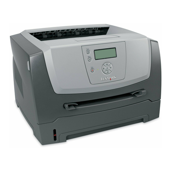
- Page 1 Edition: July 2, 2008 Lexmark™ E450dn 4512-630 • Table of contents • Start diagnostics • Safety and notices • Trademarks • Index Lexmark and Lexmark with diamond design are trademarks of Lexmark International, Inc., registered in the United States and/or other countries.
-
Page 2: Edition: July
Improvements or changes in the products or the programs described may be made at any time. Comments may be addressed to Lexmark International, Inc., Department D22A/032-2, 740 West New Circle Road, Lexington, Kentucky 40550, U.S.A or e-mail at ServiceInfoAndTraining@Lexmark.com. Lexmark may use or distribute any of the information you supply in any way it believes appropriate without incurring any obligation to you. -
Page 3: Table Of Contents
4512-630 Table of contents Table of contents ............iii Notices and safety information . - Page 4 4512-630 Media never picks ............2-22 Media occasionally mispicks or picks multiple sheets at once .
- Page 5 4512-630 EP SETUP ..............3-23 EP Defaults .
- Page 6 4512-630 Narrow media sensor removal ..........4-35 Operator panel removal .
-
Page 7: Notices And Safety Information
4512-630 Notices and safety information The following laser notice labels may be affixed to this printer. Laser notice The printer is certified in the U.S. to conform to the requirements of DHHS 21 CFR Subchapter J for Class I (1) laser products, and elsewhere is certified as a Class I laser product conforming to the requirements of IEC 60825-1. - Page 8 4512-630 Avisos sobre el láser Se certifica que, en los EE.UU., esta impresora cumple los requisitos para los productos láser de Clase I (1) establecidos en el subcapítulo J de la norma CFR 21 del DHHS (Departamento de Sanidad y Servicios) y, en los demás países, reúne todas las condiciones expuestas en la norma IEC 60825-1 para productos láser de Clase I (1).
- Page 9 4512-630 Laserilmoitus Tämä tulostin on sertifioitu Yhdysvalloissa DHHS 21 CFR Subchapter J -standardin mukaiseksi luokan I (1) - lasertuotteeksi ja muualla IEC 60825-1 -standardin mukaiseksi luokan I lasertuotteeksi. Luokan I lasertuotteita ei pidetä haitallisina. Tulostimen sisällä on luokan IIIb (3b) laser, joka on nimellisteholtaan 5 mW:n galliumarsenidilaser ja toimii 770 - 795 nanometrin aallonpituuksilla.
- Page 10 4512-630 Avís sobre el Làser Segons ha estat certificat als Estats Units, aquesta impressora compleix els requisits de DHHS 21 CFR, apartat J, pels productes làser de classe I (1), i segons ha estat certificat en altres llocs, és un producte làser de classe I que compleix els requisits d’IEC 60825-1.
- Page 11 4512-630 Notices and safety information...
- Page 12 4512-630 Service Manual...
-
Page 13: Safety Information
4512-630 Safety information • The safety of this product is based on testing and approvals of the original design and specific components. The manufacturer is not responsible for safety in the event of use of unauthorized replacement parts. • The maintenance information for this product has been prepared for use by a professional service person and is not intended to be used by others. - Page 14 4512-630 Sicherheitshinweise • Die Sicherheit dieses Produkts basiert auf Tests und Zulassungen des ursprünglichen Modells und bestimmter Bauteile. Bei Verwendung nicht genehmigter Ersatzteile wird vom Hersteller keine Verantwortung oder Haftung für die Sicherheit übernommen. • Die Wartungsinformationen für dieses Produkt sind ausschließlich für die Verwendung durch einen Wartungsfachmann bestimmt.
- Page 15 4512-630 Informació de Seguretat • La seguretat d'aquest producte es basa en l'avaluació i aprovació del disseny original i els components específics. El fabricant no es fa responsable de les qüestions de seguretat si s'utilitzen peces de recanvi no autoritzades. •...
-
Page 16: Preface
4512-630 Preface This manual contains maintenance procedures for service personnel. It is divided into the following chapters: General information contains a general description of the printer and the maintenance approach used to repair it. Special tools and test equipment are, as well as general environmental and safety instructions. Diagnostic information contains an error indicator table, symptom tables, and service checks used to isolate failing field replaceable units (FRUs). -
Page 17: General Information
1. General information is a monochrome laser printer designed for single users or small workgroups. The Lexmark™ E450dn This book contains information on E450dn. For more information on E250d and E250dn, see the 4512-220, -230 service manual. For information on E350d and 352dn, see the 4512-420, 430 service manual. -
Page 18: Overview Of The Operator Panel
4512-630 Overview of the operator panel The control panel consists of these items: • A 4-line, liquid crystal display (LCD) that can show both graphics and text • Eight buttons: Back, Menu, Stop, Select ( , and • Indicator light A label located on the inside front door shows the control panel buttons in your language. -
Page 19: Specifications
4512-630 Specifications Memory 4512-630 Item Lexmark E450dn Standard DRAM 64MB ✔ Optional SDRAM 32MB ✔ Optional SDRAM 64MB ✔ Optional SDRAM 128MB ✔ Optional SDRAM 256MB Maximum DRAM 320MB Optional flash memory 32MB Optional font cards (DBCS) Print quality 4512-630... -
Page 20: Media Trays And Supply Capacity
4512-630 Media trays and supply capacity 4512-630 Item Lexmark E450dn Available input trays ✔ 250-sheet tray ✔ 550-sheet option drawer 550-sheet tray optional Dust cover optional Toner and photoconductor Toner cartridge 3,000 standard pages ¹ High toner cartridge ² Photoconductor kit Up to 30,000 ¹... -
Page 21: Connectivity And Compatibility
4512-630 Connectivity and compatibility 4512-630 Item Lexmark E450dn Data stream emulations ✔ PCL 6 ✔ PostScript Level III Host Based Printing (HBP)/GDI Version 1 ✔ Host Based Printing (HBP)/GDI Version 2 ✔ PPDS HTML ✔ PDF (version 1.5) Compatibility Windows/Macintosh/Linux ¹... -
Page 22: Types Of Print Media
4512-630 Types of print media Ensure trays are properly loaded. Never mix media types within a tray. Input capacity Source Sizes Types Weight (sheets)² Input tray 1 A4, A5, A6³, JIS, B5, Paper, labels¹, 60—90 g/m 250 paper letter, legal, transparencies (16—24 lb) 50 labels¹... -
Page 23: Tips On Preventing Jams
4512-630 Tips on preventing jams Paper path *Measurements are approximate paper lengths (millimeters) **Sensors are measured at rotation/position which they are tripped Paper path 117.8 Manual feed sensor Upper end feed rolls 60.5 Input sensor 49.0 Transfer roll 110.7 Fuser 26.9 Fuser exit rolls Fuser exit sensor... -
Page 24: Tools
Have any exposed adhesive when the flap is in the sealed position Use only recommended media. Refer to the Card Stock & Label Guide available on the Lexmark Web site at www.lexmark.com for more information about which media provides optimum results for the current printing environment. -
Page 25: Acronyms
4512-630 Acronyms Autocompensator Mechanism (or paper feed) ASIC Application Specific Integrated Circuit Complete Bill Of Material Cyclic Redundancy Check DIMM Dual In-Line Memory Module EEPROM Erasable Electrically Programmable Read-Only Memory External Network Adapter Field Replaceable Unit Host Based Printing HVPS High Voltage Power Supply Liquid Crystal Diode Light Emitting Diode... - Page 26 4512-630 1-10 Service Manual...
-
Page 27: Diagnostics Information
4512-630 2. Diagnostics information Start CAUTION: Unplug power from the printer before connecting or disconnecting any cable, assembly, or electronic card. This is a precaution for personal safety and to prevent damage to the printer. Use the service error code, user status message, user error message, symptom table, service checks, and diagnostic aids in this chapter to determine the corrective action necessary to repair a malfunctioning printer. -
Page 28: Overview Of The Operator Panel And Menus
4512-630 Overview of the operator panel and menus The operator panel on your printer is a 4-line, back-lit, grayscale display that can show both graphics and text. The Back, Menu, and Stop buttons are located to the left of the display, the navigation buttons are located below the display, and the numeric pad is located to the right of the display. - Page 29 4512-630 Operator panel (Continued) Button Function The Up or Down buttons are used to move up and down lists. When navigating through a list using the Up or Down button, the cursor Navigation buttons moves one line at a time. Pressing the Down button at the bottom of the screen changes the screen to the next whole page.
-
Page 30: Diagram Of The Printer Menus
4512-630 Diagram of the printer menus The diagram shows the menu index on the operator panel and the menus and items available under each menu. Not all menus or selections will be available in all situations. These are accessed through the driver. Paper Menu Job Menu Finishing Menu... -
Page 31: Messages And Error Codes
4512-630 Messages and error codes User attendance messages The printer control panel displays messages describing the current state of the printer and indicates possible printer problems that must be resolved. This topic provides a list of all printer messages, explains what they mean, and tells how to clear the messages. -
Page 32: Performing Self Test
4512-630 User attendance messages (Continued) Message Action Load <src> with <Custom Type • Load the input source with the correct type and size media. Name> • Cancel the current job. Load <src> with <Custom String> Load <src> <size> Load <src> <type> <size> Maintenance Replace the maintenance items and, if necessary, reset the printer maintenance counter. -
Page 33: Resetting The Printer
4512-630 User attendance messages (Continued) Message Action Prog System Code The printer is programming new system code. Wait for the message to DO NOT POWER OFF clear and the printer to reset. Warning: Do not turn the printer off while this message is displayed. Ready Send a job to print. -
Page 34: Cartridge Error Messages
4512-630 Cartridge error messages Error Description Defective cartridge Unsupported print cartridge Invalid refill Paper jam error codes (200-series) Note: The Event log (see “EVENT LOG” on page 3-28) will list any of these errors that have occurred. Repeating jams or jam messages can be caused by any of the following: •... - Page 35 4512-630 Paper jam error codes (200-series) (Continued) Error Description 200.20 The media is too long over the manual feeder sensor. Possible causes include multi-sheet feed, media size (length) problem, pre-staged media in the tray. 200.22 FAILED SMALL GAP OR NO GAP JAM RECOVERY. Engine detected small gap or no gap at the manual feeder sensor, opened the gap by stopping the feed rolls, but never saw the leading edge of the second page at the input sensor.
- Page 36 4512-630 Paper jam error codes (200-series) (Continued) Error Description 201.27 Page at fuser nip before fuser reached acceptable operating temperature. Page arrived at fuser earlier than expected, so it was probably staged 202.00 Paper jam around exit sensor. 202.01 Exit sensor never broke on the trailing edge of the sheet at the exit sensor. 202.02 Exit sensor never broke from sheet ahead of page heading toward the exit sensor.
- Page 37 4512-630 Paper jam error codes (200-series) (Continued) Error Description 242.01 Took too long to ramp up dc feed motor 242.08 Received lots of dc feed interrupts before losing them 242.10 Second pick attempt failed from Tray 2 242.12 Second pick from manual feeder, tray 1, or feeder failed when media was in the source, other sheets were committed to the paper path.
-
Page 38: Service Error Codes
4512-630 Service error codes Service error codes are generally non-recoverable except in an intermittent condition when the printer can be put into POR to temporarily recover from the error condition. Service error codes (9xx) Error Description Engine software service errors 902.xx Engine software error Transfer service errors... - Page 39 4512-630 Service error codes (9xx) (Continued) Error Description 924.01 Open thermistor check failure. This applies to the fuser and belt fusers. 924.02 Open thermistor check failure. The ADC failed to converge. Possible noisy thermistor signal. This applies to the fuser and belt fusers. Fan service errors 927.00 Service fan error...
- Page 40 4512-630 Service error codes (9xx) (Continued) Error Description Transport motor service errors 936.01 No lock detected at normal motor start 936.02 No lock detected at motor start for motor ID 936.03 No halls detected at motor start 936.04 Failed to stop within timeout 936.05 Stall detected during speed control 937.00...
-
Page 41: Symptom Tables
4512-630 Symptom tables POST symptom table Symptom Action The main motor, cooling fan, and fuser do not come “Cover interlock switch service check” on page 2-18. “Operator panel service check” on page 2-21. POST completes, but LCD does not appear to be working. -
Page 42: Printer Symptom Table
4512-630 Printer symptom table Symptom Action Dead machine (no power). “Dead machine service check” on page 2-19. Fan noisy or fan not working. “Cooling fan service check” on page 2-18. “LVPS/HVPS service check” on page 2-20. Fuser parts melted. See“Fuser service check” on page 2-19. -
Page 43: Service Checks
4512-630 Service checks Service checks which involve measuring voltages on the LVPS/HVPS (low voltage power supply/ high voltage power supply board) should be performed with the printer positioned on its back side. Note: When making voltage readings, always use frame ground unless another ground is specified. -
Page 44: Cooling Fan Service Check
4512-630 Controller card service check (Continued) Action Verify main power to controller card LVPS/HVPS With the printer off, unplug the LPS/HVPS cable at J19 on the controller card. Verify grounds on pins 7, 12, and 14 for both the cable and the controller card. If any of these grounds are incorrect, check the cable for continuity. -
Page 45: Dead Machine Service Check
4512-630 Dead machine service check CAUTION: Check the AC line voltage. The voltage should be within the following limits: • 100 V ac (volts alternating current) — 127 V ac for the 110 V printer • 200 V ac — 240 V ac for the 220 V printer Action Unplug the printer. -
Page 46: Lvps/Hvps Service Check
4512-630 LVPS/HVPS service check Action LVPS portion of board Fuses that open typically indicate a faulty LVPS/HVPS. Disconnect the power cable, and open the LVPS/HVPS enough to test the switch. The switch will show continuity across the conductors with a meter when the switch is on. If the “Dead machine service check”... -
Page 47: Operator Panel Service Check
4512-630 Operator panel service check Inspect the operator panel cable for damage. Make sure the cable is plugged in securely. Run POST, and check “Power—On Self Test (POST) sequence” on page 2-1. each light for proper operation. See LCD Operator panel service check Action Operator panel (LED) Lights... -
Page 48: Media Picks But Stops Halfway Through The Printer
4512-630 Media picks but stops halfway through the printer Action Input/Duplex sensors Make sure the input sensors are working properly. (under print cartridge assembly) Check for a broken or stuck flag on the input sensors. Input sensor (manual) Make sure the cables are seated on the controller card at J23 (Tray 1 input) and J20 (manual input). -
Page 49: Media Skews
4512-630 Media skews Action Paper feed (pick tires) tray 1 Check tires for debris. If tires are new, try reversing each on its hub. Paper feed (pick tires) tray 2 Check side guides on Tray 1 and Tray 2. Guides set for a full stack of media may be Tray 1 too wide when the stack is short. -
Page 50: Print Quality Service Checks
4512-630 Print quality service checks Note: Ensure the cover closes tightly. A gap in the opening may allow light to expose the photoconductor resulting in a ‘dirty’ print. Extreme environmental conditions, temperatures, and humidity will affect the print quality. Using print quality test pages To help isolate print quality problems, like streaking, print test pages using the print quality test pages. -
Page 51: Black Page
4512-630 Black page Note: Incorrect laser exposure or incorrect charging of the photoconductor causes an all black page. Always verify the same results from a different print cartridge assembly and developer before proceeding. Action Toner electrodes (not a Check the three rearward electrodes below the print cartridge assembly for contamination FRU) or damage. -
Page 52: Partial Blank Image/White Spots (No Repeating Pattern)
4512-630 Partial blank image/white spots (no repeating pattern) Action Toner cartridge (not a Remove the toner cartridge assembly, and gently shake the assembly to evenly distribute FRU) the toner. Check to make sure that the laser light path is not blocked. If toner cartridge is low, try a new one. -
Page 53: Light Print
4512-630 Light print Action Toner cartridge (not a Make sure the toner cartridge and PC Kit are installed correctly and that the toner cartridge FRU) is not low on toner. If the problem continues, install a new toner cartridge. Recheck condition before replacing PC Kit, if necessary. Check the transfer roll for signs of toner buildup and contamination. -
Page 54: Solving Print Quality Problems
4512-630 Solving print quality problems Note: Refer to the print defects guide at the end of the manual for repeating defects. Print quality problems Problem Cause / action Light or blurred Light print characters. “Light print” on page 2-27. The toner cartridge may be getting low on toner: •... - Page 55 4512-630 Print quality problems (Continued) Problem Cause / action Toner smears or rubs • Toner is not being fused to the media. Replace the fuser. off the page. • Change the media texture setting in the driver. If special media is being used, such as card stock or labels, be sure to select the correct media type.
- Page 56 4512-630 Print quality problems (Continued) Problem Cause / action The printer is on and • Make sure the parallel or USB cable is not damaged and is firmly plugged into the indicates ready, but connector on the back of the printer. nothing prints.
-
Page 57: Printhead Service Check
4512-630 Print quality problems (Continued) Problem Cause / action Unexpected characters • Ensure correct printer driver is being used. print or characters are • Select hex trace mode to determine what the problem is. missing. • Restore factory defaults. • Make sure the parallel cable or USB cable is firmly plugged in at the back of the printer. Jobs are not printing, •... - Page 58 4512-630 2-32 Service Manual...
-
Page 59: Diagnostic Aids
4512-630 3. Diagnostic aids This chapter explains the tests and procedures to identify printer failures and verify repairs have corrected the problem. Accessing service menus There are different test menus that can be accessed during POR to identify problems with the printer. Diagnostics Mode 1. -
Page 60: Diagnostics Mode
4512-630 Diagnostics mode Entering Diagnostics mode Press and hold Turn on the printer. Release the buttons when Performing Self Test displays. Available tests The tests display on the operator panel in the order shown: Diagnostics mode tests REGISTRATION “REGISTRATION” on page 3-4 Bottom Margin Top Margin Left Margin... - Page 61 4512-630 Diagnostics mode tests (continued) DUPLEX TESTS (if installed) Quick Test “Quick Test (duplex)” on page 3-16 Top Margin “Top/Left Margin (duplex)” on page 3-16 Sensor Test “Sensor Test (duplex)” on page 3-17 “Duplex Feed 1” on page 3-17 Duplex Feed 1 INPUT TRAY TESTS “Feed Tests (input tray)”...
-
Page 62: Exiting Diagnostics Mode
4512-630 Diagnostics mode tests (continued) EP SETUP EP Defaults “EP Defaults” on page 3-23 Fuser Temp “Fuser Temperature (Fuser Temp)” on page 3-23 Transfer “Transfer” on page 3-23 “Print Contrast” on page 3-23 Print Contrast “Charge Roll” on page 3-23 Charge Roll “Gap Adjust”... - Page 63 4512-630 to select the margin setting you need to change, and press The Top margin sign/value pair blinks. This indicates it is the margin value being changed. T=xxx* B=xxx* L=xxx* R=xxx* to decrease or to increase the offset values, and press to confirm the value.
-
Page 64: Printhead Assembly Electronic Adjustment
4512-630 Printhead assembly electronic adjustment A step-by-step process to align a new printhead. Note: Before aligning the printhead electronically, first align the printhead mecahnically, if needed. See “Printhead assembly mechanical adjustment” on page 3-10 Press Go to print Step 1 test page. Step 1 printout (sample only;... - Page 65 4512-630 Press Go to print Step 2 test page. Step 2 printout (sample only; use actual sheet) Press to change the <BA> settings to the number beside the darkest portion of the vertical bar. Press and release to move to the <CA> settings on the right side of Step 2 test page. Press to change the <CA>...
- Page 66 4512-630 Press Go to print Step 3 test page. Step 3 printout (sample only; use actual sheet) Press to change the <BA> setting to the number beside the darkest portion of the vertical bar. Press and release to move to the <CA> settings on the right side of Step 3 test page. Press to change the <CA>...
- Page 67 4512-630 Press Go to print Visual alignment page. Visual alignment printout (sample only; use actual sheet) Verify that the overall darkest line across the page is “0.” If not, then run the alignment again. Turn the printer off to exit the printer alignment menu. Diagnostic aids...
-
Page 68: Printhead Assembly Mechanical Adjustment
4512-630 Printhead assembly mechanical adjustment A printhead needs to be correctly positioned after it has been removed. Align it to the frame or use the same position as the removed printhead. An indicator is located at the front right-hand screw for reference. Note: Skew is caused by a sheet being fed through the printer while misaligned. - Page 69 4512-630 If the grid lines of the right flap align below the corresponding lines on the left flap, adjust the printhead clockwise relative to the printer and recheck. (See the left side of the figure below.) If the grid lines of the left flap align below the corresponding lines of the right side, adjust the printhead counterclockwise.
-
Page 70: Quick Test
4512-630 Quick Test The Quick Test contains the following information: • Print registration settings • Alignment diamonds at the top and bottom • Horizontal lines to check for skew • General printer information, including current page count, installed memory, serial number, and code level. To print the Quick Test page: Note: Print the Quick Test Page on letter or A4 paper. -
Page 71: Print Tests
4512-630 PRINT TESTS Input source tests The purpose of the diagnostic Print Tests is to verify that the printer can print on media from each of the installed input options. The contents of the Print Test Page varies depending on the media installed in the selected input source. -
Page 72: Hardware Tests
4512-630 HARDWARE TESTS Select the following Hardware Tests from this menu: • Panel Test • Button Test • DRAM Test • ROM Memory Test • Parallel Wrap (if available) • Serial Wrap (if available) Panel Test This test automatically toggles each pixel of the operator panel through every contrast level beginning with the darkest and on to the brightest. -
Page 73: Parallel Wrap Tests
4512-630 Parallel Wrap tests This test is used with a wrap plug to check operation of the parallel port hardware. Each parallel signal is tested. Use Parallel Wrap for the standard parallel port, Parallel 1 Wrap if a parallel port is available by PCI slot 1, or Parallel 2 Wrap if a parallel port is available by PCI slot 2. -
Page 74: Duplex Tests
4512-630 DUPLEX TESTS Quick Test (duplex) This test prints a duplex version of the Quick Test that can be used to verify that the correct placement of the top margin on the back side of a duplex page. You can run one duplexed page (Single), or continue printing duplexed pages (Continuous) until Stop ( ) is pressed. -
Page 75: Sensor Test (Duplex)
4512-630 Sensor Test (duplex) This test is used to determine whether or not the duplex sensors and switches are working correctly. The test allows you to actuate the duplex input sensor located in the back part of the duplex unit and the duplex exit sensor located in the return paper path. -
Page 76: Input Tray Tests
4512-630 INPUT TRAY TESTS Feed Tests (input tray) This test lets the servicer observe the paper path as media is feeding through the printer. A blank sheet of paper feeds through the printer as the laser turns off during this test. The paper is placed in the output bin. To run the Input Tray Feed Tests: Select Feed Tests from INPUT TRAY TESTS. -
Page 77: Output Bin Tests
4512-630 OUTPUT BIN TESTS Feed Tests (output bins) Use these tests to verify that media can be fed to a specific output bin. Media is fed from the default input source to the selected output bin. No information is printed on the media fed to the output bin because the printhead is not engaged during this test. -
Page 78: Base Sensor Test
4512-630 BASE SENSOR TEST This test is used to determine if the sensors located inside the printer are working correctly. To run the Base Sensor Test: Select BASE SENSOR TEST from the DIAGNOSTICS menu. The following sensors are listed: • Exit–Exit sensor •... -
Page 79: Printer Setup
4512-630 PRINTER SETUP Defaults US/Non-US defaults changes whether the printer uses the US factory defaults or the non-US factory defaults. The settings affected include paper size, envelope size, PCL symbol set, code pages, and units of measure. Warning: Changing this setting resets the printer to factory defaults, and data may be lost. It cannot be undone. Page Count The page count can only be viewed and cannot be changed. -
Page 80: Configuration Id
4512-630 Configuration ID The two configuration IDs are used to communicate information about certain areas of the printer that cannot be determined using hardware sensors. The configuration IDs are originally set at the factory when the printer is manufactured, however the servicer may need to reset Configuration ID 1 or Configuration ID 2 whenever you replace the system board. -
Page 81: Ep Setup
4512-630 EP SETUP EP Defaults This setting is used to restore each printer setting listed in EP SETUP to its factory default value. Sometimes this is used to help correct print quality problems. To restore EP Defaults: Select EP Defaults from EP SETUP. Select Restore to reset the values to the factory settings, and select Do Not Restore to exit without changing the settings. -
Page 82: Event Log
• Time and date stamps • Page counts for most errors • Additional debug information in some cases The printed event log can be faxed to Lexmark or your next level of support for verification or diagnosis. 3-24 Service Manual... -
Page 83: Clear Log
4512-630 To print the event log: Select Print Log from EVENT LOG. Press Back ( to return to EVENT LOG. Clear Log Use Clear Log to remove the current information in the Event Log. This affects both the viewed log and the printed log information. -
Page 84: Configuration Menu (Config Menu)
4512-630 Configuration menu (CONFIG MENU) Entering Configuration Menu Turn off the printer. Press and hold Turn on the printer. Release the buttons when Performing Self Test displays. The message CONFIG MENU displays on the top line of the operator panel. Available menus Maint Cnt Value “Maintenance page count (Maint Cnt Value)”... -
Page 85: Maintenance Page Count (Maint Cnt Value)
4512-630 Maintenance page count (Maint Cnt Value) The current value for the maintenance page counter is displayed. This counter tracks printer usage. A print job containing a single page increments the counter by one and a duplex page by two. At 300,000, the customer is reminded that the printer requires scheduled maintenance. -
Page 86: Ppds Emulation
4512-630 PPDS Emulation This menu item allows the user to enable or disable PPDS emulation data stream. When this setting is enabled, the following settings are also changed: • SmartSwitch settings for each port are turned off. • The printer language is changed to PPDS Emulation. Users can still switch languages on the operator panel and through the PJL data stream. -
Page 87: Change Prompts
4512-630 Change Prompts The value of this setting determines if the device displays any of the Change prompts. Reduced Curl This setting will cause the engine throughput to be significantly reduced if it is enabled. This mode will only be used if the media being printed is “Paper.”... - Page 88 4512-630 3-30 Service Manual...
-
Page 89: Repair Information
4512-630 4. Repair information Warning: Read the following before handling electronic parts. Handling ESD-sensitive parts Many electronic products use parts that are known to be sensitive to electrostatic discharge (ESD). To prevent damage to ESD-sensitive parts, follow the instructions below in addition to all the usual precautions, such as turning off power before removing logic cards: •... -
Page 90: Front Access Cover Removal
Extract the cable, and unhook the access cover by pressing the right hinge to the right until it can be lifted up and away from its pivot. Relax the hinge above the pivot. In the same manner, move the left hinge from its pivot point. Lexmark™ E450dn... - Page 91 4512-630 Tilt the front cover down, and disconnect it on the left side from the link. Warning: Make sure that the link is not bent or pulled out farther than normal. Otherwise, the toner cartridge coupler may become dislodged. Remove the front access cover. Repair information...
-
Page 92: Left Side Cover Removal
Position the printer with the left rear corner hanging over the edge of the table. Swing the cover open. Lift the top rear of the cover over the pivot point, and drop the cover away from the printer. Lexmark™ E450dn... -
Page 93: Right Side Cover Removal
4512-630 Right side cover removal Remove Tray 1. Open the front access cover. Open the rear door. Release the latches (A), and swing the cover open. Position the printer with the right rear corner hanging over the edge of the table. Lift the top rear of the cover over the pivot point, and drop the cover away from the printer. -
Page 94: Rear Cover Removal
Lift the rear cover, unhooking it from the frame at the bottom, and remove. Note: In re-installation, check to make sure that the fuser ground cable is routed out of the way and is not pinched or damaged. Lexmark™ E450dn... -
Page 95: Top Cover Removal
4512-630 Top cover removal Remove the right side cover. See “Right side cover removal” on page 4-5. Remove the left side cover. See “Left side cover removal” on page 4-4. Open the rear door. Remove the two screws (A) from the two front corners on the top cover, the two screws (B) from the two rear corners on the top cover, and the screw (C) on the left side. - Page 96 Verify the proper alignment of the top cover with the paper exit guide along the mating edges at the rear of the exit tray. • Verify that the rollers in the top cover contact the exit guide rollers at the top rear. There are arrows under the top cover to verify the location of the rollers. Lexmark™ E450dn...
-
Page 97: Auto Comp Removal
4512-630 Auto comp removal Remove the duplex. See “Duplex removal” on page 3-18. Remove the auto comp clutch. See“Auto comp clutch removal” on page 3-10. Use a spring hook or a small screwdriver to rotate the latch toward the bottom of the printer until it is pointing downward. -
Page 98: Auto Comp Clutch Removal
“Main motor drive removal” on page 3-28. Remove the screws (A). Note: Resistance to loosening the screw may have to be applied to the shaft. Use a finger or small screwdriver against the coupler behind the clutch. Remove the auto comp clutch. 4-10 Lexmark™ E450dn... -
Page 99: Auto Comp Drive Shaft Assembly Removal
4512-630 Auto comp drive shaft assembly removal Remove the auto comp clutch. See “Auto comp clutch removal” on page 3-10. Use a spring hook or a small screwdriver to dislodge the arm of the shaft bushing, and rotate the arm counterclockwise as far as it will go. -
Page 100: Bezel Removal
Open the front access cover. Remove the two screws (A). Lift the lower edge of the shield, slide it to the right, and remove. Release the four inner latches (B). Remove the bezel and lens while the door remains open. 4-12 Lexmark™ E450dn... -
Page 101: Controller Card Removal
4512-630 Controller card removal Warning: • Always touch a ground before touching the card. • Handle the card carefully by the edges. • Never replace the operator panel and controller card at the same time without a successful POR in between. - Page 102 Re-installation note: When replacing the controller card, make sure to route all of the cables through the correct shield opening. Make sure that the ground wire that is being held by the front, upper screw is in the correct location before installing. 4-14 Lexmark™ E450dn...
-
Page 103: Cover Open Sensor Removal
4512-630 Cover open sensor removal Remove Tray 1. Open the front cover. “Right side cover removal” on page 3-5. Open the right side cover. See steps 1 and 2 of Remove the controller card cover. Loosen the one screw (A) from the shield that protects the sensor. Disconnect the cable from J6 on the controller card. -
Page 104: Developer Drive Coupling Assembly Removal
Place the machine on its right side. Note: Be sure to protect the machine from marring. Remove the six screws (A), the machine screw (B), and the ground cable screw (C). Lift the main motor drive, and disconnect the motor cable (D). 4-16 Lexmark™ E450dn... - Page 105 4512-630 Remove the coupling spring (E). Remove the developer drive coupling (F). 4-17 Repair information...
-
Page 106: Duplex Removal
Remove the screw (C) opposite from screw (B) on the other side of the printer. Note: The ground cable is attached to screw (C). When re-installing, be sure to reconnect the ground cable. Remove the media level indicator. See “Media level indicator removal” on page 3-33. 4-18 Lexmark™ E450dn... - Page 107 4512-630 Remove the six screws (D). Lift the right side (opposite the coupler) and remove the duplex. Note: At re-installation, before tightening the screws, locate the duplex unit against the left side frame. (Left side relative to the picture above.) 4-19 Repair information...
-
Page 108: Duplex Gear Drive
Remove the duplex coupling and gears (A) (the screw and plastic retainer). Remove the duplex coupling (B) and mating link. Note: The link (not shown) that connects the duplex and duplex coupling is part of this FRU as well as the duplex FRU. 4-20 Lexmark™ E450dn... -
Page 109: Fan Removal
4512-630 Fan removal Open the right side cover. See steps 2 through 4 of “Right side cover removal” on page 3-5. Remove the two screws (A) holding the fan to the side frame. Unplug the cable from J4 on the controller card. Note: Be sure to remove the toroid before removing the cables. -
Page 110: Fuser Removal
Remove the two screws (A) and the one machine screw (B) that secures the ground cable. Disconnect the thermistor cable above the fuser. Remove the controller card cover. Disconnect the exit sensor cable from J11 on the controller card. Disconnect the fuser power cable above the fuser. 4-22 Lexmark™ E450dn... - Page 111 4512-630 Unlatch the fuser (see (A) and (B) in the second photo below), and remove. Reinstallation note: • Be sure to reroute the cables back through their retainers. • If the printer has been moved following the removal of the fuser, verify that the cross shaft behind the fuser is in place.
-
Page 112: Fuser Power Cable Removal
Remove the four screws (A), the machine screw (flange head) (B), and the machine screw (button head) (C). Use the hook end of a spring hook to disconnect the fuser power cable from the LVPS/HVPS side. Note: The connector latch (D) is toward the side frame as shown. 4-24 Lexmark™ E450dn... -
Page 113: Link Developer Drive And Access Door Removal
4512-630 Link developer drive and access door removal Remove the main motor drive. See “Main motor drive removal” on page 3-28. Remove the coupling assembly. See “Developer drive coupling assembly removal” on page 3-16. “Front access cover removal” on page 3-2. -
Page 114: Lvps/Hvps Card Assembly Removal
Remove the four screws (A), the machine screw (B) and the machine screw (C). Unhook the red cable (D) located in the left side frame. Lift the metal cover so the connecting cables (E) and (F) can be unplugged on the side shown. 4-26 Lexmark™ E450dn... - Page 115 4512-630 Rotate the assembly, and unplug the remaining cables. Remove the assembly. Re-installation note: When re-installing the LVPS/HVPS assembly: • Be sure to locate the rear flange of the card bracket inside of the shield prior to rotating the card assembly into final position.
-
Page 116: Main Motor Drive Removal
IMPORTANT: The ground strap (held by screw B) is not included in the main motor drive FRU. Be sure to remove this strap, and install it in the new drive. Lift the motor end, and disconnect the main motor cable (D). Lift the gear assembly, and remove the developer drive spring (E). 4-28 Lexmark™ E450dn... - Page 117 4512-630 Rotate the motor drive counterclockwise until the two plastic links can be separated. Remove the main motor drive. 4-29 Repair information...
-
Page 118: Manual Feed Sensor Removal
Hook the spring hook to the connector, and pull it through the opening. • Place the sensor into position, and reconnect the cable on the controller card. • Using the spring hook, be sure to reroute the cable through the three retainers between the sensor and side frame. 4-30 Lexmark™ E450dn... -
Page 119: Manual Paper Feed Clutch
4512-630 Manual paper feed clutch Open the left side cover. See “Left side cover removal” on page 4-4 for more information. Tilt the printer onto its right side, and remove the six screws (A), the screw (B), and the ground cable screw (C). -
Page 120: Manual Feed Solenoids
Extract the solenoid cable to a point close to the left side as possible. “Main motor drive removal” on page 3-28. Remove the main motor drive. See Remove the auto comp clutch. See “Auto comp clutch removal” on page 3-10. Remove the three screws (A). Remove the manual feed solenoids. 4-32 Lexmark™ E450dn... -
Page 121: Media Level Indicator Removal
4512-630 Media level indicator removal Remove the left side cover. See “Left side cover removal” on page 3-4. Turn the printer onto its top. (Be careful to protect the covers.) Unhook and remove the spring (A). Unhook the link (B) from the indicator level. 4-33 Repair information... - Page 122 Unsnap the shaft from its pivot, which is attached to the back of the LVPS/HVPS shield (D). Align the link end of the shaft with the opening in the side frame, and remove the shaft and spring anchor (E). 4-34 Lexmark™ E450dn...
-
Page 123: Narrow Media Sensor Removal
4512-630 Narrow media sensor removal Remove the top cover. See “Top cover removal” on page 3-7. Turn the top cover upside down. Remove the ground strap screw (A) and the ground strap. Remove the narrow media sensor. 4-35 Repair information... -
Page 124: Operator Panel Removal
Warning: Do not replace the operator panel and the controller card at the same time. Each card contains the printer settings. When either of these cards is new, it obtains its settings from the other card. Critical factory settings are lost when both are new and replaced at the same time. 4-36 Lexmark™ E450dn... -
Page 125: Paper Exit Guide Assembly Removal
4512-630 Paper exit guide assembly removal Remove the rear cover. See “Rear cover removal” on page 3-6. Remove the one screw above the reversing solenoid. See “Top cover removal” on page 3-7. Remove the three screws (A). Lift the back of the top cover (right side in photo) to prevent the gears on the assembly from touching other items while removing, especially the fuser mounting bracket. -
Page 126: Paper Feed Rollers (Autocompensator Tires) Removal
Notice the direction of the points on the edge. Those points should be directed in the paper feed direction as shown. Make sure the new paper feed rollers are captured between the rims of the plastic hub. If the orientation is questionable, run Print Quality sheets, and check for skew. 4-38 Lexmark™ E450dn... -
Page 127: Paper Input And Duplex Sensor Removal
4512-630 Paper input and duplex sensor removal Remove the duplex unit. See “Duplex removal” on page 3-18. Remove screws (A) holding the two sensors. Remove the sensor assembly. Note: Be sure to secure cables in retainers when installing the new assembly. The solenoid cable should be installed on top of the sensor cables. -
Page 128: Printhead Removal
Be sure to place the toroid back over the cables. • Mechanically adjust the printhead, if necessary. See “Printhead assembly mechanical adjustment” on page 3-10. • Electronically adjust the printhead. This is a necessary step. See “Printhead assembly electronic adjustment” on page 3-6. 4-40 Lexmark™ E450dn... -
Page 129: Reversing Solenoid Removal
4512-630 Reversing solenoid removal Remove the top cover. See “Top cover removal” on page 4-7. Remove the controller card shield. (Loosen the four screws, and slide.) See “Right side cover removal” on page 3-5. Disconnect the cable from J9 (DP REV SOL) on the controller card. Remove the two screws (A). -
Page 130: Transfer Roll Removal
If the old springs are moved, feel the base of the springs to assure that they are on the posts. The top of the springs must be captured in the bearings of the transfer roll. 4-42 Lexmark™ E450dn... -
Page 131: Tray 2 Auto Comp Tire Removal
4512-630 Tray 2 auto comp tire removal Gently pull the rubber tire loose from the wheel, and replace it with a new tire. Note: Look at the nap of the tire, and orient the tire for highest friction when picking the paper. 4-43 Repair information... -
Page 132: Upper Front Frame Group Removal
Lift the right side to align the flat on the guide shaft with the opening. Slide the shaft through the opening. Slide the cover to the right to free the left side, and remove the front cover guide. 4-44 Lexmark™ E450dn... - Page 133 4512-630 Installation note: Move the printer so the front hangs over the front edge of the work surface. Anchor the left spring on its rear post and maintain tension on it while snapping the assembly into position on the left side. Use the spring hook from below the printer to anchor the front of the spring.
-
Page 134: Wear Strip Removal (Tray 1)
Use a spring hook to unfasten each of the anchors on the back of each strip. Remove the strip from inside the tray. Wear strip removal (tray 2) Pull up the strip with the spring hook to free it at the top. Lift the strip out. 4-46 Lexmark™ E450dn... - Page 135 4512-630 Note: When replacing the strip: • Push the strip up with your thumb to make sure that the strip is in place. • Turn the tray over so that you are looking at the bottom of the strip. Using the spring hook, check to make sure that the end of the strip is secure and the strip is fastened tightly.
- Page 136 4512-630 4-48 Lexmark™ E450dn...
-
Page 137: Locations And Connections
4512-630 5. Locations and connections Locations Front view Paper support 150-Sheet output bin Control panel Front door Manual feeder 250-Sheet tray 550-Sheet drawer (optional) Rear view Locations and connections... -
Page 138: Controller Card Connector Pin Values
4512-630 Controller card connector pin values Note: See the wiring diagram at back of book. These values were measured with all connections made (plugged) or with only one connector at a time unplugged to expose the pins. Always disconnect and connect with the printer power off. Otherwise, the values below may not match. - Page 139 4512-630 Connector Pin # Value Value Comments cableplugged cable unplugged (if different) 5 V dc LSU (HSYNC) 2, 3 Signal Ground Signal 3.2 V dc Main motor Ground 5 V dc 24 V dc Less than 24 V dc Signal LVPS/HVPS Ground 8, 9...
-
Page 140: Connectors
4512-630 Connectors System board Connector Pin no. Signal J1 USB Port Ground USB +5 V dc USB D- USB D+ Ground Ground Service Manual... -
Page 141: Preventive Maintenance
Damaged, missing, or altered covers, especially in the area of the top cover and the power supply cover • Possible safety exposure from any non-Lexmark attachments Lubrication specifications FRUs are typically lubricated as needed from the factory. If not, lubricate only when parts are replaced or as needed, not on a scheduled basis. - Page 142 4512-630 Service Manual...
-
Page 143: Parts Catalog
• PP: (Parts Packet) in the parts description column indicates the part is contained in a parts packet. • Model information used in the parts catalog. Machine type Description and model 4512-630 Lexmark E450dn Parts Catalog... -
Page 144: Assembly 1: Covers
4512-630 Assembly 1: Covers Service Manual... - Page 145 4512-630 Assembly 1: Covers Asm- Part Units/ Units/ Description Index number mach 1–1 40X5069 Top cover assembly (includes narrow media sensor) 40X5068 Top cover right flag 40X2839 Rear upper and lower cover assembly 40X2858 Legal extender dust cover 40X2837 Right side cover 40X2843 Optional media drawer assembly 40X2844...
-
Page 146: Assembly 2: Electronics
4512-630 Assembly 2: Electronics Service Manual... - Page 147 4512-630 Assembly 2: Electronics Asm- Part Units/ Units/ Description Index number mach 2—1 40X2803 LSU, E350d/E352dn/E450dn (printhead) 40X2800 Fuser assembly, 110 V 40X2801 Fuser assembly, 220 V 40X2802 Fuser assembly, 100 V 40X2833 Miscellaneous cable assemblies Thermistor LVPS/HVPS to controller card Main drive gear assembly (motor to controller card) Fuser power (LVPS to fuser) 40X2823...
-
Page 148: Assembly 3: Frame
4512-630 Assembly 3: Frame Service Manual... - Page 149 4512-630 Assembly 3: Frame Asm- Part Units/ Units/ Description Index number mach 3—1 40X2834 Media exit guide assembly 40X2822 Transfer roll, bearings, gear, spring (CBM) 40X2858 Legal extender dust cover 40X2850 Screws, miscellaneous TP2NCX3X6PF-Ni TP2C-4.0+8PF-Ni M3.0*0.5+6PF-Ni M3.0*0.5+4PF-Ni M3.5*0.6+6P-Ni 40X2853 ACM drive shaft assembly 40X2841 Complete duplex assembly 56P1820...
-
Page 150: Assembly 4: Options
4512-630 Assembly 4: Options Asm- Part Units/ Units/ Description Index number mach 40X1364 32MB SDR DIMM 40X1365 64MB SDR DIMM 40X1366 128MB SDR DIMM 40X1367 Parallel cable, packaged (3 m) 40X1368 USB cable, packaged (2 m) 40X1371 256MB SDR DIMM 40X1564 32MB flash card assembly 40X1512... -
Page 151: Index
4512-630 Index 3-23 Fuser Temp 3-23 Gap Adjust abbreviations 3-23 Print Contrast acronyms 3-23 Transfer 4-38 autocompensator tires EVENT LOG 3-25 Clear Log 3-24 3-14 Display Log Button Test 3-24 Print Log buttons exiting accessing service menus 3-14 HARDWARE TESTS Button Test 3-14 Button Test... - Page 152 4512-630 LED–E238/E240(n) overview 3-14 Panel Test parts catalog output bin sensor tests 4-21 removal 3-19 standard bin 2-18 service check frame, parts catalog fuser page count parts catalog 3-21 Page Count 4-22 removal 3-21 permanent page count 2-19 service check 3-14 Panel Test panel, control...
- Page 153 4512-630 4-24 fuser power cable 4-26 LVPS/HVPS card assembly 4-38 tires, removal 4-37 paper exit guide assembly tools 4-38 paper feed rollers Top Margin 4-40 printhead 3-16 duplex procedures simplex (front side) 4-41 toner level sensor– transfer roll 4-42 transfer roll parts catalog 4-42 removal...
- Page 154 4512-630 Service Manual...
-
Page 155: Part Number Index
4512-630 Part number index Description Page 1319128 Parallel wrap plug - - - - - - - - - - - - - - - - - - - - - - - - - - - - - - - - - - - - - - - - - - - - - - - - - - - - - - - - - - - - - 3-15 40X0270 Power cord, 1.77M (straight)–Japan - - - - - - - - - - - - - - - - - - - - - - - - - - - - - - - - - - - - - - - - - - - - - - - -... - Page 156 4512-630 40X2836 Left side cover - - - - - - - - - - - - - - - - - - - - - - - - - - - - - - - - - - - - - - - - - - - - - - - - - - - - - - - - - - - - - - - - 40X2837 Right side cover - - - - - - - - - - - - - - - - - - - - - - - - - - - - - - - - - - - - - - - - - - - - - - - - - - - - - - - - - - - - - - - 40X2838...
- Page 158 Print defects guide Page 1 of 1 Print defects guide Defects often repeat down a page. In such cases, matching the defect frequency to one of the sets of vertical lines below can help identify the particular part that may be causing the defect. For example, the distance between these two marks represents a repeating defect caused by the toner cartridge.
Need help?
Do you have a question about the E450DN - E 450dn B/W Laser Printer and is the answer not in the manual?
Questions and answers