
Related Manuals for Emerson Liebert NXL 250-400kVA


Summary of Contents for Emerson Liebert NXL 250-400kVA
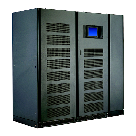
- Page 1 Liebert ® ™ Operation and Maintenance Manual – 250-400kVA, 60Hz, Three Phase Single-Module AC Power For Business-Critical Continuity™...
-
Page 2: Battery Cabinet Precautions
Call 1-800-LIEBERT before moving battery cabinets (after initial installation). Contacting Liebert for Support Contact Emerson Network Power Liebert Services for information or repair service in the United States at 1-800-LIEBERT (1-800-543-2378). For repair or maintenance service outside the 48 contiguous United States, contact Liebert Services, if available in your area. -
Page 3: Table Of Contents
ATTERY ABINET RECAUTIONS IMPORTANT SAFETY INSTRUCTIONS ......... .1 . - Page 4 Liebert Services ............32 3.2.1 Professional Startup .
- Page 5 Figure 1 Typical UPS system one-line diagram ..........2 Figure 2 Main component locations .
-
Page 7: Save These Instructions
MPORTANT AFETY NSTRUCTIONS SAVE THESE INSTRUCTIONS This manual contains important instructions that should be followed during installation and mainte- nance of your Liebert NXL UPS and batteries. WARNING Risk of electric shock. Can cause equipment damage, injury or death. Exercise extreme care when handling UPS cabinets to avoid equipment damage or injury to personnel. -
Page 8: Battery Cabinet Precautions
NTRODUCTION General Description The Liebert NXL UPS provides continuous, high-quality AC power to your business-critical equip- ment, such as telecommunications and data processing equipment. The Liebert NXL UPS supplies power that is free of the disturbances and variations in voltage and frequency common to utility power, which is subject to brownouts, blackouts, surges and sags. -
Page 9: Bypass Mode
1.2.2 Bypass Mode When the Liebert NXL is in bypass mode, the load is directly supported by utility power and is with- out battery backup protection. The Liebert NXL’s inverter and bypass static switch will shift the load from the inverter to bypass mode without an interruption in AC power if the inverter is synchronous with the bypass and any of the following occurs: •... - Page 10 • Load Bus Synchronization—The Load Bus Sync (LBS) option keeps two independent UPS sys- tems (and therefore their critical load buses) in sync, even when the modules are operating on bat- teries or asynchronous AC sources. This means that critical loads connected to both load buses can switch seamlessly between the two.
-
Page 11: Operation
PERATION The Liebert NXL UPS is equipped with a microprocessor-based display touchscreen designed for con- venient and reliable operation. The display is driven by an easy-to- follow, menu-prompted software. Features The Liebert NXL interface display enables the operator to perform such tasks as: •... -
Page 12: Figure 3 Main Display Screen, Typical
Figure 3 Main Display Screen, typical Mimic Display Active Event Window Figure 4 Mimic display BYPASS Bypass Input Freq 0.0Hz INPUT Input Power Freq 0.0Hz Battery BATTERY 1 OF 4 Block Voltage Disable Temp Disable BIS1 Bypass Input—Displays the bypass input voltage and the bypass input frequency. The bypass cir- cuit breaker (BFB) is to the right of this block. -
Page 13: Figure 5 Monitor/Mimic Display Example: Normal Power Flow
Figure 5 Monitor/mimic display example: Normal power flow Green – Normal Orange – Marginal Gray – Absent Black – Unknown Figure 6 Monitor/mimic display example: Utility fail Green – Normal Orange – Marginal Gray – Absent Black – Unknown Operation... -
Page 14: Figure 7 Monitor/Mimic Display Example: Load On Bypass, Ups On
Figure 7 Monitor/mimic display example: Load on bypass, UPS On Green – Normal Orange – Marginal Gray – Absent Black – Unknown Figure 8 Monitor/mimic display example: Load on bypass, UPS module off Green – Normal Orange – Marginal Gray – Absent Black –... -
Page 15: Touchscreen Navigation
Navigation Touchscreen 2.2.1 Main Display Screen Several menu items can be accessed from the main display screen (see Figure 3). These menu items are detailed in subsequent sections. Figure 9 Menu tree Configurations Help Menu Metering Rating System Settings Silence Adjustable Reset Setpoints... -
Page 16: Configurations Menu
2.2.2 Configurations Menu Rating This menu item will display a popup showing the following parameters (see Figure 10). These parameters are entered during commissioning when the UPS is installed. • Nominal Input Voltage • Nominal Bypass Voltage • Nominal Output Voltage •... -
Page 17: Figure 11 System Settings Parameters
User Settings System Settings These display settings can be changed from the touchscreen. Press the box to the left of each parame- ter to bring a popup window that will allow the parameter to be changed. • Backlight Brightness—High or Low (default: Low) •... -
Page 18: Figure 12 Adjustable Setpoints Parameters
Adjustable Setpoints These warning and alarm settings can be changed from the touchscreen. Press the box to the left of each parameter to bring a popup window that will allow the parameter to be changed. Max Load Alarm • Phase A (%)—10% to 105% (default: 95%) •... -
Page 19: Battery Test
Battery Test • Auto Test—Enable/Disable (default: disabled) • Test Cycle, weeks—1 to 26 (default: 13 weeks) • Time of day, hh:mm—Set Hour and Minute; sets the start time of the automatic battery test • Start Date, mm dd, yyyyy—Set Month, Day and Year •... -
Page 20: Status Reports Menu
Event Management This menu item permits changing how the Liebert NXL handles Alarms, Faults and Status informa- tion. Each event can be configured for the following: • Latch (yes/no)—Event stays active in the event window, even if the fault condition has been cleared, until user acknowledges it by pressing the “Reset”... -
Page 21: Shutdown Menu
2.2.5 Shutdown Menu This menu permits shutting down the UPS and individual devices. Figure 15 Shutdown menu Open Trap—Open the input trap filter Open MBD/BCB—Opens the associated MBD or BCB breaker UPS—Turns off inverter, rectifier and trips all battery breakers. Transfers to bypass, if available. NOTE The following popup window is displayed when the UPS is about to be shut down. -
Page 22: Transfer Menu
2.2.6 Transfer Menu This menu permits switching between UPS and Bypass mode. A graph in the multipurpose window shows if the UPS is in synch with the bypass. If the UPS and bypass are in synch, pressing Bypass will switch the UPS to Bypass mode. Pressing UPS will switch back to Normal (Inverter) Mode (see Figure 18). -
Page 23: Battery Management Menu
2.2.7 Battery Management Menu This menu permits configuring battery settings. Time Remaining Graph—Displays the time remaining graph in the multipurpose window; plot the battery voltage against elapsed time during a Battery Discharge Cycle (see Figure 19). Figure 19 Time remaining display Manual Battery Test—Start/Stop Manual Battery Equalize—For Service only. -
Page 24: Figure 20 Battery Cycle Monitor
Figure 20 Battery cycle monitor Display summary (see Figure 21) • Battery Commission Date/Time • Last Battery Discharge Date/Time • Active Battery Discharge Time • Active Battery Amp Hours • Active Battery KW • Total Number of Discharges Figure 21 Battery cycle monitor summary Operation... -
Page 25: Metering
Clear Log—This command resets the Date of First Discharge Cycle. A dialog box will warn that the data will be permanently lost and should downloaded before proceeding (see Figure 22). Figure 22 Battery cycle monitor—clear log 2.2.8 Metering This button will place the metering tables in the multipurpose window. 2.2.9 Help This button will display the help menu. -
Page 26: Ok To Transfer
2.3.2 OK to Transfer The OK to Transfer status message will be displayed when the bypass line and UPS output power are both available, their voltage, frequency and phase synchronization are matched within specifications, and the Static Switch Disconnects are closed (ON). An alarm message may be displayed to indicate Load On Bypass (Figure 24). -
Page 27: Input Power Failure-Load On Battery
2.3.3 Input Power Failure—Load on Battery If the utility AC power source fails or is outside the acceptable range, the battery plant becomes the power source for the UPS module inverters. The UPS continues to supply power to the critical load and also to the UPS controls. -
Page 28: Off Battery
2.3.4 Off Battery The battery plant can be disconnected from the UPS, if required for battery maintenance, by opening the module battery disconnect (MBD) circuit breaker. In this situation the UPS module will continue to supply conditioned power to the critical load, but if input power fails the UPS system cannot supply power to the load. -
Page 29: Remote Emergency Power Off
2.3.6 Remote Emergency Power Off The Remote Emergency Power Off (REPO) mode will transfer the critical load to the bypass line and remove power from all UPS module components except the controls, bypass circuit breaker and the static switch. The Remote Emergency Power Off control is a user-provided switch located remotely from the UPS system. -
Page 30: Startup Procedure
2.4.1 Startup Procedure CAUTION The following procedure provides power to the critical load distribution system. Verify that the critical load distribution is ready to accept power. Make sure that personnel and equipment are ready for the critical load distribution system to be energized. If your installation includes a Maintenance Bypass, you may already be supplying power to the criti- cal load equipment through the Maintenance Bypass. -
Page 31: Figure 30 Startup Commands
e. The “Close CB1” message will appear. Close CB1 (see Figure 2) The “Press OK to Issue Rectifier On Command” message will appear. Press “OK” This will start the UPS’ rectifier. Load is still on internal bypass. g. The “Press OK to Issue Inverter On Command” message appears. Press “OK” The motorized Module Output Breaker (CB2) will close. -
Page 32: Load Transfer Procedures
2.4.2 Load Transfer Procedures Changing the load from the UPS system to the UPS bypass is called a transfer. Changing the load from UPS bypass to the UPS system is called a retransfer. Note that the UPS system control logic can initiate automatic load transfers and retransfers. - Page 33 NOTICE Risk of equipment damage. The UPS system must be on internal bypass before performing the following procedures and operating MIB or MBB, or damage to the UPS may occur and the critical load may be lost. Maintenance Bypass Load Transfers—If Load is on UPS Bypass 1.
-
Page 34: Shutdown Procedures
Shutdown Procedures 2.5.1 Module Shutdown Procedure Perform a Module Shutdown Procedure when you want to remove power from a UPS module. Read all warnings in 3.0 - Maintenance before performing any maintenance on your Liebert NXL UPS. These warnings and cautions must be observed during any work on the UPS. NOTE Service and maintenance work must be performed only by properly trained and qualified personnel and in accordance with applicable regulations as well as with manufacturers’... -
Page 35: Automatic Transfers To Bypass (Overload Condition)
Figure 32 Current-versus-time curves of overload capacity 60min 10 min 1 min 2.6.2 Automatic Transfers to Bypass (Overload Condition) The UPS system will initiate an automatic load transfer to the bypass line if an overload condition exceeds the current-versus-time curve of overload capacity or if specified UPS system faults occur. Load On Bypass is illustrated in Figure 24. -
Page 36: Automatic Transfers To Bypass, Ups System Faults
2.6.3 Automatic Transfers to Bypass, UPS System Faults For specified UPS system faults, the control logic will initiate an automatic transfer to bypass fol- lowed immediately by a shutdown and isolation of the UPS system. The output, battery (MBD) and input circuit breakers are open. -
Page 37: Maintenance
AINTENANCE Safety Precautions Observe the safety precautions in Battery Cabinet Precautions inside the front cover. NOTE Service and maintenance work must be performed only by properly trained and qualified personnel and in accordance with applicable regulations as well as with manufacturers’ specifications. -
Page 38: Liebert Services
Liebert Services Startup, UPS maintenance, battery maintenance and training programs are available for the Liebert NXL UPS through your Liebert sales representative. 3.2.1 Professional Startup UPS Startup—Liebert’s Customer Engineers perform a thorough non-powered inspection of the units and will then conduct a complete electrical checkout. The battery installation is also inspected and placed on an initialization charge to ensure cell equalization. -
Page 39: Record Log
The UPS is designed for unattended operation, but does require some common-sense maintenance. • Keep good records—Troubleshooting is easier if you have historical background. • Keep it clean—Maintain the UPS free of dust and any moisture. • Keep it cool—Battery systems must be kept in the range of 72-77°F (22-26°C) in order to meet design specifications for capacity and longevity. -
Page 40: Table 1 Ups Component Service Life
3.3.3 Limited Life Components The Liebert NXL UPS has a design life well in excess of 10 years. Well-maintained units can continue to provide economic benefits for 20 years or more. Long-life components are used in the UPS wherever practical and cost-effective. However, due to the currently available component material, manufactur- ing technology limitations and the general function and use of the component, a few components in your Liebert UPS will have a shorter life cycle and require replacement in less than 10 years. -
Page 41: Battery Safety Precautions
3.4.1 Battery Safety Precautions Servicing of batteries should be performed or supervised by personnel knowledgeable of batteries and the required precautions. Keep unauthorized personnel away from batteries. When replacing batteries, use the same number and type of batteries. WARNING Risk of electric shock, explosive reaction, hazardous chemicals and fire. Can cause equipment damage, personal injury and death. -
Page 42: Table 2 Battery Voltage, Nominal And Float
Because individual battery characteristics are not identical and may change over time, the UPS mod- ule is equipped with circuitry to equalize battery cell voltages. This circuit increases charging voltage to maintain flooded type battery cells at full capacity. WARNING Risk of electric shock, explosive reaction, hazardous chemicals and fire. -
Page 43: Torque Requirements
Rack-Mounted Batteries If the UPS system uses a battery other than a factory-supplied Matching Battery Cabinet, perform maintenance on the battery as recommended in the battery manufacturer’s maintenance manual, available on the manufacturer’s Web site. 3.4.2 Torque Requirements All electrical connections must be tight. Table 4 provides the torque values for the connections in the UPS. -
Page 44: Reporting A Problem
Reporting a Problem If a problem occurs within the UPS, review all alarm messages along with other pertinent data. Con- tact Liebert Services at 1-800-LIEBERT to report a problem or to request assistance. Corrective Actions For each alarm message on the Display Screen, you can find the recommended corrective action in Table 7. -
Page 45: Table 5 Environmental Specifications
PECIFICATIONS Battery Operation The separate battery manufacturer’s manual, available on the manufacturer’s Web site, provides the necessary information for the installation, operation and maintenance of the battery. Use the battery manual in conjunction with this manual. The float charge voltage for a battery is equal to the number of cells in series making up the battery multiplied by the charge voltage for each cell. -
Page 46: Table 6 Electrical Specifications
Table 6 Electrical specifications Liebert NXL Model Size Input Parameters Input Voltage to Rectifier, VAC Input Voltage to Bypass, VAC Permissible Input Voltage Range, VAC Permissible Input Frequency Range, Hz Input THDi at nominal voltage at full load, % Input Power Factor at nominal voltage Battery &... - Page 47 Table 6 Electrical specifications (continued) Liebert NXL Model Size System Parameter UPS Efficiency AC-AC 100% Load, % UPS Efficiency AC-AC 50% Load, % Physical Parameters & Standards, in (mm) Front Door Opening (for serviceability) Degree of Protection for UPS Enclosure 93.9% 93.2% Width...
- Page 48 SPECIFICATIONS...
-
Page 49: Appendixa - Ups Alarm And Status Messages
A - UPS A PPENDIX LARM AND Table 7 shows alarm and status messages as they appear in Liebert NXL’s touchscreen and in the history log, along with a description and recommended actions, if any. If the recommended action fails to correct the condition, contact your factory-authorized service pro- vider. - Page 50 Table 7 Liebert NXL alarm and status messages (continued) Event Message Event Definition The UPS is on battery. The most common reason for going to battery is a loss of rectifier input power (power outage). Batt Discharging This alarm is self-clearing. When the condition is no longer present, the alarm and any control activity tied to the alarm reverts to normal.
- Page 51 Table 7 Liebert NXL alarm and status messages (continued) Event Message Event Definition One or more of the Battery Temperature Sensors is reporting a temperature above the limit setpoint. There are two user-adjustable Battery Temperature Setpoints: Battery Over Temperature Warning and Battery Batt Ovtemp Limit Overtemperature Limit.
- Page 52 Table 7 Liebert NXL alarm and status messages (continued) Event Message Event Definition With more than one Battery Temperature Sensor Batt Temp installed, the controls are detecting too great a Imbalance temperature difference between the individual sensors. An Automatic or Manual Battery Test Failed. The battery “Test Duration”...
- Page 53 Table 7 Liebert NXL alarm and status messages (continued) Event Message Event Definition This is a summary event that informs the user that a circuit breaker that was either signaled to close or was manually closed failed to report a closed Breaker Close Fail status.
- Page 54 Table 7 Liebert NXL alarm and status messages (continued) Event Message Event Definition The critical load is greater than 110% while the UPS is on bypass. The controls may shut the unit down if the overload condition does not clear within the allotted time.
- Page 55 Table 7 Liebert NXL alarm and status messages (continued) Event Message Event Definition The Controls Communication Failure event indicates a loss of communications between the Controls and Human Machine Interface (HMI). The Controls Communication Failure event is Controls displayed when the HMI detects a loss of Comm Fail communication with Controls on the Controller Area Network (CAN).
- Page 56 Table 7 Liebert NXL alarm and status messages (continued) Event Message Event Definition The UPS shuts down in response to an active EPO Shutdown Emergency Power Off (EPO) command. This summary event indicates the UPS is nearing an over temperature condition. Depending on which sensor is reporting the high temperature, Equip Ovtemp the UPS may do one of three things once the limit...
- Page 57 Table 7 Liebert NXL alarm and status messages (continued) Event Message Event Definition This summary event occurs when one or more internal temperatures have exceeded the maximum temperature setpoint. This is the Equip second of two over temperature alarms. The first, Ovtemp “Equipment Overtemperature Warning,”...
- Page 58 Table 7 Liebert NXL alarm and status messages (continued) Event Message Event Definition The UPS has re-transferred too many times and is now locked on bypass. The UPS attempts to perform an automatic transfer back to Inverter, if the reason for the transfer to bypass is determined by the controls to be automatically recoverable;...
- Page 59 Table 7 Liebert NXL alarm and status messages (continued) Event Message Event Definition The correct input phase rotation should be clockwise, or A-B-C. This alarm indicates the sensed input phase rotation is counter-clockwise. If this alarm occurs on an operational unit, it typically indicates upstream work was performed Inp Phase Rotation (input side) and the input wiring was connected...
- Page 60 Table 7 Liebert NXL alarm and status messages (continued) Event Message Event Definition An active Input Current Limit alarm means the detected input current (RMS) exceeds the limit setpoint (default is 125%). This may be normal depending on various operating conditions, such Input Current Limit as input voltage level, output load level, and whether the batteries have recently discharged.
- Page 61 Table 7 Liebert NXL alarm and status messages (continued) Event Message Event Definition An overload condition is active on B phase. B phase load condition exceeds 105%. A countdown timer is displayed on the One-Line Display in response to this alarm, and indicates the time remaining until a transfer to bypass Inv Overload Ph B occurs.
- Page 62 Table 7 Liebert NXL alarm and status messages (continued) Event Message Event Definition With LBS operation enabled, conditions required to allow LBS operation are not met. Voltage or Frequency differences sensed by the LBS control are preventing the ability of LBS to LBS Inhibited function correctly.
- Page 63 Table 7 Liebert NXL alarm and status messages (continued) Event Message Event Definition The output power factor is low. The output power factor is less than 70% leading or lagging. A simplified explanation of power factor is the ratio of energy being supplied to energy being used by the load.
- Page 64 Table 7 Liebert NXL alarm and status messages (continued) Event Message Event Definition This summary event means the conditions required to perform a manual transfer to bypass are not met (Inverter must be in sync with bypass). Manual Xfer Inhibit This status message is self-clearing.
- Page 65 Table 7 Liebert NXL alarm and status messages (continued) Event Message Event Definition This summary event is active when more than Multiple Fan Fail one fan has failed. The UPS input source is generator. An external signal is being used to inform the UPS when the power source is generator rather than utility, and the signal is active.
- Page 66 Table 7 Liebert NXL alarm and status messages (continued) Event Message Event Definition This summary event indicates a potentially serious condition in the Rectifier circuit. The controls respond to this by turning off the Rectifier, opening the input filter contactor, and Rectifier Fault placing the UPS on battery operation.
- Page 67 Table 7 Liebert NXL alarm and status messages (continued) Event Message Event Definition Regeneration Mode is a service mode that is normally controlled by the service technician. Regeneration Mode Status or Alarm messages are generally intended for the service person. Regen Terminated This status message informs the user that Regen Mode is no longer active.
- Page 68 Table 7 Liebert NXL alarm and status messages (continued) Event Message Event Definition This event is for informational purposes, and informs the user that Service Code is currently Service Code running. Active This status message is self-clearing. When the condition is no longer present, the alarm and any control activity tied to the alarm reverts to normal.
- Page 69 UPS Alarm and Status Messages NOTES...
- Page 70 UPS Alarm and Status Messages...
- Page 72 Embedded Computing Connectivity Embedded Power DC Power Monitoring Business-Critical Continuity, Emerson Network Power and the Emerson Network Power logo are trademarks and service marks of Emerson Electric Co. ©2008 Emerson Electric Co. Technical Support / Service monitoring@emersonnetworkpower.com Outside the US: 614-841-6755 upstech@emersonnetworkpower.com...
Need help?
Do you have a question about the Liebert NXL 250-400kVA and is the answer not in the manual?
Questions and answers