Table of Contents
Advertisement
2.5 Horsepower
Gas enGine Generator
94678
installation and operation instructions
Due to continuing improvements, actual product may differ slightly from the product described herein.
Distributed exclusively by
®
Harbor Freight Tools
.
3491 Mission Oaks Blvd., Camarillo, CA 93011
Visit our website at: http://www.harborfreight.com
to preVent serious injury, read and understand
all warninGs and instructions before use.
©
®
Copyright
2006 by Harbor Freight Tools
. All rights reserved. No portion of this
manual or any artwork contained herein may be reproduced in any shape or form
without the express written consent of Harbor Freight Tools.
for technical questions or replacement parts, please call 1-800-444-3353.
Advertisement
Table of Contents

Related Manuals for Chicago Electric 94678


Summary of Contents for Chicago Electric 94678
- Page 1 2.5 Horsepower Gas enGine Generator 94678 installation and operation instructions Due to continuing improvements, actual product may differ slightly from the product described herein. Distributed exclusively by ® Harbor Freight Tools 3491 Mission Oaks Blvd., Camarillo, CA 93011 Visit our website at: http://www.harborfreight.com to preVent serious injury, read and understand all warninGs and instructions before use.
-
Page 2: Table Of Contents
contents unpacking ....................2 specifications ..................3 General safety rules ................4 specific safety rules ................6 Generator control illustrations ............. 9 installation instructions ................. 9 operation instructions ................11 pre-start checks: ....................11 to start the engine: .................... 11 to power 120 Volt ac tools and equipment: ........... -
Page 3: Specifications
specifications Generator Type Brushless / Revolving Field / Self Exciting / Two Pole / Single Phase Wattage 1,000 / 1,050 (Continuous-Rated/Peak) Electrical Output 110/120 V~, 60 Hz about 18 V (12 V battery charging) Electrical Supply 120 V~, 3-Prong Grounded Duplex Receptacle with 10 Amp Resettable Circuit Protection 12 V Battery-charging Output* with 10 Amp Resettable Circuit Protection *Only for use with included power cord for 12 V battery charging. -
Page 4: General Safety Rules
General safety rules warninG! read and understand all instructions failure to follow all instructions listed below may result in electric shock, fire, and/or serious injury. saVe tHese instructions work area keep your work area clean and well lit. Cluttered benches and dark areas invite accidents. -
Page 5: Equipment Use And Care
remove adjusting keys or wrenches before turning the equipment on. A wrench or a key that is left attached to a rotating part of the equipment may result in personal injury. do not overreach. keep proper footing and balance at all times, especially when starting the equipment. -
Page 6: Specific Safety Rules
when servicing a equipment, use only identical replacement parts. follow instructions in the “Inspection, Maintenance, And Cleaning” section of this manual. Use of unauthorized parts or failure to follow maintenance instructions may create a risk of electric shock or injury. do not alter or adjust any part of the equipment or its engine that is sealed by the manufacturer or distributor. -
Page 7: Installation Precautions
installation precautions ensure installation meets all applicable safety, and local and national electri- cal codes. Have installation performed by a qualified, licensed electrician and building contractor. all electrical work, including the earth-ground connection, should be com- pleted by a licensed electrician. if the generator is installed indoors, exhaust fumes must be piped out of the building using leak-free, heat-resistant piping. -
Page 8: Mechanical Precautions
do not refill the fuel tank while the engine is running or while the engine is still hot. Do not operate the Generator with known leaks in the fuel system. excessive buildup of unburned fuel gases in the exhaust system can create a potentially explosive condition. - Page 9 this Generator provides raw, unregulated output to the battery charging outlet. Incorporating an inline regulator is strongly recommended while charging and the charging process must be monitored at all times. The battery charging output must not be used to power any other device or charge any other type of battery without a proper regulating device.
-
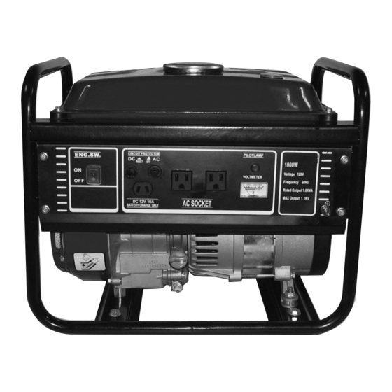
Page 10: Generator Control Illustrations
Generator control illustrations fuel on/off circuit ac outlets pilot lamp air filter cover (67) transparent Meter (1a) switch (52a) protectors (54a) (56a) to show controls underneath. dc (59a) ac (53a) choke oil drain fuel Valves recoil start battery charging dipstick Voltmeter Grounding control (80) -
Page 11: To Start The Engine
to start the engine: Make sure the electrical tools/equipment that will be used are not plugged in to the Generator. Turn on the Fuel Valves (9a, 81). Turn the Valve (9a) under the fuel tank to the vertical ON position and swing the Valve (81) on the carburetor behind the Air Filter right to the ON position. -
Page 12: To Charge 12 V Lead-Acid Type Batteries
to charge 12 V lead-acid type batteries: note: lead-acid batteries can be hazardous. Carefully follow all instructions, safety precautions, and charging procedures as included with the battery you will recharge. batteries contain corrosive acid that can cause blindness or severe injury; always wear splash-resistant ansi-approved safety goggles and work gloves when handling batteries. -
Page 13: Inspection, Maintenance, And Cleaning
inspection, Maintenance, and cleaninG (see maintenance chart on next page.) warninG! Make sure the Power Switch of the generator is in its “OFF” posi- tion, that the engine has cooled, and that all loads are unplugged from the electrical outlets before performing any inspection, maintenance, or cleaning procedures. before eacH use, inspect the general condition of the generator. -
Page 14: Troubleshooting
Maintenance cHart refer to a small engine service manual for procedures not explained in this manual. if you are uncertain about your ability to successfully and safely perform any procedure below, service should be performed by a qualified mechanic. before/ every 3 every 6 Monthly or... -
Page 15: Parts List - Engine
parts list - enGine part description q’ty part description q’ty Crankcase Gasket, cylinder head Valve chamber clapboard sub-assy Cylinder cover Stud M5 × 118 Spark plug Stud M6 × 52 Bolt M6 × 35 Oil seal (17×30×6), crankshaft Gasket, intake port Cover, oil filter Carburetor assy. -
Page 16: Assembly Diagram - Engine
asseMbly diaGraM - enGine for technical questions, please call 1-800-444-3353. SKU 94678 Page 16... -
Page 17: Parts List A - Generator
parts list a - Generator part description q’ty part description q’ty Fuel Meter Gasket Fuel Tank Cap Spring Gasket Fuel Tank Filter Bolt M8 x 170 Flange Bolt M6 x 20 Magneto Cover Gasket Gasket Screw Gasket Spring Gasket Anti-vibration Gasket Bolt M5 x 8 Fuel Tank Lock Nut M8... -
Page 18: Assembly Diagram A - Generator
asseMbly diaGraM a - Generator record product’s serial number Here: note: If product has no serial number, record month and year of purchase instead. note: Some parts are listed and shown for illustration purposes only, and are not available individually as replacement parts. for technical questions, please call 1-800-444-3353. -
Page 19: Emission Control System Warranty
eMission control Harbor freight tools emission control defects warranty systeM warranty provisions california and united states length of coverage emission control defects HFT warrants to a first retail purchaser and each subsequent purchaser that the engine is free from defects in materials warranty statement and workmanship that cause the failure of warranted parts The California Air Resources Board (herein CARB), the United... -
Page 20: Warranty
warranted parts catalyst system (if so equipped) Exhaust pipe stud. fuel Metering system Muffler. Carburetor and its internal parts. iii) Catalytic converter (if so equipped). Fuel pump (if so equipped). Miscellaneous items used in above systems iii) Cold start enrichment system. Vacuum, temperature and time sensitive valves and air induction system switches.
Need help?
Do you have a question about the 94678 and is the answer not in the manual?
Questions and answers