Table of Contents
Advertisement
Quick Links
Advertisement
Table of Contents

Subscribe to Our Youtube Channel
Related Manuals for Monitor Audio GSW12


Summary of Contents for Monitor Audio GSW12
- Page 1 GSW12 User Manual...
-
Page 3: Table Of Contents
Contents Important Safety Instructions Recycling & RoHS Declaration of Conformity Unpacking Foot/Spike Fixing Introduction GSW12 Features Amp & Control Panel Remote Control Functions Positioning Set Up 9-10 Specification Trouble Shooting Guarantee and Service Claims under this guarantee Data Protection EC Declaration of Conformity Owner Information... -
Page 4: Important Safety Instructions
Important Safety Instructions Read these instructions. All the safety and operating instructions should be read before this product is operated. Keep these instructions. The safety and operating instructions should be retained for future reference. Heed all warnings. All warnings on the appliance and in the operating instructions should be adhered to. Follow all instructions. All operating and use instructions should be followed. Do not use this apparatus with water. The appliance should not be used near water or moisture. For example; in a wet basement or near a swimming pool. Clean only with a dry cloth. Great care and attention has gone into the materials chosen to produce the Gold Signature loudspeakers. A gentle wipe with a dry, clean cloth is all that is required to remove any dust. Treat them as you would a fine piece of furniture because that is how they have been designed. -
Page 5: Recycling & Rohs Declaration Of Conformity
WARNING! • THE MAINS PLUG IS USED AS A DISCONNECT DEVICE, THE DISCONNECT DEVICE SHALL REMAIN READILY OPERABLE. • TO PREVENT FIRE OR SHOCK HAZARD, DO NOT USE THIS PLUG WITH AN EXTENSION CORD, RECEPTACLE OR OTHER OUTLET UNLESS THE BLADES CAN BE FULLY INSERTED TO PREVENT BLADE EXPOSURE • TO PREVENT FIRE OR SHOCK HAZARD, DO NOT EXPOSE THIS APPLIANCE TO RAIN OR MOISTURE • TO PREVENT ELECTRIC SHOCK, MATCH WIDE BLADE PLUG TO WIDE SLOT FULLY INSERT. This lightening flash with an arrow head symbol, within an equilateral triangle, is intended to alert the user to the presence of un-insulated “dangerous voltage” within the products enclosure that may be of sufficient magnitude to constitute a risk of electric shock to the persons. Warning: To reduce the risk of electric shock, do not remove cover (or back). No user-serviceable parts inside. Refer servicing to qualified service personnel. This exclamation point within an equilateral triangle is intended to alert the user to presence of important maintenance (servicing) instructions in the literature accompanying the appliance. This is a “Class II”, “double insulated apparatus”. This apparatus must NOT have a safety connection to Earth. Re-cycling Correct Disposal of Waste Electrical and Electronic Equipment (WEEE) by User in Private Households in the EU This symbol on the product or accessories indicates that they must not be disposed... -
Page 6: Unpacking
Unpacking Care must be taken at all times when handling the GSW12 due to the extreme weight of the product. We recommend a two-person lift wherever appropriate. The feet/spike assemblies and mains power cord/s are contained within the packaging and should be removed. Please select the power cord appropriate to your Country/location. Mains voltage selection for 100-120 Vac or 220-240 Vac operation is electronically auto selected. To remove the GSW12 from its carton, place some protective material on the floor and having removed any items of packing from the top of the pack carefully invert the carton. (Also see icons on the carton). Gradually pull the carton upwards to expose the subwoofer, which will be presented with its base uppermost. Remove fixing tape from the bag and expose the base of the cabinet to allow fitting of the spiked feet into the M10 threaded inserts as described below. Spiked Foot Fixing For Carpeted Floors The spiked foot assembly incorporates a spike for use on carpeted floors and also, a soft polymer pad (for use on wooden or tiled floors). Please ensure there are no hidden wires under the carpet, or trailing mains leads that could be damaged by the spikes. The foot comes fully assembled for use on carpeted floors. All that is required is fixing into the cabinet. This is achieved by simply screwing Locking Nut the feet fully into the 4-threaded inserts in the underside of the cabinet. -
Page 7: Introduction
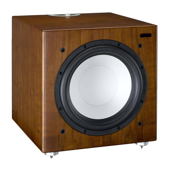
Introduction Thank you for your purchase of Monitor Audio GSW12 subwoofer, which has been designed and constructed using quality systems and materials to provide years of enjoyment, reliability and pride of ownership. This product, as with all the Gold Signature range, is hand crafted from top to bottom using traditional woodworking skills for our sumptuous cabinets, married with the state of the art technology of our renowned drive units. Music is and should be a natural enhancement of life. It stimulates the imagination, changes your mood, helps you relax, and provides endless hours of entertainment. Please read through this manual to familiarize yourself with any safety advice and how best to set up your subwoofer to achieve the very best listening experience. Please retain this manual for future reference. GSW12 Features • Compact design with forward firing 12” long-throw woofer. • Class D amplifier section with advanced SMPSU (Switch mode) power supply unit. • Dynamic power limiter. DSP (Digital Sound Processing) control of the power amplifier monitors available power and limits certain frequencies dependant on available power reserve. • Sealed cabinet for ultimate bass control and ease of installation. • Main features and settings adjustable by remote control. • Full DSP Control with all functions controlled in the digital domain, providing more advanced control of complex filter characteristics than conventional analogue circuitry. -
Page 8: Amp & Control Panel
Amp and Control Panel Monitor Audio 2007 GSW12 Rev 1... - Page 9 1. RCA Line Level Inputs (Stereo Left & Right) For connection to a 2 channel/ stereo amplifier system. Connection should be provided by a pair of high-quality signal cables from the pre-out section of an amplifier. Note: - cable lengths should not exceed 10 metres to avoid interference from other electrical appliances. 2. RCA Line Level Outputs (Stereo Left & Right) RCA line level outputs are provided in order to use other sub-woofers in conjunction with the GSW12 by ‘daisy chain’ type connection. The outputs are link out only connections and do not provide any form of filtering. 3. LFE Input (RCA Type) This input is to be used when connecting the GSW12 to an AV amplifier/receiver. When using the LFE input, the crossover function in the menu/set-up is not used. This is due to the crossover function being controlled by the AV amplifier/ processor to which it is connected. Please refer to the crossover table on page 10 for further advice on which setting to use. Input between LFE and Stereo input (Inp) can be switched using the ‘LFE’ button on the remote control unit.
-
Page 10: Remote Control Functions
Remote Control NOTE: - The remote control should be directed towards the IR lens located on the front of the GSW12 cabinet. For distance and angle limits please refer to the Set Up Guide (page 2). 1. Mute Toggle between mute and normal operation. Mute can only be accessed by using the remote control. 2. Power/ Standby Toggle between standby on/off. Standby can only be operated by the remote control unit. This function will not be operable when using the +12v trigger. 3. LFE Toggle between LFE and Stereo input. The input mode can only be accessed by using the remote control. 4. Night Mode Toggle between night mode on/off. Night mode can be accessed by the remote control and by the main control panel menu. -
Page 11: Positioning
Positioning The GSW12 should now be sited in the most suitable position, preferably not directly in the corner of a room as this may cause excessive bass boom. Once a desirable position is achieved it is important to check if the cables are long enough to reach comfortably without being under tension. Leave the GSW12 unplugged until you are happy with it’s location. Never connect or disconnect any of the input connections with the GSW12 switched on. Optimal control settings will depend entirely on your system configuration. For initial trials set the controls as follows: Set Up Once in position and cables have been routed; connect them to the GSW12. Mains power cable should be connected last. Do not play any music at this stage. NOTE: The entire set up procedure can be done via the control panel or remote control handset. Using an A/V Processor/Receiver Connect a single interconnect cable from an A/V processor/receiver to the connection marked LFE input. LFE must be displayed on the control panel display. If ‘Inp’ (indicating stereo input) is displayed, the LFE button on the remote control can be pressed to select LFE. LFE should then be indicated on the display. - Page 12 Crossover setting (Stereo left & right input only) The crossover control should be set in accordance with the size or bass output of the main/satellite speakers. The crossover control can be adjusted in steps of 40Hz, 50Hz, 63Hz, 80Hz, 100Hz, 125Hz and 160Hz. The crossover slope characteristic can also be adjusted from 0 to 54dB/Octave in steps of 6dB. Refer to the chart below as a guide to setting the crossover frequency control to the optimum position. Much will depend on the correct low frequency response of the main speakers and their position in your room. Experimentation is advisable. Type of Main Speaker Monitor Audio Product Crossover Control Setting Large floor-standing speaker GS20/60; RS6/8; BR6 40-60Hz Small floor-standing speaker RS5; BR5; R270 60-70Hz Large stand-mount/bookshelf speaker GS10 50-80Hz Small stand-mount/bookshelf speaker RS1; BR1/2; R225/250 60-90Hz Small satellite speaker R45/90/180 80-160Hz Sub-Sonic filter An adjustable sub-sonic filter is provided to limit the reproduction of infra-sonic frequencies being produced below a useable frequency point. Frequency settings are at 16, 20, 25 and 31Hz with a variable slope characteristic from 0 to 54dB/Octave in...
-
Page 13: Specification
Specification Amplifier Output 600 Watts (RMS) 1200 Watts (Peak) Crossover (Low Pass) 40Hz - 160Hz Variable slope characteristic from 6 – 54dB/Octave Sub-Sonic Filter (High Pass 16, 25 & 31Hz Variable slope characteristic from 6 – 54dB/Octave 4 x Preset 1 x User Set Equalisation Graphic 10 Band Equaliser. ± 6dB in 0.5dB steps Digital Volume Level -80 – 0dB in 1dB Increments Auto Sensing Input Line Level >5mV (RMS) Requirements 5 – 25 minutes, user adjustable. Cabinet Specification Sealed Cabinet with 25mm M.D.F construction with critical internal bracing. Sealed amplifier compartment. Amplifier Classification Class- D amplifier, with SMPSU (switch mode power supply) and DSP control Driver Compliment 1 x 12” C-CAM® sub-woofer driver featuring triple suspension and 4” long throw voice coil Dimensions Millimetres - 390 x 390 x 420 (H x W x D) Inches 15 3/8 x 15 3/8 x 16 9/16 All dimensions excluding grille and feet Weight (unpacked) 28 Kg (61.5lbs) Mains Input Voltage:- 100 -120Vac, 220 - 240 Vac (Automatically selected) Fuse Type For countries with 220 – 240Vac supply use: 4A/250V 20MM UL/VDE For countries with 100 – 120Vac supply use: 8A/250V 20MM UL/VDE Trigger Input 3.5mm Jack input, +12Vdc = On State Code System for All in One... -
Page 14: Trouble Shooting
• Have you got the 12v trigger connected? If so, the GSW12 will not power up using the remote with this connected. It will only turn on when the 12v trigger source is powered up. • Has it got a signal going to it? If so, and the signal is turned on, try adjusting the volume level of the source. If it still does not turn on/ power up, please contact your local dealer/ distributor or Monitor Audio immediately. No sound from GSW12 • Check the correct input is selected to suit your needs. • Is the LED on the back red or green? If it is red, then the unit hasn’t actually turned on. See above comments. If it is green, then your unit is powered up and turned on. Check further suggestions below. -
Page 15: Guarantee And Service
Guarantee and Service Valid upon completion of the incorporated warranty card and its return within 30 days of purchase. This equipment has been fully tested prior to dispatch from the factory. Both the craftsmanship and the performance of this product is guaranteed against manufacturing defects for the period of one year from the date of purchase (see conditions below), provided that the product was supplied by an authorised Monitor Audio retailer under the consumer sale agreement. (The words ‘consumer sale’ shall be construed in accordance with section 15 of the supply of goods act 1973). Monitor Audio accepts no responsibility for defects arising from accident, misuse, abuse, wear and tear, modification or operation outside of that specified within this instruction manual. Neither will responsibility be accepted for damage or loss occurring during transit to or from the parties claiming under this guarantee. This guarantee covers both labour and parts. The liability of Monitor Audio is limited to the cost of repair or replacement of the defective parts (at the discretion of Monitor Audio) and under no circumstances extends to consequential losses or damage. Claims under this Guarantee The equipment should be returned in its original packaging to the original supplier where possible, or to any other authorised Monitor Audio dealer. If it is not possible to return the equipment by hand, then it should be sent carriage prepaid via a reputable carrier. If the original packing is not available replacement packaging can be purchased from Monitor Audio. If you have any difficulties complying with these requirements please contact us at the following address: Customer Service Tel: 44 (0) 1268 740580 Monitor Audio Ltd. -
Page 16: Ec Declaration Of Conformity
EC Declaration of Conformity EC Declaration of Conformity We, Monitor Audio Ltd. Unit 2,24 Brook Road Rayleigh Essex SS6 7XL England Declare in own responsibility, that the GSW12 product described in this manual is in compliance with Technical Standards/Council Directives: (LVD) 2006/95/EC Low Voltage Directive EN60065: 2002+A1: 2006 Safety requirements for mains operated electronic and related apparatus for household and similar use. -
Page 17: Owner Information
Owner Information Product Details Model GSW12 Product Serial No:................................Date of Purchase:................................Dealer Details Dealer Name:..................................Address:.................................... Town, Post code, Country:..............................e-mail address:.................................. Settings/Notes: Left & Right Stereo Input LFE Input Crossover (Set on AV amplifier/processor):....Crossover (Set on AV amplifier/processor):....................................Sub-Sonic Filter:............Sub-Sonic Filter:............................................EQ:................EQ:................ - Page 18 ® Monitor Audio Ltd. Unit 2, 24 Brook Road Rayleigh, Essex SS6 7XL England Tel: 01268 740580 Fax: 01268 740589 Email: info@monitoraudio.co.uk www.monitoraudio.co.uk Designed in the United Kingdom Version 1...
Need help?
Do you have a question about the GSW12 and is the answer not in the manual?
Questions and answers