Table of Contents
Advertisement
Quick Links
Contents
Part 2: Installation Instructions Cl. 745-22; -23; -24
1.
Scope of Delivery . . . . . . . . . . . . . . . . . . . . . . . . . . . . . . . . . . . . . . . . . . .
2.
2.1
Removing the Transport Fastening . . . . . . . . . . . . . . . . . . . . . . . . . . . . . . . . . .
2.2
Transport . . . . . . . . . . . . . . . . . . . . . . . . . . . . . . . . . . . . . . . . . . . . . . . .
2.3
Setting the Work Height . . . . . . . . . . . . . . . . . . . . . . . . . . . . . . . . . . . . . . . .
2.4
2.5
Filling Oil . . . . . . . . . . . . . . . . . . . . . . . . . . . . . . . . . . . . . . . . . . . . . . . .
3.
3.1
Pedal . . . . . . . . . . . . . . . . . . . . . . . . . . . . . . . . . . . . . . . . . . . . . . . . . .
3.2
Yarn Stand . . . . . . . . . . . . . . . . . . . . . . . . . . . . . . . . . . . . . . . . . . . . . . .
3.3
Folder . . . . . . . . . . . . . . . . . . . . . . . . . . . . . . . . . . . . . . . . . . . . . . . . . .
3.4
3.5
Throw-over Stacker (Optional Equipment) . . . . . . . . . . . . . . . . . . . . . . . . . . . . . .
4.
4.1
Connecting the Microcontrol Control Unit . . . . . . . . . . . . . . . . . . . . . . . . . . . . . .
4.2
Checking the Nominal Voltage . . . . . . . . . . . . . . . . . . . . . . . . . . . . . . . . . . . .
4.3
Setting the Motor Protection Switch . . . . . . . . . . . . . . . . . . . . . . . . . . . . . . . . .
4.4
Checking the Direction of Turn of the Motor . . . . . . . . . . . . . . . . . . . . . . . . . . . . .
4.5
Checking the Positioning . . . . . . . . . . . . . . . . . . . . . . . . . . . . . . . . . . . . . . .
5.
Pneumatic Connection . . . . . . . . . . . . . . . . . . . . . . . . . . . . . . . . . . . . . . . .
. . . . . . . . . . . . . . . . . . . . . . . . . . . . . . . . . . . . .
Page:
Home
3
3
4
4
5
5
6
7
7
8
9
10
11
11
12
13
14
Advertisement
Table of Contents

Related Manuals for Duerkopp Adler 745-22

Summary of Contents for Duerkopp Adler 745-22
-
Page 1: Table Of Contents
Contents Page: Home Part 2: Installation Instructions Cl. 745-22; -23; -24 Scope of Delivery ......... . . Installing the Sewing Unit Removing the Transport Fastening . -
Page 3: Scope Of Delivery
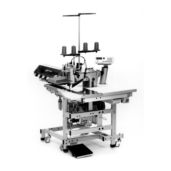
1. Scope of Delivery – Stand with sewing drive – Step motor for the material transport – Two needle-double saddle stitch machine Class 935-246-00 745-22;-23: with parts set 935 745301 for the common switching of the needle bars 745-24: with parts set 935 745310 for the independent switching of the needle bars –... -
Page 4: Transport
2.2 Transport The stand of the sewing unit is equipped with four castors for in-house transport. ATTENTION ! Before commissioning the sewing unit place the sound absorbers 2 (in the accessories pack) on the four feet of the stand. Turn in the castors until the stand is stable. –... -
Page 5: Checking The V-Belt Tension
2.4 Checking the V-belt Tension After transport check the V-belt tension set at the factory. With correct tension the V-belts 5 (from the sewing drive to the intermediate gear) and 1 (from the intermediate gear to the machine head) can still be pressed in approx. 10 mm at the center with finger pressure. -
Page 6: Attaching The Machine Parts Removed For Shipment
3. Attaching the Machine Parts Removed for Shipment 3.1 Pedal Sewing units for jacket fabrication are equipped with only one pedal. Those equipped for trouser fabrication have a left and a right pedal. The pedal 3 is to be attached at the lower cross spar 4: –... -
Page 7: Yarn Stand
3.2 Yarn Stand – Place the yarn stand 1 in the drilled hole 2 of the housing and attach with nuts and washers. – Mount and align the yarn plates and take-off arms as shown in the illustration. 3.3 Folder –... -
Page 8: Table Extensions (Optional Equipment)
3.4 Table Extensions (Optional Equipment) Table extension for trouser seat pieces – Fasten the table extension 2 with the screws 3 and the bracket to be found behind spar 1. – Loosen the screws on the table top slightly. By sliding the table extension 2 establish a clearance to the table. This clearance is necessary for the free movement of the positioned pocket bag. -
Page 9: Throw-Over Stacker (Optional Equipment)
3.5 Throw-over Stacker (Optional Equipment) The throw-over stacker (Order no. Z112 427514) is attached to the frame of the sewing unit with holder pipe 1. At delivery of the sewing unit the holder pipe 1 is already premounted on the frame brace 3. If the throw-over stacker is delivered separately packed, the holder pipe 1 must first be attached to the frame brace 3 of the sewing unit. -
Page 10: Electrical Connection
4. Electrical Connection ATTENTION ! All work on the electrical components of the sewing unit may only be conducted by electricians or appropriately instructed persons. The mains plug must be pulled. 4.1 Attaching the Microcontrol Control Unit The Microcontrol control unit is fastened onto plate 1 with the set screws 2. -
Page 11: Checking The Nominal Voltage
4.2 Checking the Nominal Voltage The nominal voltage given on the rating plate of the sewing drive and the mains voltage must agree! For conversion to a different mains voltage the appropriate voltage kit must be mounted. The voltage kit consists of: V-belt pulley, V-belt, protection switch insert Nominal voltage: Order no.:... -
Page 12: Checking The Direction Of Turn Of The Motor
4.4 Checking the Direction of Turn of the Motor ATTENTION ! Before commissioning of the sewing unit it is essential that the direction of turn of the motor be checked. Turning the machine on with an incorrect direction of turn can lead to damage to the sewing unit. -
Page 13: Checking The Positioning
4.5 Checking the Positioning Before commissioning check the positioning set at the factory. After turning on the main switch the sewing unit must position in the needle high position (Position 2). Checking the positioning – Turn the main switch off. –... -
Page 14: Pneumatic Connection
5. Pneumatic Connection The sewing unit must be supplied with water-free compressed air for the operation of the pneumatic components. ATTENTION ! For a flawless functioning of the pneumatic control procedures the compressed air supply must be laid out as follows: Even at the instant of greatest air consumption the minimum operating pressure may not fall below 5 bar.
Need help?
Do you have a question about the 745-22 and is the answer not in the manual?
Questions and answers