Table of Contents
Advertisement
Quick Links
Postfach 17 03 51, D-33703 Bielefeld • Potsdamer Straße 190, D-33719 Bielefeld
Telefon +49 (0) 521 / 9 25-00
Ausgabe / Edition:
Änderungsindex
03/2009
Rev. index: 00.0
Spezialnähmaschine
•
Telefax +49 (0) 521 / 9 25 24 35 • www.duerkopp-adler.com
Printed in Federal Republic of Germany
869
Betriebsanleitung
Instruction manual
Teile-Nr./Part.-No.:
0791 869741
D
GB
Advertisement
Table of Contents

Related Manuals for Duerkopp Adler 869


Summary of Contents for Duerkopp Adler 869
-
Page 1: Instruction Manual
Spezialnähmaschine Betriebsanleitung Instruction manual Postfach 17 03 51, D-33703 Bielefeld • Potsdamer Straße 190, D-33719 Bielefeld Telefon +49 (0) 521 / 9 25-00 • Telefax +49 (0) 521 / 9 25 24 35 • www.duerkopp-adler.com Ausgabe / Edition: Änderungsindex Teile-Nr./Part.-No.: 03/2009 Rev. - Page 2 Alle Rechte vorbehalten. Eigentum der Dürkopp Adler AG und urheberrechtlich geschützt. Jede, auch auszugsweise Wiederverwendung dieser Inhalte ist ohne vorheriges schriftliches Einverständnis der Dürkopp Adler AG verboten. All rights reserved. Property of Dürkopp Adler AG and copyrighted. Reproduction or publication of the content in any manner, even in extracts, without prior written permission of Dürkopp Adler AG, is prohibited.
- Page 3 Foreword This instruction manual is intended to help the user to become familiar with the machine and take advantage of its application possibilities in accordance with the recommendations. The instruction manual contains important information on how to operate the machine securely, properly and economically. Observation of the instructions eliminates danger, reduces costs for repair and down-times, and increases the reliability and life of the machine.
-
Page 4: General Safety Instructions
General safety instructions The non-observance of the following safety instructions can cause bodily injuries or damages to the machine. 1. The machine must only be commissioned in full knowledge of the instruction book and operated by persons with appropriate training. 2. -
Page 5: Table Of Contents
Contents Page: Preface and General Safety Instructions Part 1: Operating Instructions Class 869 (Edition 03/2009) Product Description ..........Designated Use . - Page 6 Contents Page: Tilting Back the Machine Head ........Folding Down the Table Top with the MG 56-2 Stand .
-
Page 7: Product Description
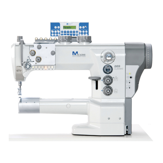
Product Description The DÜRKOPP ADLER 869 is a single-needle double lockstitch free-arm sewing machine with a lower feed, a needle feed and an alternating foot-upper feed. Depending on the subclass it comes as single or double needle machine, with or without electropneumatic driven thread trimmer. ·... -
Page 8: Subclasses
This special sewing machine may be set up and operated only in dry, well-maintained premises. If the sewing machine is used in premises which are not dry and well-maintained it may be necessary to take further precautions which should be agreed in advance (see EN 60204-31:1999). -
Page 9: Optional Equipment
Optional Equipment The following optional equipment is available for the 869. Order No. Optional equipment Subclasses 9780 000108 WE-8 maintenance unit for pneumatic optional equipment 0797 003031 Pneumatic connection package For connection of stand with maintenance unit. 0867 490010 Operating panel angle bracket 9822 510001 Halogen sewing light for sewing machine head 9880 867100... -
Page 10: Technical Data
Further available documents concerning the class 869: 0791 869801 Parts List 0791 869641 Service Instructions Technical data Noise: Workplace-related emission value in accordance with DIN 45635-48-A-1-KL2 869-180020 LC = _dB (A) Stitch length: _ mm Sewing-foot stroke: __ mm Speed: ___ min Material: 869-180122 LC = _dB (A) -
Page 11: Technical Data Subclasses
5.1 Technical data subclasses Subclass Type of stitch Lockstitch 301 Hook type vertical, large Number of needles Needle system 134-35 Needle size max. (depending on E-No.) [Nm] Max. thread thickness Needle thread [Nm] 80/3 - 10/3 Hook thread [Nm] 100/3 - 10/3 Stitch length [mm] Forwards... - Page 12 Threading scheme single-needle machine Threading scheme double-needle machine...
-
Page 13: Operation
Operation 6.1 Threading the needle thread Caution: Risk of injury! Turn off the main switch! The needle thread may only be threaded with the sewing machine switched off. Threading in the needle thread with single-needle machines – Put the thread reel on the thread stand and lead the needle thread through the unwinder arm. -
Page 14: Adjusting The Needle-Thread Tension
6.2 Adjusting the needle-thread tension Pre-tension When the main tensioner 2 and supplementary tensioner 3 are open, the needle thread must be under slight residual tension. This residual tension is produced by the pre-tensioner 1. The pre-tensioner 1 simultaneously affects the length of the end of the severed needle thread (the starting thread for the next seam). -
Page 15: Function Of The Main Thread Tension And The Supplementary Thread Tension In Relation To The Sewing Foot Lifting For Subclass 869
Fig. A Correct thread interlacing in the center of the material Fig. B Needle-thread tension too weak Hook-thread tension too strong Fig. C Needle-thread tension too strong Hook-thread tension too weak 6.2.1 Function of the main thread tension and the supplementary thread tension in relation to the sewing foot lifting for subclass 869- ... -
Page 16: Function Of Supplementary Thread Tension In Relation To The Sewing Foot Lifting And The Speedomat For Subclass 869
6.2.2 Function of supplementary thread tension in relation to the sewing foot lifting and the Speedomat for subclass 869- ... The thread supplementary tension can, at any time, be switched on or off by actuating key 1 (see chapter 6.14) of the key pad. The parameter F-255 must be set on “7"... -
Page 17: Turning The Supplementary Thread Tension On And Off For Subclasses 869-180020, 869-280020, 869-180122 And 869-280122
6.4 Turning the supplementary thread tension on and off for subclasses 869-180020, 869-280020, 869-180122 and 869-280122 The supplementary tension is being switched on and off with lever 1. Switching on – Push the handle 2 of lever 1 to the left. Switching off –... -
Page 18: Adjusting The Thread Regulator
6.5 Adjusting the thread regulator Caution: Risk of injury! Turn off the main switch. The thread regulator may only be adjusted with the sewing machine switched off. The thread regulator 1 controls the quantity of needle thread required for stitch formation. The thread regulator must be precisely adjusted for an optimum result. -
Page 19: Winding On The Hook Thread
6.6 Winding on the hook thread – Put the thread reel on the thread stand and lead the needle thread through the unwinder arm. – Pull the thread through the thread guide 3, the tensioner 5 and the thread guide 3. –... -
Page 20: Changing The Hook-Thread Bobbin
6.7 Changing the hook-thread bobbin Caution: Risk of injury! Turn off the main switch. The hook-thread bobbin may only be changed with the machine switched off. Remove the empty bobbin – Slide the cover 1 sideways, raise up the flap 7 and remove the empty bobbin 2. -
Page 21: Setting The Hook Thread Tension
6.8 Setting the hook thread tension Caution: Risk of injury! Turn the main switch off! The hook thread tension may only be adjusted with the sewing machine switched off. Setting the tension spring 2 – Set the tension spring 2 by turning the adjustment screw 1. Increase the hook thread tension = Turn screw 1 clockwise Decrease the hook thread tension =... -
Page 22: Inserting And Changing The Needle With Single-Needle Machines
6.9 Inserting and changing the needle with single-needle machines Caution: Risk of injury! Turn off the main switch. The needle may only be changed with the sewing machine switched off. – Turn the hand wheel, until the needle bar 1 has reached its highest position. -
Page 23: Inserting And Changing The Needle With Double-Needle Machines
6.10 Inserting and changing the needle with double-needle machines Caution: Risk of injury! Turn the main switch off! The needle may only be changed with the sewing machine switched off. – Turn the hand wheel, until the needle bar 1 has reached its highest position. -
Page 24: Lifting The Sewing Foot
6.11 Lifting the sewing foot Subclass 869-180020, 869-280020 The sewing feet can be lifted mechanically by actuating the knee lever 1. Subclasses 869-180112, 869-180322, 869-280122, 869-280322 The sewing feet can be lifted electro-pneumatically by actuating the pedale 2 or the knee lever 1. Mechanical sewing foot lifting (Knee lever) –... -
Page 25: Locking The Sewing Feet In Lifted Position
6.12 Locking the sewing feet in lifted position – Push the lever 1 downwards. The sewing feet are locked in lifted position. – Push the lever 1 upwards. The sewing feet are released. – Lift the sewing feet pneumatically or by pushing the knee lever. The lever 1 then moves back into its initial position. -
Page 26: Sewing-Foot Stroke
6.14 Sewing-foot stroke The special sewing machine 869 has, depending on the subclass, as standard equipment two setting wheels for the sewing foot stroke. With the left setting wheel 2 the standard sewing foot stroke from 1 to 9 mm is selected. - Page 27 Operation mode of the quick stroke adjustment The activation period of the maximum sewing foot stroke depends on the set operation mode. It is possible to choose between three operation modes. The individual operation modes are determined by the setting of the parameters F-138 and F-184 at the control panel (see enclosed instructions of the motor manufacturer).
-
Page 28: Setting The Stitch Length
6.15 Setting the stitch length The special sewing machine 869 has, depending on the subclass, as standard equipment two setting wheels. Thus, two different stitch lengths can be sewn, that are activated by actuating the key 4 (see chapter 6.15). The two stitch lengths are set with the setting wheels 1 and 2 on the machine arm. -
Page 29: Key Pad On The Machine Arm
6.16 Key pad on the machine arm Function Supplementary tread tension Button is back-lit: the supplementary thread tension is activated. Button is not back-lit: the supplementary thread tension is not activated. 2nd stitch length Button is back-lit: long stitch length (upper setting wheel) is activated Button is not back-lit: small stitch length (lower setting wheel) is activated... -
Page 30: Sewing
Function LED display “Power On” The function of key 7 can be selected with the screw 6 under the keys. – Selecting a function. Example: 6 = Manually sewing backward. – Turn in the screw 6 under the key 5 and turn it 90° to the right (the slot stands vertically). -
Page 31: Sewing With Machines Using The Efka Dc1550/Da321G Positioning Drive
7.2 Sewing with machines using the Efka DC1550/DA321G positioning drive The control unit DA321G contains all required operational interfaces for switching functions and setting parameters. It is possible to operate without an operating panel, but the seam programming cannot be carried out. The V810 and V820 operating panels can also be connected to the control unit. - Page 32 Sewing process Operation / Explanation Prior to sewing Starting position - Pedal is in the resting position. The sewing machine is at rest. The needle is up. The sewing feet are down. Position material at seam start - Move pedal back halfway. Raise the sewing feet.
- Page 33 Sewing over a cross seam. The maximum sewing-foot stroke is activated. (max. sewing foot stroke) The speed is limited to 1600 min-1. Operating modes for maximum sewing-foot stroke: - Press the knee switch briefly for activating the maximum sewing-foot stroke. - Press the knee switch briefly again for deactivating the maximum sewing-foot stroke.
-
Page 34: Tilting Back The Machine Head
Tilting Back the Machine Head Caution Crushing Hazard! Do not reach between the base and the machine arm while tilting back the machine head. Tilting back the machine head – Pull lever 1 upwards. The locking mechanism is then released. –... -
Page 35: Folding Down The Table Top With The Mg 56-2 Stand
Folding Down the Table Top with the MG 56-2 Stand Caution: Risk of injury! Always hold the table top with both hands when pulling it out. – Loosen the table top latch 1 located under the table top. – Pull out the table top 2 to the left and fold out. –... -
Page 36: Maintenance
10. Maintenance 10.1 Cleaning and Checking Caution: Risk of injury! Turn the main switch off! Maintenance may only be carried out with the machine switched off! Maintenance work must be carried out no less frequently than at the intervals given in the tables (see “operating hours” column). Maintenance intervals may need to be shorter when processing heavy-shedding materials. - Page 37 Maintenance work Explanation Operating to be carried out hours Sewing motor Remove lint and pieces of thread from Clean fan grille 2. air-intake openings. (e.g. with an air blow gun) It must be possible to depress the V-belt by Check condition and about 10 mm by pressing it with a finger at tension of V-belt 1 its mid-point.
-
Page 38: Oil Lubrication
10.2 Oil Lubrication Caution: Risk of injury! Oil can cause skin eruptions. Avoid protracted contact with the skin. In the event of contact, thoroughly wash the affected area. ATTENTION! The handling and disposal of mineral oils is subject to legal regulation. Deliver used oil to an authorised collection point.
Need help?
Do you have a question about the 869 and is the answer not in the manual?
Questions and answers