Table of Contents
Advertisement
Quick Links
Semi automatic arc welding machine
This manual applies to
Part No.
Code Desc
KA1392
1447
CV320-I
KA1392-1 1473
CV320-I
KA1392
1509
CV320-I
KA1392-1 1510
CV320-I
KA1392
1535
CV320-I
Lincoln Electric welders are designed and built with safety in mind. However, your overall safety can be increased by
proper installation . . . and thoughtful operation on your part. Read and observe the general safety precautions on
page 2 and follow specific installation and operating instructions included in this manual.
OPERATING MANUAL
CV320-I
Volts
415
380
415
380
415
SAFETY DEPENDS ON YOU
Most importantly, think before you act and be careful.
THE LINCOLN ELECTRIC COMPANY
(AUSTRALIA) PTY. LTD.
THE LINCOLN ELECTRIC CO. U.S.A.
Associated Subsidiaries in Australasia, Europe, North and South America.
THE WORLD'S LEADER IN WELDING AND CUTTING PRODUCTS
ACN 000 040 308
A.C.N. 000 040 308
SYDNEY. AUSTRALIA
A Subsidiary of
IMA 574B
Advertisement
Table of Contents

Related Manuals for Lincoln Electric CV320-I


Summary of Contents for Lincoln Electric CV320-I
- Page 1 SAFETY DEPENDS ON YOU Lincoln Electric welders are designed and built with safety in mind. However, your overall safety can be increased by proper installation . . . and thoughtful operation on your part. Read and observe the general safety precautions on page 2 and follow specific installation and operating instructions included in this manual.
-
Page 2: Electric Shock Can Kill
PROTECT YOURSELF AND OTHERS FROM POSSIBLE SERIOUS INJURY OR DEATH. READ AND UNDERSTAND BOTH THE SPECIFIC INFORMATION GIVEN IN THE OPERATING MANUAL FOR THE WELDER AND/OR OTHER EQUIPMENT TO BE USED AS WELL AS THE FOLLOWING GENERAL INFORMATION. ARC WELDING SAFETY PRECAUTIONS ARC RAYS can burn ELECTRIC SHOCK can kill 1. - Page 3 FOR ENGINE powered CYLINDER may explode if equipment damaged 5. a. Use only compressed gas cylinders containing the 7. a.Turn the engine off before troubleshooting and correct shielding gas for the process used and maintenance work unless the maintenance properly operating regulators, designed for the gas work requires it to be running.
- Page 4 WELDING, EMF AND PACEMAKERS All welders should follow safe practices that minimize their Welders with Pacemakers exposure to electric and magnetic fields (EMF). There is no question that the fields in arc welding can interfere For welders wearing implanted pacemakers, safe welding with a pacemakers function.
-
Page 5: Assessment Of Area
British Standard EN 50199). contact is maintained between the conduit and the welding power • for using with other Lincoln Electric/LiquidArc equipment. source enclosure. • designed for industrial and professional use. -
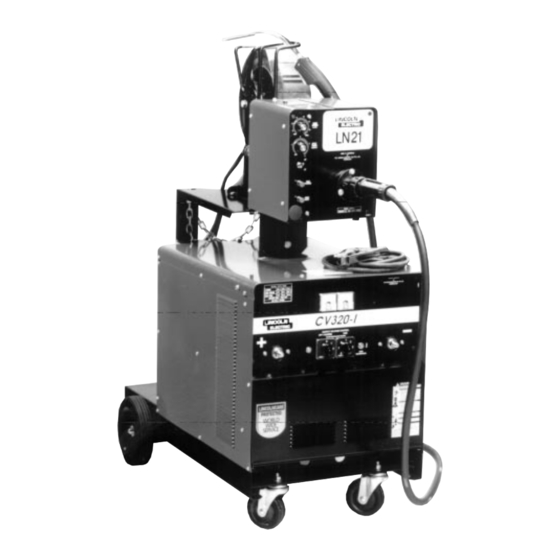
Page 6: Product Description
PRODUCT DESCRIPTION The CV320-I is a semi-automatic Constant Voltage DC arc welding power source and wire feeder. It combines a step controlled power source with a separate solid state controlled wire feeder. Excellent arc characteristics are provided for both gas shielded and self shielded welding within its current range. For instructions on operation of the wire feeder refer to the separate instruction manual included. - Page 7 DO NOT ATTACH THE REGULATOR/FLOWMETER IF NOTE: If a gun and cable other than the Magnum FM400 gun are CYLINDER VALVE IS DAMAGED! Inform your gas supplier of this to be used, they must conform to standard European-style condition. connector specifications. See diagram under. Stand to one side away from the outlet and open the cylinder valve for an instant.
-
Page 8: Operating Instructions
OPERATING INSTRUCTIONS Pilot Light WARNING This light illuminates when the input mains power is switched on Volts Control • Do not touch electrically live parts or The output voltage is controlled by two rotary switches. One rotary electrode with skin or wet clothing. switch provides four “coarse”... -
Page 9: Gun And Cable Maintenance
If gas shielding is required, see Section 1.4. Connect the gas General hose. In extremely dusty locations, dirt may clog the air passages and Remember that gas cylinders may explode if damaged, so ensure cause the welder to run hot. Blow dirt out of the welder with low- that all gas cylinders are securely mounted. -
Page 10: Troubleshooting Guide
TROUBLESHOOTING GUIDE WARNING • Have an electrician install and service this equipment. • Turn the input power off at the fuse box before working on equipment. • Do not touch electrically hot parts. ELECTRIC SHOCK can kill Problem Possible Cause What To Do Rough wire feeding or wire Gun cable kinked and/or twisted. - Page 11 TROUBLESHOOTING GUIDE (cont) Problem What To Do Possible Cause No wire feed, although arc Defective wire feed motor or wire drive Measure the voltage between Red motor lead voltage is present. control PC board. (54) and the Green motor lead (53) when the wire inch push button is depressed.
- Page 12 Note: LN-21 Code Nos less than Code No. 1508 use drive roll part No. starting with ‘AM’. For LN-21 Code Nos greater than or equal to Code No. 1508 use drive roll part Nos starting with ‘AS’. DRIVE ROLLS Machine Machine Code 1508 Code 1413...
- Page 13 The Lincoln Electric Company (Australia) Propriety Limited AP-80 A.C.N. 000 040 308 Operative: 2/7/99 Supercedes: 18/6/97 CV320-I PARTS LIST AP-80 Do not use this Parts List for a machine if its code number is not listed. Contact the Service Department for any code numbers not listed.
- Page 14 AP-80-C General Assembly AP-80-C Operative: 2/7/99 Supercedes: 18/6/97 Roof and side panels not shown for clarity. Platform shown this view only. Ref: AG1369 Front panel not shown for clarity. A15-5-96M Page 14 CV320-I IMA 574B...
- Page 15 AP-80-C.1 Operative: 2/7/99 Supercedes: 18/6/97 General Assembly AP-80-C.1 When ordering parts quote AP-80-C-1, Machine Serial & Code Numbers, Part Description and Item Number. Item Part No. Description Qty. 1 2 Item Part No. Description Qty. 1 M6819-4A AT3070-3 Connector Block Loctite #262 1.0mL X X AM3423...
- Page 16 AP-80-D Operative: 2/7/99 Supercedes: 18/6/97 Control Panel AP-80-D Ref: AL2524 (AL21-2-96M) When ordering parts quote AP-80-D, Machine serial & Code numbers, part description and item number. Item Part No. Description Qty. AG1355 Front Panel AL2516 Nameplate T14659-1 Fastener Button (Black) AM3397-1 Voltmeter AM3398-1...
- Page 17 WIRING DIAGRAM CV320-I IMA 574B CV320-I Page 17...
- Page 18 AP-68 Operative: 18/6/97 Supersedes: 26/11/96 LN21 WIRE FEEDER PARTS LIST AP-68 Do not use this Parts List for a machine if its code number is not listed. Contact the Service Department for any code numbers not listed. Numbers in the table below indicate which column to use in each parts list for each individual code number. Sub Assembly Item No.
- Page 19 AP-68-C General Assembly AP-68-C Operative: 18/6/97 Supercedes: 26/11/96 Ref: AG1346A (16.7.97) Item Part Name and Description No. Req. Part Number 1 BASE, FRONT AND REAR PANEL AG1344 BASE, FRONT AND REAR PANEL AM3161 PLASTIC FOOT AT4084-1 BULKHEAD AM3379 SELF TAPPING SCREW AS1733-3Z GROMMET AS3086-9...
- Page 20 General Assembly AP-68-C.1 AP-68-C.1 Operative: 18/6/97 Supercedes: 26/11/96 Note: 4 Wheel Shown. See Fig.1 or Fig.2 for two wheel drive. Note: To upgrade from the AM3391-1 drive plate to AM3391-7 drive plate you will also need to purchase AM3390-2 plus S9225-7. Ref: AG1346B (25.6.97) Item Part Name and Description Part Number...
- Page 21 WIRING DIAGRAM LN21 IMA 574B CV320-I Page 21...
- Page 22 AP-202-G Magnum Fastmate Guns Operative: 10/3/97 Supercedes: AP-202-G Part No. K479-7 Magnum FM400 3.65m long Item Part No. Description Item Part No. Description Gas nozzle, Fixed, Tip recessed: Nozzle insulator assembly: M16080-1 Magnum 400FM (9.5 mm ID) S19417-1 Magnum 200FM M16080-2 Magnum 400FM (12.7 mm ID) S19394-1...
- Page 23 AP-202-G.1 Magnum Gun Operative: 10/3/97 Replacement Parts AP-202-G.1 Supercedes: When ordering parts quote machine code and serial numbers, parts list number, item and part number and description. Item Part No. Description Item Part No. Description Contact tip, Heavy duty: L7761-16 Cable assembly 3.6m (12ft) Magnum 400FM S19392-1...
- Page 24 Magnum Replacement Parts CROSS REFERENCE GUIDE FOR MAGNUM MIG CONSUMABLE PARTS FIXED GAS NOZZLES, TIP RECESSED FIXED GAS NOZZLES, COARSE THREAD Industry Lincoln Industry Lincoln Ref No. Part No. mm (Inches) Ref No. Part No. mm (Inches) 21T-37 M16294 (0.38) 24CT-62-R M16830-3 15.9...
- Page 25 Magnum Replacement Parts CONTACT TIPS STANDARD CONTACT TIPS TAPERED Industry Lincoln Wire Size Industry Lincoln Wire Size Ref No. Part No. mm (Inches) Ref No. Part No. mm (Inches) 11-23 S19726-1D 11T-23 S20278-1D S19726-1M (0.025) S20278-1M (0.025) 11-30 S19726-2D 11T-30 S20278-2D S19726-2M (0.030)
- Page 26 WARRANTY The Lincoln Electric Company (Australia) Pty Limited (“Lincoln”) warrants all new responsibility of the engine manufacturer which provides for warranties for machinery and equipment (“goods”) manufactured by Lincoln against defects in the period and subject to any limitations provided for by those workmanship and material subject to certain limitations hereinafter provided.
Need help?
Do you have a question about the CV320-I and is the answer not in the manual?
Questions and answers