Table of Contents
Advertisement
Quick Links
This information is included with the modules as a quick reference installation guide. Refer to the appropriate Fire-Lite product
manual for detailed system information. If the modules will be installed in an existing operational system, inform the operator
and local authority that the system will be temporarily out of service. Disconnect power to the control panel before installing the
modules.
GENERAL DESCRIPTION
The M302(A) monitor module allows addressable panels to interface and moni-
tor two-wire conventional smoke detectors. All two-wire detectors being moni-
tored must be UL compatible with the module.
The module is addressed through the communication line (SLC) of address-
able systems. When the module is interrogated, it transmits the status of one
zone of two-wire detectors to an addressable control panel. Status conditions
are reported as NORMAL, OPEN, or ALARM. The monitor module supervises
the zone of detectors and the connection of a power source.
Two rotary decade switches allow setting module addresses from 00–99. A
status LED indicator is provided and is controlled by code command from the
control panel. The module provides a magnetically activated test switch for
Testing the module's electronics and connections to the control panel (see Fig-
ure 1).
COMPATIBILITY REQUIREMENTS
To insure proper operation, this module shall be connected to compatible Fire-Lite addressable control panels only.
Conventional two-wire smoke detectors must be UL compatible with the UL
listed monitor module. For the ULC listed monitor module, the conventional 2-
wire smoke detectors must be ULC compatible with the monitor module. A list
of compatible two-wire conventional detectors is available from Fire-Lite (P/N
15384).
PACKAGE CONTENTS
(1) Two-wire monitor module, P/N M302
(1) 3.9K ohm end-of-line resistor (A2143-10)
(1) Off-white cover plate
(1) Screw pack for cover plate
MOUNTING
The M302(A) monitor module mounts directly to a 4 inch square electrical box
as shown in Figure 2. The box must have a minimum depth of 2-1/8 inches.
WIRING
NOTE: All wiring must conform to applicable local codes, ordinances and reg-
ulations.
1. Install module wiring in accordance with the job drawings and appropriate
wiring diagrams (Figures 3 – 5).
2. Set the address on the module per job drawings.
3. Secure the module to the electrical box (supplied by installer), as shown in
Figure 2.
4. Perform steps one, two, and three for all modules.
F400-09-00
INSTALLATION INSTRUCTIONS FOR M302(A)
TWO-WIRE CONVENTIONAL DETECTOR MONITOR MODULE
1
Fire-Lite, 12 Clintonville Rd., Northford , CT 06472 (203) 484-7161
4 5
4 5
3
6
3
6
2
7
2
7
1
8
1
8
0
9
0
9
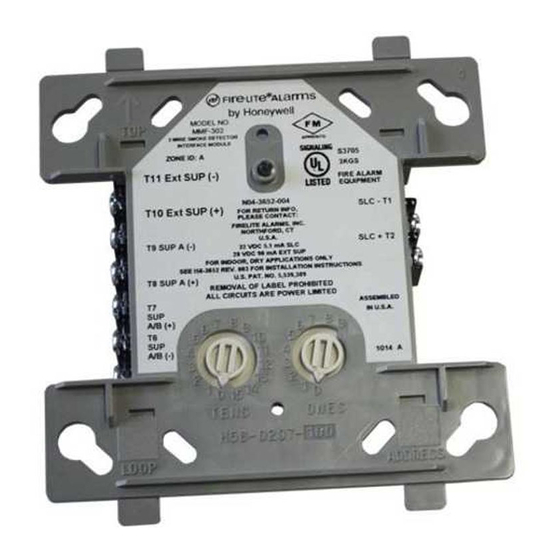
FIGURE 1.
MODULE CONTROLS AND INDICATORS
FIGURE 2.
EXPLODED VIEW OF TYPICAL MODULE
DETAILING MOUNTING ARRANGEMENT
STATUS LED
ROTARY DECADE
ADDRESS SWITCHES
MAGNET TEST
POSITION
A78-2318-00
A78-1327-00
I56-631-06
Advertisement
Table of Contents

Related Manuals for Fire-Lite M302(A


Summary of Contents for Fire-Lite M302(A
- Page 1 TWO-WIRE CONVENTIONAL DETECTOR MONITOR MODULE This information is included with the modules as a quick reference installation guide. Refer to the appropriate Fire-Lite product manual for detailed system information. If the modules will be installed in an existing operational system, inform the operator and local authority that the system will be temporarily out of service.
- Page 2 TESTING The M302(A) monitor module can be tested with a test magnet available from Fire-Lite (M02-04-00, see Figure 1). The magnet test checks the module’s electronics and connections to the control panel. Interfaced two-wire detectors must be tested inde- pendently. Test two-wire detectors per manufacturer’s installation instructions.
- Page 3 C300 SERIES CONTROL MODULE SWITCHING POWER SUPPLY COMMUNICATION LINE 32 VDC MAX. CONNECT MODULES TO LISTED COMPATIBLE ADDRESSABLE FIRE-LITE CONTROL SEE FIRE-LITE PRODUCT MANUAL PANELS ONLY. FOR WIRE SPECIFICATIONS TO NEXT FROM PANEL OR PREVIOUS DEVICE DEVICE (SHIELD) (SHIELD) CONTROL...
- Page 4 Style B (class B) / Style D (class A) EOL Resistance: 3.9K ohm nominal Detector loop current is sufficient to ensure operation of one alarmed detector per zone. For compatible detec- tors refer to the Fire-Lite detector compatibility chart. F400-09-00 I56-631-06 ©Fire-Lite 1994...
Need help?
Do you have a question about the M302(A and is the answer not in the manual?
Questions and answers