Table of Contents
Advertisement
Advertisement
Table of Contents

Related Manuals for Tannoy Ellipse 10 iDP


Summary of Contents for Tannoy Ellipse 10 iDP
-
Page 1: Owners Manual
Owners Manual... -
Page 3: Table Of Contents
Important Safety Instructions Quick Set-Up Guide Introduction Concept & Design Philosophy Unpacking & Visual Checks Preliminary Recommendation Monitor Placement Orientation Master & Slave Concept Rear Panel Description Operational Overview ™ Display & Setup Procedure Set-Ups Set-Up When The Monitors are connected Parameter Description Bass Management Set-Up Menu... - Page 4 IMPORTANT SAFETY INSTRUCTIONS The lightning flash with an arrowhead symbol within an The exclamation point within an equilateral triangle is equilateral triangle, is intended to alert the user to the intended to alert the user to the presence of important presence of uninsulated “dangerous voltage”...
- Page 5 QUICK SETUP GUIDE Below is a quick guide on how to connect different variations of setups. Connections must be made exactly as illustrated. Detailed descriptions of the setups can be found on pages 16-24.
- Page 6 NOTE (7.1 only) If you wish to set up your system with side channels as opposed to five “screen” channels: Simply substitute LI (Left Inner) & RI (Right Inner), for SL (Side Left) & SR (Side Right) as shown in the adjacent diagram. Follow the same format for 7.1 Digital &...
- Page 7 Introduction In order to maintain our leading position in the worldwide professional studio market, the core technologies of Tannoy ™ are constantly being refined. The latest updates have resulted in a fully re-engineered Dual Concentric drive unit and ™ an improved, ultra high performance SuperTweeter , which is a key component within Tannoy’s long-term development...
-
Page 8: Concept & Design Philosophy
20kHz, with consistent amplitude, phase and dispersion. ™ However, the design effort is worth it, as the intrinsic advantages of the Tannoy Dual Concentric are numerous. There is a coincident point source across the frequency spectrum, high, mid and low. -
Page 9: Unpacking & Visual Checks
A wide variety of shapes, techniques, and materials were researched, to arrive at the elegant, functional and eye-catching elliptical cabinet design. The form of the Tannoy Ellipse is significant. Conventional rectangular, sharp cornered boxes tend to suffer from diffraction and reflection problems caused by the cabinet boundaries - the often overlooked cause of many irregularities heard, and emitted sound field degradation measured, in the higher frequency areas. -
Page 10: Speaker Placement
95dBspl for 8 hours per day, can eventually cause permanent hearing loss. Since Tannoy monitors have a natural-sounding flat frequency response and low distortion, it's possible not to be aware just how high the sound level is high while working with them. -
Page 11: Master & Slave Concept
Master & Slave Concept ™ ™ ™ Two types of hardware exist for each Ellipse 8 iDP and Ellipse 10 iDP (with the exception of the Ellipse TS212 iDP subwoofer – Slave only). Master – A Master unit is able to: Receive digital audio on AES/EBU connections (two channels) Receive analog audio (two channels) Send and receive audio and control data via the proprietary TC LINK connection... - Page 12 ™ Slave Monitor & Ellipse TS212 iDP Subwoofer The slave unit is able to receive and distribute audio and control data via the proprietary TC LINK connection Slave Monitor Network Connections The Slave and Sub units contain one RJ45 Input connector and one Link connector. Via the RJ45 input connector the Slave unit is supplied with audio and control data from the Master unit.
- Page 13 Master Unit 1. System controller/slave switch. In the “out” position the monitor operates as a System Controller. * There can only be one system Controller in a setup. In the “in” position the monitor operates as a regular master or a slave unit. 2.
- Page 14 Parameter structure accessible via the Ellipse monitor set as System Controller Empty Custom 999002 L Front Stereo Analog Volume -50.0 dB Stereo Digital Stereo 192 kHz Surround Analog Surround Digital ENTER Surround 192 kHz *Select Mode 5.1 dig/6 master *Select Task No task Bass Management X-over 50Hz...
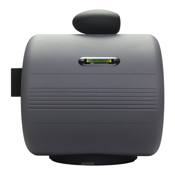
- Page 15 ™ The iDP Display - Master EXIT ENTER INTERACTIVE DIGITAL PROGRAMMING ENTER key CURSOR UP/DOWN key The ENTER key has two main functions: These keys are used for navigating and adjusting To enter the menus currently displayed. parameter values. To set the displayed parameter in Edit mode. When a parameter can be edited via the CURSOR keys a The previous page illustrates how to navigate through ™...
- Page 16 Setups General Setup Procedure Decide which Setup you are going to build. ™ Connect the Ellipse iDP monitors exactly as shown on the following pages. Power up all monitors. Set one of the Master-monitors as the System Controller as shown on the Setup diagrams. Leaving the TC LINK button on the rear panel on the OUT position does this.
- Page 17 Analog Stereo Set-up With Stereo Subs The diagram shows how to connect a stereo set-up with two subwoofers. The Left monitor is set as the System Controller by leaving out the TC Link button on the rear panel. The Left master monitor receives both the left and right input signals via the analog input connectors.
- Page 18 5.1 Analog Set-up The diagram shows how to connect a 5.1 analog set-up. The Centre monitor is set as the System Controller by leaving out the TC Link button on the rear panel. The Centre monitor receives audio for both centre (input 1) & LFE channels (input 2) via the analog input connectors.
- Page 19 5.1 Digital 192kHz Set-up The diagram shows how to connect a 5.1 digital set-up at 192khz. All Master monitors require installed digital I/O cards. AES signal is fed to inputs 2&3 of these cards. The Centre monitor is set as the System Controller by leaving out the TC Link button on the rear panel.
- Page 20 6.1 Digital Set-up The diagram shows how to connect a 6.1 digital set-up. All Master monitors require installed digital I/O cards. AES signal is fed to input 2 of these cards. The Centre monitor is set as the System Controller by leaving out the TC Link button on the rear panel.
- Page 21 7.1 Analog Set-up ™ The diagram shows how to connect a 7.1 SDDS analog set-up. The Centre monitor is set as the System Controller by leaving out the TC Link button on the rear panel. RJ45 Network connections for the system should be connected in the following way: - Centre output to LF input Centre output to RF input...
- Page 22 7.1 Digital 192kHz Set-up The diagram shows how to connect a 7.1 SDDS™ 192kHz set-up. The Centre monitor is set as the System Controller by leaving out the TC Link button on the rear panel. RJ45 Network connections for the system should be connected in the following way: - Centre output to LF input Centre output to RF input...
- Page 23 Connecting Two Subs Two Subs can be connected to any of the above Set-Ups When no Bass management is selected, no signal will be sent to the subwoofers. When Bass management is selected, low frequency content from the left channel is extracted and sent to the left subwoofer. Low frequency content from the right channel is extracted and sent to the right subwoofer.
- Page 24 5.1 Dig/6 - Master The diagram shows how to connect a 5.1 digital set-up using a single master unit. The set-up requires one master monitor with the Digital AES\EBU input card installed, four slave monitors and one subwoofer. The Centre monitor is set as the System Controller by leaving out the TC Link button on the rear panel.
- Page 25 SETUP when the monitors are connected The following is a simple operational setup guide, which is carried out after the monitors are connected. The assumption is made that you will be navigating the menus via the LCD display on the master monitor. If you have purchased the ™...
- Page 26 Reset Procedure Three different levels of “Reset” exist. For the three Reset levels all connected monitors will be affected. Select between the following reset options: - The Reset functions are accessed by holding the ENTER key on the System Controller while powering up: Clear Monitor Settings All global and local parameters in connected monitors are reset.
-
Page 27: Parameter Description
Parameter Description Basic operation in all menus (when navigating the menus via the LCD display) • Use ARROW keys to select value or submenu • Use ENTER to enter menus or for confirmation, and to activate • Use EXIT to step to a higher level or to decline an operation •... -
Page 28: Bass Management
Bass Management Bass management (sometimes called bass redirection) is a very important and useful tool. With conventional studio monitors external electronics is required to achieve bass management. It is in general an absolute necessity if you want to make a multi-channel set-up in a small room.The bass management system is designed to subtract the bass contents of all main ™... - Page 29 Setup Menu • Press ENTER to access sub-menus Setup • Press ENTER to access select mode. Select mode is indicated by “ * ” • Press ENTER to confirm choice Empty Custom Stereo Analog Stereo Digital Stereo 192kHz Surround Analog Surround Digital Surround 192kHz 5.1 dig/6 Master...
- Page 30 ™ ™ Parameters available for Ellipse 8 iDP and Ellipse 10 iDP Pink Noise On/Off Calibrate Level calibration of the selected monitor. Range –6dB to +6dB Rel.Lev. Relative preset volume for the selected monitor relative to the calibrated and global volume. Range –40dB to 0dB Room Position - Neutral...
-
Page 31: Parameter Categories
Parameter Categories Global Parameters These parameters apply to the entire system: - Global parameters stored with presets • Bass Management • Mute Status Global parameters NOT stored with presets • Ref. Levels • Analog Input Sensitivity • Selected Setup • BNC Sync Local Parameters These parameters apply to individual Ellipse monitors: -... - Page 32 ™ Remote ™ The iDP remote is available and can perform the following functions: - Instant access of three different user defined Reference Level settings. Instant Preset Recall function of up to 4 presets. This way you can easily switch between different setups from your listening position.
- Page 33 ™ Remote (cont.) Description of Functions:- REF LEVEL keys 1-3 To recall Reference Levels 1-3: Press relevant key shortly. The key LED indicates activated Reference Level. To set Reference Level 1-3: Set level using the large VOLUME potentiometer on the remote. Press and hold relevant Reference level key for approx. 2 seconds.
-
Page 34: Idp Soft
A Serial to Cat-5 cable is supplied, if a USB port is used, an optional "USB to Serial Port" converter will be required. The "KeySpan USA 19" has been tested by Tannoy and found appropriate. For further information please visit www.keyspan.com or contact Tannoy customer support. - Page 35 ™ iDP SOFT (cont.) ™ This is the Main screen from where all other iDP SOFT screens are accessed. When The (((•))) network icon (upper left corner) ™ ™ Is steady - The computer running the iDP SOFT is not correctly connected to Ellipse iDP monitors.
-
Page 36: Preset List
™ iDP SOFT (cont.) Preset List Clicking on the left side of the display frame accesses the Preset List. Presets include Preset Volume Mute status Bass Management X-curve setting LFE Low Pass LFE Gain ™ Parametric EQ (can only be adjusted using the optional PC Installers Package-PC-iP All other settings can be considered “global”... - Page 37 ™ iDP SOFT (cont.) Network Accessing the Network Screen Press the (((•))) icon in the Main screen to access the Network facilities. In this screen various global network settings are handled. ™ Press <AutoDetect> to scan your COM ports. If an Ellipse iDP System is connected to any port it will be recognized.
- Page 38 ™ iDP SOFT (cont.) During Software upload various messages could be displayed: Example: ™ In a 5.1 iDP setup you are uploading monitor software to the entire system. As there are separate software files for monitors and subs the following message should appear. “5 Ellipse monitors updated successfully”...
- Page 39 Monitor Assignment Task Press monitor symbol to activate pink noise test-tone. Then select task for the monitor now playing the noise. Serial number and type will be indicated. A monitor marked with a question mark indicates that an “unknown” monitor has been detected.
- Page 40 ™ iDP SOFT (cont.) Calibrated Level Level calibration of the selected monitor. Relative Level Preset volume for the selected monitor relative to the calibrated and global volume. Use Parametric EQ ™ This will be marked if the Parametric EQ is activated via the PC-iP program.
- Page 41 ™ iDP SOFT (cont.) Phase Range: 0-180° To time-compensate if the Sub cannot be placed according to the ITU 775 recommendations. There are individual Phase settings for each of the Bass Management Cross-over frequencies. Once set, these are stored as Global settings. Polarity Range: 0 or 180 deg.
- Page 42 Chained monitors If several monitors are chained on the same task (e.g. LSur-LSChain) a dropdown menu will appear as shown below. To calibrate a chained monitor simply select from the list. An indication of Chained monitors will also be shown in the Mainscreen. This symbol indicates that there are two monitors chained on this specific position.
- Page 43 Max. SPL (pair @ mix position) 118dB (continuous) Dispersion (-6dB) 90 degrees Crossover Frequency 1.7kHz(DSP Generated) & 16kHz (Passive) ™ Drive units 200mm (8") Tannoy Dual Concentric ™ ™ 25mm (1") WideBand SuperTweeter Cabinet Volume/LF Alignment 18 Litres/Bass Reflex Dimensions (H x W x D) 373mm x 460mm x 361mm (14 ”...
- Page 44 Max. SPL (pair @ mix position) 122dB (continuous) Dispersion (-6dB) 90 degrees Crossover Frequency 1.4kHz & 21kHz (DSP Generated) ™ Drive units 254mm (10") Tannoy Dual Concentric ™ ™ 25mm (1") WideBand SuperTweeter Cabinet Volume/LF Alignment 30 Litres/Bass Reflex Dimensions (H x W x D) 423mm x 540mm x 391mm (16 ”...
- Page 45 ™ ™ Technical Specifications - Ellipse TS212 iDP Subwoofer & iDP Remote System ™ System, Ellipse TS212 iDP Active Subwoofer Frequency Response 25Hz – 150Hz (+/- 3dB) Max. SPL (@ 1m) 124dB (continuous) Crossover Frequency Set in Bass Management (DSP Generated) Drive units 2 x 300mm (12") Aluminum Cone Cabinet Volume/LF Alignment...
-
Page 46: Performance Data
Performance Data ™ Ellipse 8 iDP Anechoic Frequency Response @ 1m ™ Ellipse 10 iDP Anechoic Frequency Response @ 1m... - Page 47 ™ ™ Dimensions Ellipse 8 iDP / Ellipse 10 iDP 373mm (14.68”) 320mm (12.6”) 460mm (18.11”) 423mm (16.65”) 350mm 540mm (13.78”) (21.26”)
- Page 48 ™ Dimensions Ellipse TS212 iDP (Grey/Silver) 498mm (19.6”) 490mm (19.29”) 520mm (20.47”)
- Page 49 Above -1 dB). This is a warning and you should turn down the Analog input gain Analog Input gain range: +9dBu, +15dBu, +21dBu or 27 dBu. >> PSU error << Displayed if the power supplies fails. The power will be turned off and the monitor will operate. Contact TANNOY Service Department. <Locked> ™...
- Page 50 System Delays Sample Rate Digital Input Analog Input* AES or WC Converter Samples m/seconds Samples @ m/seconds in kHz @ input Rate Converter Rate 32.00 64.00 93.00 2.91 73.00 1.14 44.10 88.20 68.00 1.54 73.00 0.83 48.00 96.00 40.00 0.83 73.00 0.76 64.00...
- Page 52 Cables ™ Below is a guide to the cables used in iDP set-up’s. TC LINK Standard Cat-5 cables Maximum Cable Length : 15 metres. Cable type : Shielded Ethernet Cable Category 5. Connector type : RJ45 This connection carries Digital audio (24 bit) and network control information. P1 (pin No.) P2(pin No.) Colour...
-
Page 53: Declaration Of Conformity
Declaration Of Conformity The following apparatus is/are manufactured in the United Kingdom by Tannoy Ltd of Rosehall Industrial Estate, Coatbridge, Scotland, ML5 4TF and TC Electronic A/S, Sindalsvej 34, 8240 Risskov, Denmark. The following equipment is marked with the CE label and conform(s) to the protection requirements of the European Electromagnetic Compatibility Standards and Directives. - Page 54 Customer Services, Tannoy Ltd, Coatbridge, Strathclyde ML5 4TF T: +44 (0) 1236 420199 F: +44 (0) 1236 428230 DO NOT SHIP ANY PRODUCT TO TANNOY WITHOUT PREVIOUS AUTHORISATION This warranty in no way affects your statutory rights. Our policy commits us to incorporating improvements to our products through continuous research...
- Page 56 Tannoy Loudspeakers are designed and manufactured in Great Britain by: Tannoy Ltd, Rosehall Industrial Estate, Coatbridge, North Lanarkshire, ML5 4TF, SCOTLAND Telephone: +44 (0)1236 420199 Fax: +44 (0)1236 428230 Tannoy North America Inc, Suite 1. 335 Gage Avenue, Kitchener, Ontario, CANADA, N2M 5E1...
Need help?
Do you have a question about the Ellipse 10 iDP and is the answer not in the manual?
Questions and answers