Advertisement
Chevy S-10 &
Part #60: Puller mode, includes thermostatic control.
Part #65: Puller mode, does not include controls.
Installation Instructions
1. Disconnect the battery ground cable.
2. Remove the top (3) shroud screws. Reference
Diagram B
3. Remove the (2) screws on each side of the
upper shroud.
4. Remove the top of the shroud.
5. Remove the (4) nuts securing the clutch/fan
assembly to the water pump shaft and
remove assembly.
6. Reinstall nuts on water pump shaft to secure
water pump pulley.
7. Install spacer and mounting bracket on the
bottom of the electric fan shroud securing
with the nuts and bolts provided. Note:
Shroud holes for mounting brackets are
offset more from edge of shroud on the top
side.
Reference Diagram A for bracket installation
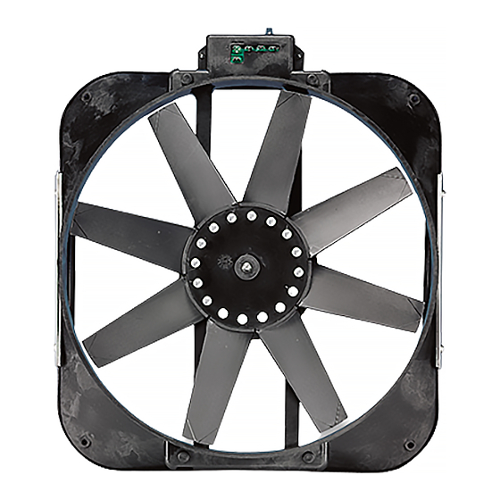
Reference Diagram B for proper fan orientation
Mount Control Module on the
Passenger Side of the Vehicle
8. Lift radiator approximately 2 inches and
hook the bottom mounting bracket under the
lower radiator C-channel so that the fan is
mounted on the center of the radiator Note:
Installation is facilitated by angling the top
of the fan away from the radiator while
hooking the bottom bracket.
9. While holding the top of the electric fan
against the radiator install the top mounting
spacer and bracket using the nuts and bolts
provided.
10. Follow wiring instructions in the next
section.
11. Reinstall upper radiator shroud and fasten
using the original bolts.
12. Reconnect battery ground cable.
S-10
Blazer Electric Fan
Mounting
Bracket
Spacer
Upper Shroud
Top Shroud
Screws
rev. 06-22-05 99925 page 1 of 2
(1982 to 2002)
Diagram A
Control Module
Diagram B
Side Screws
Advertisement
Table of Contents

Subscribe to Our Youtube Channel
Related Manuals for Flex-a-Lite 60


Summary of Contents for Flex-a-Lite 60
- Page 1 S-10 Chevy S-10 & Blazer Electric Fan Part #60: Puller mode, includes thermostatic control. Part #65: Puller mode, does not include controls. (1982 to 2002) Mounting Installation Instructions Bracket Diagram A 1. Disconnect the battery ground cable. Spacer 2. Remove the top (3) shroud screws. Reference Diagram B Control Module 3.
- Page 2 Flex-a-lite Consolidated, 7213-45th St. Ct. E., Fife, WA 98424, Telephone No. 253-922-2700, warrants to the original purchasing user, that all Flex-a-lite products to be free of defects in material and workmanship for a period of 365 days (1 year) from date of purchase. Flex-a-lite products failing within 365 days (1 year) from date of purchase may be returned to the factory through the point of purchase, transportation charges prepaid.
Need help?
Do you have a question about the 60 and is the answer not in the manual?
Questions and answers