Advertisement
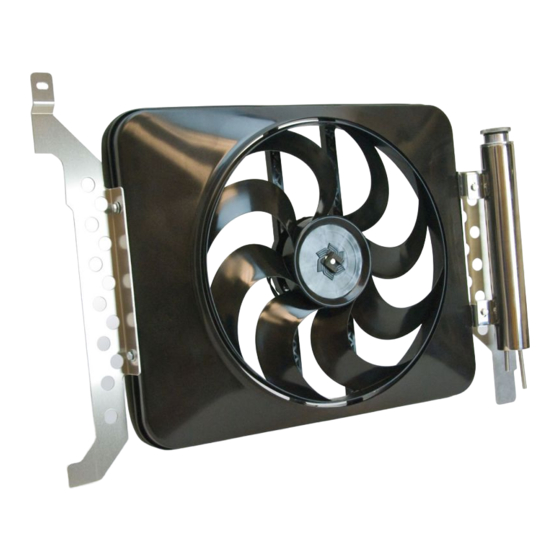
Toyota Tacoma Electric Fan Kit;
'05–'09
#678 with controls
#688 without controls
———INSTALLATION INSTRUCTIONS———
REMOVAL OF EXISTING FAN AND SHROUD ASSEMBLY:
1. Make sure the engine is cool.
2. Disconnect negative (-) battery cable from battery.
3. Remove plastic protective cover from top of engine / intake manifold. Two acorn nuts
located in front are to be removed first. Lift front of cover and notice the cover is hinging
at back. Pull to disconnect at pivot point.
4. Remove plastic cover bridging shroud to top cross member. (9 ea) Push-type plastic
rivets need to be removed (see Detail 1). Prying each center post up with a flat-end
screwdriver will release fastener.
5. Remove overflow hose from radiator filler neck.
6. Remove top bolts (2ea.) holding fan shroud to radiator side tanks. Save bolts for instal-
lation of new shroud (see Detail 2).
7. Remove (4ea.) nuts securing fan-clutch assembly (see Detail 3); then pull fan-clutch
assembly and shroud out simultaneously.
8. Important: Re-secure pulley with new washers of kit bag #13615 and original pulley
nuts.
Plastic Cover
Detail 1
Plastic Rivets
Save bolts for new installation
Detail 2
rev. 04-20-09 part no. 99678 Page 1 of 4
Advertisement
Table of Contents

Related Manuals for Flex-a-Lite 678


Summary of Contents for Flex-a-Lite 678
-
Page 1: Installation Instructions
Toyota Tacoma Electric Fan Kit; '05–'09 #678 with controls #688 without controls ———INSTALLATION INSTRUCTIONS——— REMOVAL OF EXISTING FAN AND SHROUD ASSEMBLY: 1. Make sure the engine is cool. 2. Disconnect negative (-) battery cable from battery. 3. Remove plastic protective cover from top of engine / intake manifold. Two acorn nuts located in front are to be removed first. - Page 2 Detail 3 Detail 4a INSTALLATION OF NEW ELECTRIC FAN SHROUD: 1. Mount bracket #67802 to driver’s side of shroud. Use the hex bolts and washers provided. Note: Leave the bracket loosely mounted for now; you will adjust and tighten them later (see Detail 4 & 4a).
-
Page 3: Wiring Diagram
NOTE: To prevent thermostatic activation (if only manual switch operation is desired), omit the lead to the "+" terminal of the control box. "B", "G", "M+" and "M-" must re- main connected. If not using a Flex-a-lite manual switch, do not connect a ground wire to the switch! - Page 4 Flex-a-lite Consolidated, 7213-45th St. Ct. E. Fife, WA 98424, Telephone No. 253-922-2700, warrants to the original purchasing user, that all Flex-a-lite products to be free of defects in material and workmanship for a period of 365 days (1 year) from date of purchase. Flex-a-lite products failing within 365 days (1 year) from date of purchase may be returned to the factory through the point of purchase, transportation charges prepaid.
Need help?
Do you have a question about the 678 and is the answer not in the manual?
Questions and answers