Bryant 598B Installation And Start-Up Instructions Manual
Two-speed puron plus air conditioning unit
Hide thumbs
Also See for 598B:
- User manual (40 pages) ,
- Installation and start-up instructions manual (20 pages)
Table of Contents
Advertisement
NOTE: Read the entire instruction manual before starting the
This symbol
indicates a change since the last issue.
SAFETY CONSIDERATIONS
Improper installation, adjustment, alteration, service, maintenance,
or use can cause explosion, fire, electrical shock, or other
conditions which may cause death, personal injury, or property
damage. Consult a qualified installer, service agency, or your
distributor or branch for information or assistance. The qualified
installer or agency must use factory-authorized kits or accessories
when modifying this product. Refer to the individual instructions
packaged with the kits or accessories when installing.
Follow all safety codes. Wear safety glasses, protective clothing,
and work gloves. Use quenching cloth for brazing operations.
Have fire extinguisher available. Read these instructions thor-
oughly and follow all warnings or cautions included in literature
and attached to the unit. Consult local building codes and National
Electrical Code (NEC) for special requirements.
Recognize safety information. This is the safety-alert symbol
When you see this symbol on the unit and in instructions or
manuals, be alert to the potential for personal injury.
Understand these signal words; DANGER, WARNING, and
CAUTION. These words are used with the safety-alert symbol.
DANGER identifies the most serious hazards which will result in
severe personal injury or death. WARNING signifies hazards
which could result in personal injury or death. CAUTION is used
to identify unsafe practices which would result in minor personal
injury or product and property damage. NOTE is used to highlight
suggestions which will result in enhanced installation, reliability,
or operation.
WARNING: Before installing, modifying, or servicing
system, main electrical disconnect switch must be in the
OFF position. There may be more than 1 disconnect
switch. Lock out and tag switch with a suitable warning
label. Electrical shock can cause personal injury or death.
CAUTION: Puron® (R-410A) systems operate at higher
pressures than standard R-22 systems. Be certain that
service equipment is rated for Puron®. Some R-22
service equipment may not be acceptable. Check with
your distributor.
INSTALLATION RECOMMENDATIONS
NOTE: In some cases noise in the living area has been traced to
gas pulsations from improper installation of equipment.
1. Locate unit away from windows, patios, decks, etc. where
unit operation sound may disturb customer.
2. Ensure that vapor and liquid tube diameters are appropriate
to capacity of unit.
installation and
Start-Up instructions
TWO-SPEED PURON® PLUS
AIR CONDITIONING UNIT
.
—1—
Cancels: II 598B-24-3
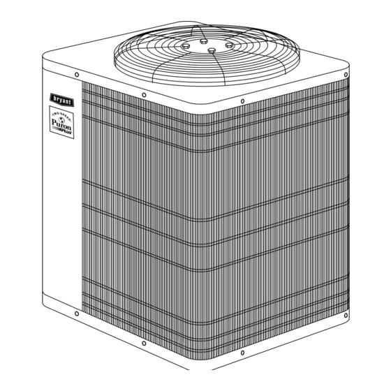
Fig. 1—Model 598B
3. Run refrigerant tubes as directly as possible by avoiding
unnecessary turns and bends.
4. Leave some slack between structure and unit to absorb
vibration.
5. When passing refrigerant tubes through the wall, seal
opening with RTV or other pliable silicon-based caulk. (See
Fig. 2.)
6. Avoid direct tubing contact with water pipes, duct work,
floor joists, wall studs, floors, and walls.
7. Do not suspend refrigerant tubing from joists and studs with
a rigid wire or strap which comes in direct contact with
tubing. (See Fig. 2.)
8. Ensure that tubing insulation is pliable and completely
surrounds vapor tube.
9. When necessary, use hanger straps which are 1 in. wide and
conform to shape of tubing insulation. (See Fig. 2.)
10. Isolate hanger straps from insulation by using metal sleeves
bent to conform to shape of insulation.
When outdoor unit is connected to factory-approved indoor unit,
outdoor unit contains system refrigerant charge for operation with
indoor unit of the same size when connected by 15 ft of
field-supplied or factory accessory tubing. For proper unit opera-
tion, check refrigerant charge using charging information located
on control box cover.
IMPORTANT: Maximum liquid-line size is 3/8-in. O.D. for all
residential applications.
IMPORTANT: Always install the factory-supplied Puron® air
conditioner liquid line filter drier. Obtain replacement filter driers
from your local distributor or branch.
598B
II 598B-24-4
5-03
A01050
Advertisement
Table of Contents

Related Manuals for Bryant 598B


Summary of Contents for Bryant 598B
- Page 1 installation and 598B start-up instructions TWO-SPEED PURON® PLUS AIR CONDITIONING UNIT Cancels: II 598B-24-3 II 598B-24-4 5-03 NOTE: Read the entire instruction manual before starting the installation. This symbol indicates a change since the last issue. SAFETY CONSIDERATIONS Improper installation, adjustment, alteration, service, maintenance, or use can cause explosion, fire, electrical shock, or other conditions which may cause death, personal injury, or property damage.
- Page 2 NOTE: Avoid contact between tubing and structure OUTDOOR WALL INDOOR WALL CAULK LIQUID TUBE VAPOR TUBE INSULATION THROUGH THE WALL JOIST HANGER STRAP (AROUND VAPOR INSULATION TUBE ONLY) VAPOR TUBE ⁄ ⁄ IN. DIA TIEDOWN KNOCKOUTS (2) PLACES IN BASEPAN A97375 1 MIN.
- Page 3 2. Remove coil access panel and fitting panel from front of cabinet. 3. Remove TXV support clamp using the 5/16-in. nut driver. Save the clamp. 4. Remove TXV using a backup wrench on flare connections INLET to prevent damage to tubing. 5.
- Page 4 SENSING BULB CAUTION: If ANY refrigerant tubing is buried, provide 6–in. vertical rise at service valve. Refrigerant tubing lengths up to 36 in. may be buried without further special STRAP consideration. Buried refrigerant tubing lengths greater than 36 in. are NOT recommended. SUCTION TUBE CAUTION: To prevent damage to unit or service valves,...
- Page 5 LIQUID-LINE 5000 FILTER-DRIER 4500 LIQUID 4000 SERVICE LEAK IN 3500 VALVE SYSTEM 3000 2500 2000 CONNECTOR VACUUM TIGHT TUBE 1500 TOO WET 1000 TIGHT DRY SYSTEM A95424 MINUTES A95509 A95424 Fig. 7—Filter Drier with Sweat Adapter Tube Fig. 8—Deep Vacuum Graph and Liquid Tube EVACUATE G.
- Page 6 DISCONNECT high-speed airflow until humidistat closes. Fig. 11 shows the PER N. E. C. AND/ OR LOCAL CODES wiring with a Bryant Thermidistat which controls temperature and CONTACTOR humidity level without the need for an additional humidistat and relay. FIELD POWER...
- Page 7 THERMIDISTAT VARIABLE-SPEED TWO-STAGE THERMIDISTAT CONTROL CONDENSING TWO-SPEED FURNACE CONTROL MODEL RH FURNACE AIR CONDITIONER WITH PSC TWO-SPEED MODEL RH BLOWER MOTOR AIR CONDITIONER O/W2 HEAT STAGE 2 O/W2 HEAT STAGE 2 Y1/W2 COOL STAGE 1 Y1/W2 COOL STAGE 1 W/W1 HEAT STAGE 1 W/W1 HEAT STAGE 1...
- Page 8 PROGRAMMABLE VARIABLE SPEED SINGLE-STAGE TWO-SPEED 80% NON-CONDENSING FURNACE THERMOSTAT FURNACE AIR CONDITIONER MODEL 2S NON-PROGRAMMABLE BOARD COOL STAGE 1 Y1/W2 THERMOSTAT MODEL 2S TWO-SPEED FURNACE AIR CONDITIONER COOL STAGE 1 Y1/W2 BOARD HEAT STAGE 1 W/W1 O/W2 HEAT STAGE 2 COOL STAGE 2 Y/Y2 HEAT STAGE 1...
- Page 9 PROGRAMMABLE THERMIDISTAT FK4C, FV4A TWO-SPEED FK4C, FV4A THERMOSTAT CONTROL TWO-SPEED OR 40FK AIR CONDITIONER OR 40FK MODEL RH MODEL 2S AIR CONDITIONER FAN COIL FAN COIL HEAT STAGE 2 O/W2 REMOVE J2 JUMPER FOR HEAT STAGING JUMPER HEAT STAGE 1 W/W1 24 VAC HOT Y1/W2...
-
Page 10: Wiring Diagram Notes
LEGEND 24-V FACTORY WIRING 24-V FIELD WIRING FIELD SPLICE CONNECTION RELAY SPDT, PILOT DUTY 24-V COIL (HN61KK324) OR EQUIVALENT HUMIDISTAT, OPENS ON HUMIDITY RISE (HL38MG026) AIRFLOW SELECTOR A97466 WIRING DIAGRAM NOTES: 1. WIRING MUST CONFORM TO NEC OR LOCAL CODES. 2. - Page 11 NOTE: Bryant electronic thermostats are equipped with a 15 minute staging timer. This timer prevents the two-speed system from operating at high speed until unit has been operating in low speed for 15 minutes unless there is at least a 5°F difference...
- Page 12 TABLE 4—SUBCOOLING TEMPERATURES TABLE 5—CONTROL FUNCTION LED CODE TXV TYPE EXPANSION DEVICE SIGNAL CODE DEFINITION UNIT HIGH CAPACITY ONLY IMPORTANCE* SUBCOOLING AT SERVICE VALVE Constant flash No demand 14°F No pause Stand by 15°F 1 flash Low-speed operation w/pause 12°F 2 flashes 16°F High-speed operation...
- Page 13 I. PRESSURE SWITCH PROTECTION THERMISTOR CURVE The outdoor unit is equipped with high- and low-pressure switches. If the control senses the opening of a high or low pressure switch, it will respond as follows: 1. De-energize the compressor low or high speed contactor, 2.
- Page 14 1. Ensure that all wiring and tubing is secure in unit before adding panels and covers. Securely fasten all panels and covers. 2. Tighten service valve stem caps to 1/12 turn past finger Control Box tight. Side of Unit 3. Leave Owner’s Manual with owner. Explain system opera- tion and periodic maintenance requirements outlined in manual.
- Page 15 DUAL CAPACITY CONNECTION DIAGRAM 208 / 230 - 1 - 60 POWER SUPPLY EQUIP GND NOTE #11 COMP HP/AC START YEL/PNK FORCED COMP YEL/PNK DEFROST BLU/PNK BLU/PNK DEFROST TIME (MIN) START RELAY COMM STATUS FAN CAP A B C D TO INDOOR UNIT A01513 Fig.
- Page 16 RELAY COMM STATUS OC T FAN CAP A B C D TO INDOOR UNIT A02212 Fig. 16—Wiring Diagram—060 © 2003 Bryant Heating & Cooling Systems 7310 W. Morris St. Indianapolis, IN 46231 —16— Printed in U.S.A. ii598b244 Catalog No. 5359-810...
Need help?
Do you have a question about the 598B and is the answer not in the manual?
Questions and answers