Bryant Preferred Series Installation Instructions Manual
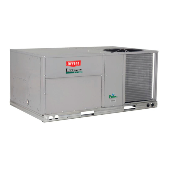
Single package rooftop
Hide thumbs
Also See for Preferred Series:
- Service and maintenance instructions (96 pages) ,
- Installation instructions manual (68 pages) ,
- Manual (68 pages)
Table of Contents
Advertisement
Quick Links
Preferred™ Series 581K*04-06F
Single Package Rooftop
Ultra Low NOx (14 ng/J) Gas Heating/Electric Cooling Unit
with Puron
(R-410A) Refrigerant
®
CONTENTS
SAFETY CONSIDERATIONS . . . . . . . . . . . . . . . . . . . . . . 2
Model Number Nomenclature and Dimensions . . . . . . . . . 3
Rated Indoor Airflow . . . . . . . . . . . . . . . . . . . . . . . . . . . . . . 3
INSTALLATION . . . . . . . . . . . . . . . . . . . . . . . . . . . . . . . . . 8
Jobsite Survey . . . . . . . . . . . . . . . . . . . . . . . . . . . . . . . . . . . . 8
Step 1 - Plan for Unit Location . . . . . . . . . . . . . . . . . . . . . 8
Step 2 - Plan for Sequence of Unit Installation . . . . . . . . 8
Step 3 - Inspect Unit . . . . . . . . . . . . . . . . . . . . . . . . . . . . . . 8
Step 4 - Provide Unit Support . . . . . . . . . . . . . . . . . . . . . . 8
• ALTERNATE UNIT SUPPORT (IN LIEU OF CURB OR
Step 5 - Field Fabricate Ductwork . . . . . . . . . . . . . . . . . 10
Step 6 - Rig and Place Unit . . . . . . . . . . . . . . . . . . . . . . . 10
(When Required) . . . . . . . . . . . . . . . . . . . . . . . . . . . . . . 11
Step 8 - Install Outside Air Hood . . . . . . . . . . . . . . . . . . 12
Step 9 - Units with Hinged Panels Only . . . . . . . . . . . . . 13
Step 10 - Install Flue Hood . . . . . . . . . . . . . . . . . . . . . . . 13
Step 11 - Install Gas Piping . . . . . . . . . . . . . . . . . . . . . . . 13
(GAS CONNECTIONS)
Step 13 - Make Electrical Connections . . . . . . . . . . . . . 17
Manufacturer reserves the right to discontinue, or change at any time, specifications or designs without notice and without incurring obligations.
Catalog No. 04-53581025-01
Installation Instructions
Page
Printed in U.S.A.
Form II581K-F-4-6-01 Rev. A
Integrated Gas Controller . . . . . . . . . . . . . . . . . . . . . . . . . 26
EconoMi$er® X (Factory Option) . . . . . . . . . . . . . . . . . . 29
RTU Open Controller (Factory Option) . . . . . . . . . . . . . 41
Controller Options . . . . . . . . . . . . . . . . . . . . . . . . . . . . . . . 41
Smoke Detectors . . . . . . . . . . . . . . . . . . . . . . . . . . . . . . . . . 41
Step 14 - Adjust Factory-Installed Options . . . . . . . . . . 43
Step 15 - Install Accessories . . . . . . . . . . . . . . . . . . . . . . 43
Step 16 - Fan Speed Set Up . . . . . . . . . . . . . . . . . . . . . . . 43
START-UP CHECKLIST . . . . . . . . . . . . . . . . . . . . . . . . CL-1
Pg 1
8-21
Replaces: New
Advertisement
Table of Contents

Related Manuals for Bryant Preferred Series


Summary of Contents for Bryant Preferred Series
-
Page 1: Table Of Contents
Preferred™ Series 581K*04-06F Single Package Rooftop Ultra Low NOx (14 ng/J) Gas Heating/Electric Cooling Unit with Puron (R-410A) Refrigerant ® Installation Instructions CONTENTS Page • FACTORY-OPTION THRU-BASE CONNECTIONS (ELECTRICAL CONNECTIONS) SAFETY CONSIDERATIONS ..... . 2 •... -
Page 2: Safety Considerations
SAFETY CONSIDERATIONS WARNING Installation and servicing of air-conditioning equipment can be hazardous due to system pressure and electrical components. Only PERSONAL INJURY AND ENVIRONMENTAL trained and qualified service personnel should install, repair, or HAZARD service air-conditioning equipment. Failure to follow this warning could cause personal injury or Untrained personnel can perform basic maintenance functions of death. -
Page 3: Model Number Nomenclature And Dimensions
WARNING CAUTION FIRE HAZARD Do not detach the burner box from the heat exchanger panel. If the burner box must be replaced, refer to the Service and Failure to follow this warning could result in severe person- Maintenance Instructions for the unit. al injury and/or property damage. - Page 4 Position: 9 10 11 12 13 14 15 16 17 Example: Unit Type Packaging and Control 581 - Gas Heat RTU A = Standard Packaging, electro-mechanical Preferred™ Series controls, no intake or exhaust option. Will allow for use of all field-installed economizers, manual or 2-position damper.
- Page 5 Fig. 2 — Unit Dimensional Drawing...
- Page 6 Fig. 2 — Unit Dimensional Drawing (cont)
- Page 7 Fig. 2 — Unit Dimensional Drawing (cont)
-
Page 8: Installation
INSTALLATION Step 2 — Plan for Sequence of Unit Installation The support method used for this unit will dictate different se- Jobsite Survey quences for the steps of unit installation. For example, on curb- Complete the following checks before installation. mounted units, some accessories must be installed on the unit 1. - Page 9 ROOF CURB NOTES: POWER WIRING CONTROL WIRING ACCESSORY CONVENIENCE CONNECTOR PKG. ACC. GAS CONNECTION TYPE GAS FITTING ACCESSORY # 1. ROOFCURB ACCESSORY IS SHIPPED DISASSEMBLED. FITTING FITTING OUTLET WIRING CONNECTOR 2. INSULATED PANELS: 25.4 [1"] THK. POLYURETHANE FOAM, 44.5 [1-3/4] # DENSITY. 14"...
-
Page 10: Slab Mount (Horizontal Units Only)
NOTE: The gasketing of the unit to the roof curb is critical for a Insulate and weatherproof all external ductwork, joints, and watertight seal. Install gasket supplied with the roof curb as shown roof openings with counter flashing and mastic in accordance in Fig. -
Page 11: Step 7 - Convert To Horizontal And Connect Ductwork
"B" DETAIL "A" 36"- 54" PLACE ALL SEAL STRIP IN PLACE REQUIRED (914-1371) BEFORE PLACING UNIT ON ROOF CURB. SPREADER BARS DUCT END "C" "A" SEE DETAIL "A" DIMENSIONS MAX WEIGHT UNIT 581K*04F 74.5 1890 36.5 33.5 581K*05F 74.5 1890 36.5 33.5 581K*06F... -
Page 12: Step 8 - Install Outside Air Hood
SCREWS HOOD PARTS PLASTIC TIE WRAP QTY (2) DUCT COVERS SHEET METAL FACE UP SCREWS FOR METAL TRAY QTY (2) BASEPAN Fig. 10 — Economizer Hood Parts Location ECONOMIZER HOOD NOTE: If the power exhaust accessory is to be installed on the unit, the hood shipped with the unit will not be used and must be Fig. -
Page 13: Step 9 - Units With Hinged Panels Only
COMPRESSOR DOOR OUTDOOR COIL PANEL LATCH Fig. 14 — Compressor Door Latch Location PANEL CAULK Step 10 — Install Flue Hood HERE INDOOR INDOOR Flue hood is shipped screwed to the basepan beside the burner COIL COIL ACCESS ACCESS compartment access panel. Remove from shipping location and PANEL PANEL using screws provided, install flue hood and screen in location... -
Page 14: Factory Option Thru-Base Connections
Table 4 — Natural Gas Manifold Pressure UNIT MODEL UNIT SIZE MANIFOLD PRESSURE 3.2 in. wg 581K*--F 04, 05, 06 (797 Pa) CAUTION EQUIPMENT DAMAGE Failure to follow this caution may result in equipment damage. When connecting the gas line to the unit gas valve, the installer MUST use a backup wrench to prevent damage to the valve. - Page 15 Check tightness of connector lock nuts before connecting gas piping. Install a -in. NPT street elbow on the thru-base gas fitting. Attach a -in. pipe nipple with minimum length of 16-in. 9” (229 mm) MIN (406 mm) (field-supplied) to the street elbow and extend it through the access panel at the gas support bracket.
-
Page 16: Step 12 - Install External Condensate Trap And Line
disconnected from the gas valve during the testing of the piping systems when test pressure is in excess of 0.5 psig (3450 Pa). Pres- ATTENTION sure test the gas supply piping system at pressures equal to or less than 0.5 psig (3450 Pa). The unit heating section must be isolated After the installation of the unit gas piping and prior to gas from the gas piping system by closing the external main manual heat start up, ensure that the distances between the main burner... -
Page 17: Step 13 - Make Electrical Connections
When using the standard side drain connection, ensure the red leads. See Convenience Outlets on page 19 for power transformer plug in the alternate bottom connection is tight. Do this before connections. setting the unit in place. The red drain pan can be tightened with The field power wires are connected to the unit at line-side -in. -
Page 18: Units With Factory-Installed Non-Fused Disconnect
UNITS WITH FACTORY-INSTALLED NON-FUSED DISCONNECT The factory-installed option non-fused disconnect (NFD) switch is located in a weatherproof enclosure located under the main control box. The manual switch handle and shaft are shipped in the disconnect enclosure. Assemble the shaft and handle to the switch at this point. -
Page 19: Convenience Outlets
CONVENIENCE OUTLETS WARNING ELECTRICAL OPERATION HAZARD Failure to follow this warning could result in personal injury or death. Units with convenience outlet circuits may use multiple disconnects. Check convenience outlet for power status before opening unit for service. Locate its disconnect switch, if appropriate, and open it. -
Page 20: Factory-Option Thru-Base Connections (Electrical Connections)
Operation on im- proper line voltage or excessive phase imbalance constitutes abuse and may cause damage to electrical components. Such operation would invalidate any applicable Bryant warranty. max voltage deviation from average voltage % Voltage... -
Page 21: Field Control Wiring
Systems (RTU Open is available as a factory-installed RACEWAY option only). THERMOSTAT Install a Bryant-approved accessory thermostat according to installation instructions included with the accessory. For com- plete economizer function, select a two-stage cooling thermo- stat. Locate the thermostat accessory on a solid wall in the con- ditioned space to sense average temperature in accordance with the thermostat installation instructions. -
Page 22: Typical Unit Wiring Diagrams
Connecting a Field-Supplied Thermidistat device The Thermidistat has dry contacts at terminals D1 and D2 for dehumidification operation (see Fig. 38). Connect D1 to the Route the Thermidistat multi-conductor thermostat cable R terminal on the UCB. Connect D2 to the HUM terminal on (field-supplied) through the hole provided in the unit corner post. - Page 23 Fig. 39 — Typical Control Wiring Diagram, Electro-Mechanical with W7220 (581K*04-06F/K 208/230-3-60 Unit Shown)
- Page 24 Fig. 40 — Typical Control Wiring Diagram, RTU Open Controller (581K*04-06F/K 208/230-3-60 Unit Shown)
- Page 25 Fig. 41 — Typical Power Wiring Diagram – 581K*04-06F/K with Electro-Mechanical Controller, 208/230-3-60 Unit Shown...
-
Page 26: Integrated Gas Controller
Integrated Gas Controller and limit switch are closed, and that the pressure switch is open. If the check was successful, the induced draft motor is energized. The unit contains an Integrated Gas Controller (IGC) board. When the pressure in the heat exchanger is low enough to close The IGC control board uses a flue gas pressure switch that the pressure switch, the ignition activation period begins. - Page 27 UNIT CONTROL BOARD Fig. 44 — Typical IGC Control Wiring Diagram Table 5 — IGC Board LED Alarm Codes FLASH SYMPTOM CAUSE REMEDY CODE Normal Operation — — No Power or Hardware Failure Loss of power to control module Check 5-amp fuse on the ICG, power to unit, 24V circuit breaker, (IGC) and transformer.
- Page 28 Pre-purge: Induced draft motor Ignition: Gas valve and Call for heat: starts and runs for 30 seconds at igniter energize for 2 W terminal is energized ignition speed, Speed 1 seconds Rectification: Flame sensor activates for 2 seconds after Gas valve and igniter ignition period de-energerized Is flame...
-
Page 29: Economi$Er® X (Factory Option)
EconoMi$er X (Factory Option) ® Electrical • Rated Voltage — 20 to 30 Vac RMS, 50/60 Hz The EconoMi$er X system is an expandable economizer con- trol system, which includes a W7220 economizer module (con- • Transformer — 100 va maximum system input troller) with an LCD and keypad (see Fig. -
Page 30: Economizer Module Wiring Details
Relative Humidity Table 7 — Economizer Module - Right Hand Terminal Blocks 5% to 95% RH non-condensing LABEL TYPE DESCRIPTION ECONOMIZER MODULE WIRING DETAILS TOP RIGHT TERMINAL BLOCKS Use Fig. 47 and Tables 6 and 7 to locate the wiring terminals AUX2 I 24 vac IN The first terminal is not used. -
Page 31: Co2 Sensor Wiring
To use the keypad when working with menus: Table 8 — HH57AC081 Sensor Wiring Terminations • Press the ▲ (Up arrow) button to move to the previous menu. • Press the ▼ (Down arrow) button to move to the next menu. TERMINAL TYPE DESCRIPTION... -
Page 32: Setup And Configuration
SETUP AND CONFIGURATION IMPORTANT: Table 10 illustrates the complete Before being placed into service, the W7220 Economizer mod- hierarchy. Your menu parameters may be different ule must be set up and configured for the installed system. depending on your configuration. For example, if you do not have a DCV (CO ) sensor, IMPORTANT: During setup, the economizer module is... - Page 33 Table 10 — W7220 Menu Structure* PARAMETER PARAMETER MENU PARAMETER DEFAULT RANGE AND NOTES VALUE INCREMENT † FIRST STAGE COOLING DEMAND (Y1–IN) ECONO AVAIL YES/NO YES = economizing available; the system can use outside air for free cooling when required FIRST STAGE COOLING RELAY OUTPUT ECONOMIZING YES/NO...
- Page 34 Table 10 — W7220 Menu Structure* (cont) PARAMETER PARAMETER MENU PARAMETER DEFAULT RANGE AND NOTES VALUE INCREMENT † MECH COOL ON Displays stage of mechanical cooling that is active. 0, 1, or 2 HEAT STAGES ON Displays the stage of heat pump heating that is active. STATUS SUPPLY FAN SPEED (cont)
- Page 35 Table 10 — W7220 Menu Structure* (cont) PARAMETER PARAMETER MENU PARAMETER DEFAULT RANGE AND NOTES VALUE INCREMENT † 0°F to 50°F ENERGY RECOVERY VENTILATOR UNIT OUTDOOR AIR ERV OAT SP 32°F (–18°C to 10°C); TEMPERATURE SETPOINT †† increment by 1°F Only displayed when AUX1 O = ERV Exhaust fan set point for single speed units.
- Page 36 Table 10 — W7220 Menu Structure* (cont) PARAMETER PARAMETER MENU PARAMETER DEFAULT RANGE AND NOTES VALUE INCREMENT † COOLING STAGE 3 DELAY 0 min, 5 min, Delay after stage 2 cool has been active. Turns on second stage of 15 min, then cooling when economizer is first stage and mechanical cooling is STG3 DLY 2.0h...
- Page 37 Table 10 — W7220 Menu Structure* (cont) PARAMETER PARAMETER MENU PARAMETER DEFAULT RANGE AND NOTES VALUE INCREMENT † DISCHARGE AIR S-BUS SENSOR ERROR DA SYLK T ERR Discharge air sensor has failed or become disconnected - check wiring then replace sensor if the alarm continues. OUTSIDE AIR TEMPERATURE SENSOR ERROR OA SENS T ERR Outdoor air temperature sensor has failed or become disconnected...
-
Page 38: Enthalpy Settings
ENTHALPY SETTINGS point are all below the selected boundary, the economizer sets the economizing mode to YES, economizing is available. When the OA temperature, enthalpy and dew point are below When all of the OA conditions are above the selected bound- the respective setpoints, the Outdoor Air can be used for econ- ary, the conditions are not good to economize and the mode is omizing. -
Page 39: Standard Or Single Speed Fan Operation
STANDARD OR SINGLE SPEED FAN OPERATION The W (heating mode) is not controlled by the W7220 but it re- quires the status to know where to position the OA damper for FAN TYPE = 1SPEED is not used on 581K***F/K units. minimum position for the fan speed. -
Page 40: 2Sp H/C (2 Speed Heat/Cool) Fan Operation
2SP H/C (2 SPEED HEAT/COOL) FAN OPERATION this reduction in fan speed during heat, the economizer FAN TYPE must be set to keep the appropriate outside air intake. FAN TYPE = 2SP H/C is not used on 581K***F/K units. On single phase 581K***F/K units, if reduced the heating fan 3 SPEED FAN OPERATION (SINGLE PHASE UNITS ONLY) speed is lower than the high cooling speed and higher than the low cooling speed, hence the medium speed name. -
Page 41: Checkout
CHECKOUT Inspect all wiring connections at the economizer module’s ter- CAUTION minals, and verify compliance with the installation wiring dia- grams. For checkout, review the Status of each configured pa- EQUIPMENT DAMAGE HAZARD rameter and perform the Checkout tests. Failure to follow this caution may result in equipment damage. NOTE: For information about menu navigation and use of the Be sure to allow enough time for compressor start-up and keypad see Interface Overview on page 31. - Page 42 Completing Return Air Smoke Sensor Installation Unscrew the two screws holding the return air smoke detector assembly. See Fig. 53, Step 1. Save the screws. RETURN AIR SMOKE DETECTOR Turn the assembly 90 degrees and then rotate end to end. (AS SHIPPED) Make sure that the elbow fitting is pointing down.
-
Page 43: Step 14 - Adjust Factory-Installed Options
Fig. 54 — EconoMi$er IV Wiring Step 14 — Adjust Factory-Installed Options • Differential enthalpy sensor • sensor SMOKE DETECTORS • Louvered hail guard Smoke detector(s) will be connected at the Unit Control Board • Phase monitor control (UCB), at terminals marked “Smoke Shutdown.” Detach the jumper covering the Smoke Shutdown terminals on the UCB Refer to separate installation instructions for information on and then attach the wiring harness from the smoke detector. - Page 44 FAN SPEED SET UP CONTROLS Fig. 55 — UCB Fan Speed Controls - 3-Phase Units FAN SPEED SET UP CONTROLS Fig. 56 — UCB Fan Speed Controls - Single Phase Units NOTE: On single phase units, the approximate static pressure of the ductwork must be set for optimal unit efficiency.
- Page 45 ESP in. wg Factory Setting: Calculator 9.0 V 1500 Field Setting: 1625 Record field setting here 10.0 1750 1875 2000 Switch Range: 2125 2250 4.1 - 7.5 2375 6.9 - 8.7 2500 7.7 - 10.0 Field Accessories: Economizer * Overlap in A, B, C switch range designed for maximum field adjustment potential.
- Page 46 Form No: II581K-F-4-6-01 Rev. A © 2021 Carrier Cat. No. 04-53581025-01 Edition Date: 8-21 Printed in U.S.A. Manufacturer reserves the right to change, at any time, specifications and designs without notice and without obligations. Replaces: New...
- Page 47 START-UP CHECKLIST FOR 581K*04-06F/K SINGLE PACKAGE ROOFTOP GAS HEATING/ELECTRIC COOLING UNIT (Remove and use for job file) NOTE: To avoid injury to personnel and damage to equipment or property when completing the procedures listed in this start-up checklist, use good judgment, follow safe practices, and adhere to the safety considerations/information as outlined in preceding sections of this Installation Instruction document.
- Page 48 PRESSURES Gas Inlet Pressure in. wg _____________ in. wg Gas Manifold Pressure STAGE 1 _____________ in. wg STAGE 2 _____________ in. wg Refrigerant Suction CIRCUIT A _____________ PSIG CIRCUIT B _____________ PSIG Refrigerant Discharge CIRCUIT A _____________ PSIG CIRCUIT B _____________ PSIG Verify Refrigerant Charge using Charging Charts (Y/N) _____ GENERAL...
Need help?
Do you have a question about the Preferred Series and is the answer not in the manual?
Questions and answers