Table of Contents
Advertisement
Advertisement
Table of Contents

Related Manuals for Bell'O 8315


Summary of Contents for Bell'O 8315
- Page 2 Introduction Congratulations on your decision to mount your TV with a TV Wall Mounting Kit For Dummies. The enclosed mounting bracket was engineered and designed by Bell’O International Corporation using the latest computer-aided design and stress-analysis software to ensure safety and durability when installed according to the instructions. It has been further tested and Listed by Underwriters Laboratories.
- Page 3 • Improper installation of this product may cause damage or serious injury. Bell'O International Corporation cannot be liable for direct or indirect damage or injury caused by incorrect mounting, incorrect use, or incorrect assembly.
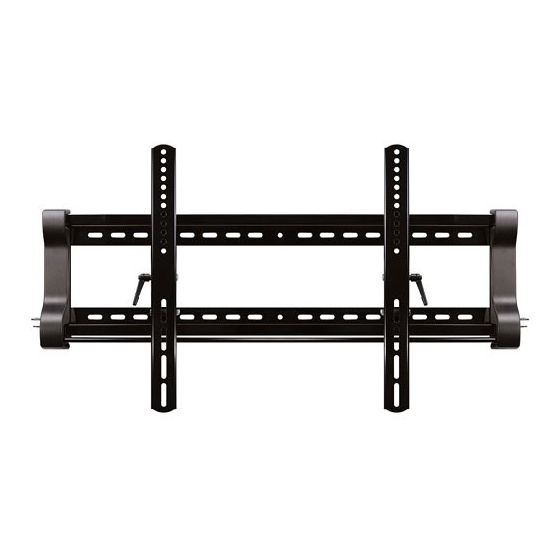
- Page 4 Parts Included in This Kit (WP) 8315 or 8325 Wall Plate (8325 Shown), Quantity: 1 (IG) Installation Guide & DVD, Quantity: 1 each (MA) Monitor Arms, Quantity: 2 (IT) Installation Template, Quantity: 1 (EC) End Covers, Quantity: 2 TOGGLER ® brand ALLIGATOR ®...
- Page 5 Parts Included in This Kit (continued) (AB) M4 x 10mm Security Screw, Quantity: 2 (M) M8 x 20mm Screw, Quantity: 4 (A) M4 x 12mm Screw, Quantity: 4 (N) M8 x 30mm Screw, Quantity: 4 (B) M4 x 22mm Screw, Quantity: 4 (O) M8 x 40mm Screw, (C) M4 x 30mm Screw,...
- Page 6 Parts Included in This Kit (continued) (E) M4/M5 Long (D) M4/M5 Short (R) M4/M5 Washer, Spacer, Quantity: 4 Spacer, Quantity: 4 Quantity: 4 (S) M6/M8 Washer, (P) M6/M8 Long (Q) M6/M8 Short Quantity: 4 Spacer, Quantity: 4 Spacer, Quantity: 4 Tools You Will Need Screwdriver Stud Finder...
- Page 7 Getting ready to hang the TV Select the location where you want to mount the TV. Clear the area of all furniture and electronics. You will need some elbow room to mount the TV. You also want to make sure that your electronic devices are unplugged, covered, and out of way because you are about to start drilling holes, and that is likely to make dust.
- Page 8 Attaching the Monitor Arms After you’ve figured out which screws to use for your TV, attach each Monitor Arm (MA) to the back of the TV as shown in Figures 1 and 2. Make sure the the arms are oriented properly, with the adjustment levers facing toward the outer edge of the TV so you can reach them later.
- Page 9 Some TVs have mounting holes that are recessed. This kit includes longer mounting screws and Spacers (D or E for M4 and M5 screws; P or Q for M6 and M8 screws) for such instances. The spacers are used to take up the space in the recessed hole as shown in Figure 2.
- Page 10 Determining the location of the TV After the Monitor Arms (MA) have been attached to the TV, measure the distance from the center of the monitor arms to the top and bottom of the TV to help determine the desired height of the TV on your wall. The reason that you need to take these measurements is because many TVs do not have the mounting location centered on the back of the monitor.
- Page 11 Using the Installation Template The Installation Template (IT) included in this kit helps you select the correct positions for drilling the holes for the TV mounting. Figure 5 Lines for Locating Stud Markings Line up the installation template with your stud markings to ensure the proper location for your drill holes.
- Page 12 When mounting to a wood stud When you have prepared the holes for mounting the Wall Plate (WP), place the plate over the holes and screw in the Lag Bolts (T), as shown in Figure 7. Leave some “wiggle” room so that you can make any fine adjustments, if necessary. After making sure the wall mount is level, tighten all of the lag bolts completely.
- Page 13 When mounting to solid concrete, bricks, or cinder block After you have determined your desired TV location, tape the Installation Template (IT) in place securely on the wall with masking tape. Use a level to double check that the screw holes line up vertically, as shown in Figure 8. Figure 8 Level Concrete Block Wall...
- Page 14 This kit includes the TOGGLER ® brand ALLIGATOR ® Anchors (U) for mounting in concrete walls, brick, or cinder block. These patented anchors are the finest solid wall anchors on the market and offer excellent holding ability when properly installed. After the holes are drilled, remove the template and place four ALLIGATOR...
- Page 15 Step 3: Mounting the TV Understanding the locking mechanism Your TV Wall Mounting Kit For Dummies has a unique feature which enables you to easily lock the Monitor Arms (MA) onto the Wall Plate (WP) so that your TV cannot be removed.
- Page 16 Mounting the TV Before you attempt to attach the TV to the wall plate, make sure the adjustable arms are parallel to the TV (in the 0-degree position). This position is indicated by the markings on the arms as shown in Figure 13B. Detailed instructions on how to adjust the arms can be found on page 17.
- Page 17 Locking the arms into place After the TV with the Monitor Arms (MA) is positioned on the Wall Plate (WP), you need to lock the arms into place so that the TV cannot inadvertently come off the wall plate or be removed. To lock the arms, simply turn the large screw head on the side of both of the bracket’s locking mechanisms 90°...
- Page 18 Using the tilting arm feature After you’ve securely locked the TV with the monitor arms securely onto the wall plate, you can safely adjust the tilting feature on the arms. The arms can tilt up to 15° downward or up to 5° upward, depending on your optimum viewing position. Have your assistant hold the TV steady before you start to adjust the tilt.
- Page 19 Visit www.BellO.com for more information on home theater furniture. Visit www.Dummies.com for other great products, books, and free eTips! Visit www.Paladin-Tools.com for information on the Cable & Satellite Installation Kit For Dummies. Limited Lifetime Warranty [Please note: You are responsible to inspect your mount thoroughly for missing or defective parts immediately after opening the box.
- Page 20 Bell’O International Corporation 711 Ginesi Drive Morganville, NJ 07751 www.bello.com Wiley, le logo Wiley, Pour les Nuls, le logo du personnage Pour les Nuls et les marques de commerce associées sont des marques déposées de John Wiley & Sons, Inc. et/ou de ses filiales. Wiley, logotipo de Wiley, logotipo de la caricatura de Dummies y marcas registradas relacionadas o marcas comerciales registradas de John Wiley &...
Need help?
Do you have a question about the 8315 and is the answer not in the manual?
Questions and answers