Table of Contents
Advertisement
Available languages
Available languages
SOLID TOP GAS COOKERS - FOURNEAUX À PLAQUE COUP DE FEU, GAZ
US
INSTALLATION- AND OPERATING INSTRUCTIONS
FR
INSTRUCTIONS D'INSTALLATION ET D'EMPLOI
FOR YOUR SAFETY
Do not store or use gasoline or
other flammable vapors or liquids
in the vicinity of this or any other
appliance.
WARNING
Improper installation, adjust-
ment, alteration, service or
maintenance can cause property
damage, injury or death. Read the
installation, operating and
maintenance instructions thorou-
ghly before installing or servicing
this equipment.
INSTRUCTION
Post in a prominent location instructions to be followed if the user smells gas. Consult
the local gas supplier to obtain the information.
Présentez dans des instructions en avant d'un endroit d'être suivi si l'utilisateur sent le
gaz. Consultez le fournisseur local de gaz pour obtenir l'information.
thermaline S90
POUR VOTRE SÉCURITÉ
Ne déposez pas ou n'employez
pas l'essence ou d'autres vapeurs
ou liquides inflammables à pro-
ximité de ceci ou d'aucun autre
appareil.
AVERTISSEMENT
L'installation inexacte, l'ajuste-
ment, le changement, le service
ou l'entretien peuvent causer des
blessures matériels, des domma-
ges ou la mort. Lisez les instruc-
tions d'installation, d'opération et
d'entretien complètement avant
d'installer ou entretenir cet
équipement.
Doc.
62.9534.01_UL
Edition 1
01.2006
page 3
page 13
Advertisement
Table of Contents

Related Manuals for Electrolux Thermaline 584166


Summary of Contents for Electrolux Thermaline 584166
- Page 1 SOLID TOP GAS COOKERS - FOURNEAUX À PLAQUE COUP DE FEU, GAZ INSTALLATION- AND OPERATING INSTRUCTIONS INSTRUCTIONS D’INSTALLATION ET D’EMPLOI FOR YOUR SAFETY Do not store or use gasoline or other flammable vapors or liquids in the vicinity of this or any other appliance.
- Page 2 Against wall - contre une paroi Free standing - isolé Connections - Raccordement Gas - Gaz Fig.1 INSTALLATION DRAWINGS - PLANS D'INSTALLATION Doc. 62.9534.01_UL...
- Page 3 Free standing - isolé Base operated from both sides - base ulilisable des deux côtés Connections - Raccordement Gas - Gaz Fig.1 INSTALLATION DRAWINGS - PLANS D'INSTALLATION Doc. 62.9534.01_UL...
- Page 4 Doc. 62.9534.01_UL...
-
Page 5: Table Of Contents
CONTENTS GENERAL INFORMATION ... 3 INSTALLATION INSTRUCTIONS... 5 III. OPERATING INSTRUCTIONS... 9 SOMMAIRE INSTRUCTIONS GÉNÉRALES... 13 INSTRUCTIONS RELATIVES À L'INSTALLATION... 15 INSTRUCTIONS DE FONCTIONNEMENT ... 19 APPENDIX VII. Table of nozzle - Tableau de gigleur 62.9534.01_UL Page 1... - Page 6 Page 2 62.9534.01_UL...
-
Page 7: General Information
GENERAL INFORMATION INSTRUCTIONS FOR SAFETY AND USE INSTALLATION AND INITIAL OPERATION The installation, adjustment and initial opera- tion of the appliance must be carried out according to the manufacturer's instructions and may only be done by an authorised spe- cialist. Installations for the supply of electricity and gas must be carried out by approved special- ists in compliance with specific national and... - Page 8 AFTER-SALES SERVICE AND REPAIR In the event of a permanent fault which inter- feres with operation, the appliance must be switched off and disconnected from the power supply. To perform maintenance and repairs contact the factory, the factory representative or a local service company.
-
Page 9: Installation Instructions
II . INSTALLATION INSTRUCTIONS INSTALLATION The appliance is designed for connection to fixed lines. The appliances are suitable for setting up as single appliances or as a group of appliances. They can be set up freely in the room, side by side, at the side and/or at the back against a wall. Gaps between two appliances or appliance and sidewall should be filled with a FDA approved silicone such as Samco RTV103. - Page 10 SIDEWALL (D) Fig.2 Assemblage of sidewall The assembly kit contains two of each of the following: hexagonal screws M8x25 (1 / Fig.1), bolts with retaining rings (2 / Fig.1), mounting links (3 / Fig.1), hexagonal screws M8x16 with serrated washers and hexagonal nuts M8, hexagonal screws M5 with serrated washers (4 / Fig.2) and a fastening angle (5 / Fig.2).
- Page 11 FRONT PANELS (A) and (B) Fig.6 Front panel Unscrew screws (1 or 3). Also, in the case of a built-in oven, unscrew screws (2 and/or 4) on the inside of the oven. Pull the panel away forwards and downwards. CONTROL PANEL (C) (3c) Fig.
-
Page 12: Gas Connection
Compulsory measures: pressure adjustment by the gas works or con- version of the range by the service personnel. Please refer to "Conversion to another gas type". Gas pressure tolerances... -
Page 13: Operating Instructions
The appliance should be cooled before every cleaning operation. ) posi- Shut off all the gas taps and control valves on the range. Wipe the plate with a slightly moist cloth each time after use. Clean the cooking plate regularly with an abrasive sponge. -
Page 14: Gas Burner
GAS BURNER So far as is necessary, the pilot burner and main burner are cleaned by after-sales service. FLAME In a visual check, the flames must be dark blue without any upper yellow or orange tips; they must be stable and soot-free and adhere firmly to the outlets. - Page 15 GAS-OPERATED ROASTING AND BAKING OVEN The roasting and baking oven is integrated in the base unit of the range. The oven equipment includes: - removable grid guides - grid and trays The base of the oven is made of a thick steel plate which dis- tributes and stores the heat evenly.
- Page 16 1 Base plate 2 Grid guides 3 Guide Fig. 13Grid guide 6.4.2 BURNER CHAMBER Remove the base plate grid guide (1 / Fig. 13). The burner chamber, grid guide and the interior should be washed with hot water to which a normal, fat-dissolving agent has been added, and then dried.
-
Page 17: Instructions Générales
INSTRUCTIONS GÉNÉRALES CONSIGNES DE SÉCURITÉ ET D'UTILISATION INSTALLATION ET MISE EN SERVICE Le montage, le réglage et la première mise en service de l'appareil doivent s'effectuer conformément aux instructions du fabricant et être confiés exclusivement à un technicien agréé. Les raccordements au réseau électrique et de distribution du gaz doivent être réalisés par du personnel agréé, dans le respect des dispositions locales en vigueur dans le pays... - Page 18 SERVICE-APRÈS-VENTE ET RÉPARATION Si un problème persistant empêche le fonctionnement correct de l'appareil, mettez- le hors tension et débranchez-le. Pour toute opération d'entretien ou de répa- ration, adressez-vous au fabricant, à un représentant agréé ou au Service Après- vente local. Toute opération de réparation, d'entretien et de réglage doit être effectuée par un techni- cien agréé, en respectant les dispositions...
-
Page 19: Instructions Relatives À L'installation
INSTRUCTIONS RELATIVES À L'INSTALLATION II . INSTRUCTIONS RELATIVES À L'INSTALLATION MISE EN PLACE Cet appareil est conçu pour être raccordé à des conduites fixes. Les appareils peuvent être montés individuellement ou en groupe. Ils peuvent être installés de façon indépendante, côte à... - Page 20 INSTRUCTIONS RELATIVES À L'INSTALLATION PAROI LATERALE (D) Fig.2 Montage du paroi latérale Chaque kit d'assemblage comprend respectivement deux vis hexagonales M8 x 25 (1 / Fig.1), des boulons avec circlip (2 / Fig.1), des éclisses (3 / Fig.1), des vis hexagonales M8 x 16 avec rondelles à...
- Page 21 INSTRUCTIONS RELATIVES À L'INSTALLATION PANNEAU AVANT (A) et (B) Fig.6 Panneau avant Desserrez les vis (1 et 3 Fig.5, Fig.6). Si le four est encastré, desserrez Extrayez le panneau vers l'avant et le bas. PANNEAU DE COMMANDE (C) (3c) Fig.7 Panneau de commande Enlever l'interrupteur rotatif.
-
Page 22: Raccordement Au Gaz
INSTRUCTIONS RELATIVES À L'INSTALLATION RACCORDEMENT AU GAZ Le raccordement au gaz, de même que la pose de la conduite d'arrivée de gaz doivent être réalisés exclusivement par un spécialiste agréé, dans le respect des dispositions nationales et locales en vigueur. INSTRUCTIONS •... -
Page 23: Instructions De Fonctionnement
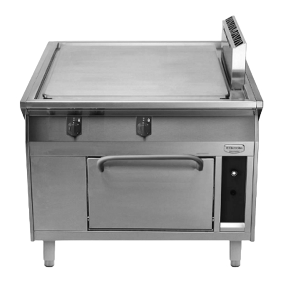
INSTRUCTIONS DE FONCTIONNEMENT III . INSTRUCTIONS DE FONCTIONNEMENT GRANDE ZONE DE CUISSON À GAZ Données générales Une grande zone de cuisson de 840 x 740 mm peut produire une température maximale de 842°F (450°C) au niveau des brûleurs, à une puissance de chauffe de 2 x 7 kW. Le partie inférieure est dotée d'un espace de rangement des produits d'entretien ou d'un four à... - Page 24 INSTRUCTIONS DE FONCTIONNEMENT Nettoyez le sol tout autour de l'appareil selon la méthode traditionnelle, à savoir sans utiliser d'appareil de nettoyage sous pression. N'utilisez en aucun cas de la laine de fer, des spatules ou des brosses métalliques en acier non traité pour nettoyer les surfaces, car les particules de fer susceptibles de s'y déposer pourraient entraîner la formation de rouille.
- Page 25 INSTRUCTIONS DE FONCTIONNEMENT FOUR À GAZ POUR CUIRE ET RÔTIR Le four est intégré dans la partie inférieure de la cuisinière. Le four est équipé de : - coulisses de support des grilles - grille et plat à four La base du four est fermée par une épaisse plaque en acier qui permet de répartir et d'emmagasiner la température inférieure de façon homogène.
- Page 26 INSTRUCTIONS DE FONCTIONNEMENT Démontage : Retirez la plaque de la sole du four (1 / Fig. 13). Soulevez la coulisse de support des grilles (2 / Fig. 13) et extrayez-la de la coulisse (3 / Fig. 13). Montage : Pour le montage, procédez dans le sens inverse. 1 Plaque de la sole du four 2 Coulisses de support...
- Page 27 Table of nozzle - Tableau de gigleur 62.8504.09 ±1% ±1% Pressure after Nominal pres- the pressure Gas type sure with burner regulator with in operation burner in opera- tion inch Water inch Water mbar Gauche Gauche 21 Natural 17.4 gas USA 25 Propane 11.0 27.4...
- Page 28 Table of nozzle - Tableau de gigleur 62.8504.10 ±1% ±1% Pressure after Nominal pres- the pressure Gas type sure with burner regulator with in operation burner in opera- tion inch Water inch Water mbar Gauche Gauche 21 Natural 17.4 gas USA 25 Propane 11.0 27.4...
Need help?
Do you have a question about the Thermaline 584166 and is the answer not in the manual?
Questions and answers