Potterton Heatmax Combi HE Range Installation & Service Instructions Manual
Condensing combination boiler
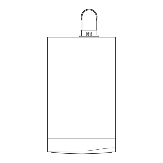
Hide thumbs
Also See for Heatmax Combi HE Range:
Table of Contents

Related Manuals for Potterton Heatmax Combi HE Range


Summary of Contents for Potterton Heatmax Combi HE Range
- Page 1 You can rely on Installation & Service Instructions Heatmax Combi HE Range Condensing Combination Boiler These instructions include the Benchmark Commissioning Checklist and should be left with the user for safe keeping. © Baxi Heating UK Ltd 2012...
-
Page 2: Natural Gas
Natural Gas Building Regulations and the Benchmark Commissioning Checklist Potterton Heatmax Combi 24 HE G.C.N 47-393-27 Building Regulations (England & Wales) require notification of Potterton Heatmax Combi 28 HE the installation of a heating appliance to the relevant Local G.C.N 47-393-28 Potterton Heatmax Combi 33 HE Authority Building Control Department. - Page 3 Installer Notification Guidelines Choose Building Regulations Notification Route Competent Person's Building Control Self Certification Scheme Install and Commission this Contact your relevant Local appliance to manufacturer's Authority Building Control instructions (LABC) who will arrange an inspection or contact a government approved inspector Complete the Benchmark Checklist...
- Page 4 Legislation IMPORTANT - Installation, Commissioning, Service & Repair This company declare that no substances harmful to health are contained in the appliance or used during appliance This appliance must be installed in accordance with the manufacturer’s instructions and manufacture. the regulations in force. Read the instructions fully before installing or using the appliance.
- Page 5 Safe Manual Handling General The following advice should be adhered to, from when first handling the boiler to the final stages of installation, and also during maintenance. Most injuries as a result of inappropriate handling and lifting are to the back, but all other parts of the body are vulnerable, particularly shoulders, arms and hands. Health &...
-
Page 6: Table Of Contents
CONTENTS Section Page Introduction General Layout Appliance Operation Technical Data Dimensions and Fixings System Details Site Requirements Flue Options Plume Displacement 10.0 Installation 11.0 Commissioning 12.0 Completion 13.0 Servicing 14.0 Changing Components 15.0 Setting the Gas Valve 16.0 Electrical 17.0 Short Parts List 18.0 Fault Finding... -
Page 7: Introduction
1.0 Introduction Description 1. The Potterton Heatmax Combi HE is a fully automatic gas fired wall mounted condensing combination boiler. It is room sealed and fan assisted, and will serve central heating and Case Front Panel mains fed domestic hot water. 2. -
Page 8: General Layout
2.0 General Layout Layout Expansion Vessel Automatic Air Vent (Pump) DHW Plate Heat Exchanger / Automatic Bypass Circulation Pump Drain Off Point Pressure Relief Valve Optional Integral Timer Position Central Heating System Pressure Gauge Control Box 3-Way Valve Assembly Condensate Trap Flame Sensing Electrode Spark Electrode Primary Heat Exchanger... -
Page 9: Appliance Operation
3.0 Appliance Operation Central Heating Mode (Fig. 2) Central Heating Circuit 1. With a demand for heating, the pump circulates water through the primary circuit. 2. Once main burner ignites the fan speed controls the gas rate to maintain the heating temperature measured by the temperature sensor. -
Page 10: Technical Data
4.0 Technical Data Heatmax Combi 24, 28 & 33 Appliance Type NO x Class Inlet Pressure (Natural Gas - G20) mbar Appliance Category CAT I Central Heating Primary Circuit Pressures Injector (Natural Gas - G20) Heat Input CH (Net) 7.5mm (24&28 model) 12mm(33 model) 24 model 20.5... -
Page 11: Dimensions And Fixings
5.0 Dimensions and Fixings Dimensions A 780mm At Least 1.5° B 345mm C 450mm D 116mm Ø Min. E 185mm (207mm for 80/125mm flue systems) F 145mm G 131mm H 180mm 360° Orientation ØD Tube Ø 100mm Tap Rail 32.5 mm Condensate Drain 65 mm... -
Page 12: System Details
6.0 System Details Information 1. The Potterton Heatmax Combi HE Condensing Combination IMPORTANT: If the boiler is installed at a high point in Boiler is a ‘Water Byelaws Scheme - Approved Product’. To comply with the Water Byelaws your attention is drawn to the system it is strongly recommended that Automatic the following installation requirements and notes (IRN). - Page 13 6.0 System Details System Filling and Pressurising 1. A filling point connection on the central heating return Double Stop Stop Check pipework must be provided to facilitate initial filling and Valve Valve Valve pressurising and also any subsequent water loss replacement/refilling.
- Page 14 6.0 System Details Domestic Hot Water Circuit (Fig. 7) 1. All DHW circuits, connections, fittings, etc. should be fully in accordance with relevant standards and water supply regulations. Other Tap Outlets 2. Your attention is drawn to: for GB: Guidance G17 to G24 and recommendation R17 to Boiler Expansion R24 of the Water Regulations Guide.
-
Page 15: Site Requirements
7.0 Site Requirements 5mm Min 450mm 5mm Min Location 1. The boiler may be fitted to any suitable wall with the flue 200mm Min passing through an outside wall or roof and discharging to (300mm Min if using 80/125mm atmosphere in a position permitting satisfactory removal of flueing system) combustion products and providing an adequate air supply. - Page 16 7.0 Site Requirement Ventilation of Compartments 1. Where the appliance is installed in a cupboard or compartment, no air vents are required. 2. BS 5440: Part 2 refers to room sealed appliances installed in compartments. The appliance will run sufficiently cool without ventilation.
- Page 17 Examples are shown of the following methods of termination:- 7.0 Site Requirements i) to an internal soil & vent pipe ii) via an internal discharge branch (e.g. sink waste) downstream of the trap iii) to a drain or gully iv) to a purpose made soakaway Condensate Drain v) pumped into an internal discharge branch (e.g.
- Page 18 7.0 Site Requirements Condensate Drain (cont.) iii) Termination to a drain or gully 11. When discharging condensate into a soil stack or waste Boiler pipe the effects of existing plumbing must be considered. If soil pipes or waste pipes are subjected to internal pressure Pipe must terminate above fluctuations when WC's are flushed or sinks emptied then water level but below...
- Page 19 v) pumped into an internal discharge branch 7.0 Site Requirements (e.g. sink waste) downstream of the trap Pipe must terminate above Sink Condensate Drain (cont.) water level but below surrounding surface. Cut end at 45° 12. A boiler discharge pump is available, ‘MULTIFIT’ part no.
- Page 20 Terminal Position with Minimum Distance (Fig. 18) (mm) 7.0 Site Requirements Directly below an opening, air brick, opening windows, etc. Above an opening, air brick, opening window etc. Horizontally to an opening, air brick, opening window etc. Flue Below gutters, soil pipes or drain pipes. 25 (75) Below eaves.
-
Page 21: Flue Options
8.0 Flue Options Horizontal Flue Systems 1. The standard flue is suitable only for horizontal termination applications. 2. All fittings should be fully engaged. The approximate engagement is 40mm. Apply soap solution to the seal on each fitting to aid assembly. 3. - Page 22 8.0 Flue Options Vertical Flue Systems Vertical Flues 1. Maximum permissible equivalent flue lengths are:- (60/100) (80/125) Vertical Concentric 10 metres 20 metres 2. Any additional “in line” bends in the flue system must be taken into consideration. Their equivalent lengths are:- Concentric Pipes: 135°...
- Page 23 8.0 Flue Options Flue Accessories Accessory Size Code No FLUE GROUP A Concentric Flue System 100mm diameter Horizontal Flue Terminal (inc. elbow) 5118489 Telescopic Flue (inc. elbow) 315-500mm 5118069 Telescopic Internal Flue Kit 315-500mm 5119654 Flue Extension 1000mm 5111074 Flue Bend 93°...
- Page 24 8.0 Flue Options For Roof Terminals 1. In the case of a pitched roof 25 - 50 degrees, position the lead Approx tile to replace/flash over existing roof tiling. Make an aperture in 1425mm the roof suitable for the lower tube of the roof terminal and ensure the integrity of the roof cover is maintained.
-
Page 25: Plume Displacement
93° Elbow/Plume 9.0 Plume Displacement Outlet Assembly 9 .1 Plume Displacement Kit (Fig. 23) 60Ø Support O Ring Bracket Kit No 5118638 Content of kit 0.9 metres 0.9m 60/100 Concentric Flue 1m 60 Dia Exhaust Flue Pipe 60Ø Exhaust Adaptor Flue Pipe 60 Dia Support Brackets 93°... - Page 26 9.0 Plume Displacement Determining Permissible Lengths In the graph the solid line diagonal represents the relationship between the concentric flue assembly (and any extensions) and the 60Ø exhaust (and any extensions or additional bends). Example 1 - Not Permissible If, for instance, a concentric length of 5 metres was required and the 60Ø...
- Page 27 9.0 Plume Displacement General Fitting Notes 1. Cut a hole in the external wall which the concentric flue assembly will pass through. The hole should allow the flue to fall back to the boiler at an angle of at least 1.5°. 2.
- Page 28 9.0 Plume Displacement Plume Outlet Elbow General Fitting Notes (cont.) 15. For aesthetic purposes it is permissible to route the 60Ø exhaust in an enclosed box, but the air inlet and plume outlet MUST remain in free air. 16. It is also possible to separate the plume outlet from the 93°...
-
Page 29: Installation
10.0 Installation 10.1 Unpacking & Initial Preparation The gas supply, gas type and pressure must be checked for suitability before connection (see Section 7.4). NOTE: a small amount of water may drain from the boiler in the upright position. Fig. 39 1. - Page 30 10.0 Installation Wall Plate 10.3 Fitting The Boiler 1. Remove the sealing caps from the boiler connections. NOTE: A small amount of water may drain from the boiler once the caps are removed. Sealing Washers 2. Lift the boiler as indicated by the shaded areas. The boiler should be lifted by TWO PEOPLE.
- Page 31 10.0 Installation 10.6 Fitting The Flue HORIZONTAL FLUE 1. The standard flue is suitable for lengths between 100mm Fig. 45 minimum and 685mm maximum, as measured from the edge of the flue elbow outlet to the joint between the terminal and air duct (Fig. 45). 2.
- Page 32 10.0 Installation Inner Flue Support Bracket 10.6 Fitting the Flue (Cont) 6. The inner flue duct support bracket may be in the waste portion of the flue. In this case retrieve the bracket before discarding the waste. 7. Take the inner flue support bracket (if not already fitted) Fig.
- Page 33 10.0 Installation 10.7 Making The Electrical Connections NOTE: Both the Live and Neutral connections are fused. To connect an external control proceed as follows:- 1. Slacken the facia panel securing screws and lift the outercase panel so that its securing tabs are clear of the facia.
-
Page 34: Commissioning
11.0 Commissioning 11.1 Commissioning the Boiler 1. Reference should be made to BS:EN 12828 & 14336 when commissioning the boiler. 2. At the time of commissioning, complete all relevant sections of the Benchmark Checklist at the rear of this publications. Screw 3. - Page 35 11.0 Commissioning 11.2 Check the Operational (Working) Gas Inlet Pressure 1. Ensure that all controls are calling for heat, and the selector switch is in the central heating and hot water position ( The current boiler temperature is shown on the display. Central Heating Domestic Hot Water Temperature Control...
-
Page 36: Completion
12.0 Completion 12.1 Completion Case Front Panel 1. Instruct the user in the operation of the boiler and system explaining the operational sequence. 2. Set the central heating and hot water temperature control knobs to the requirements of the user. 3. -
Page 37: Servicing
13.0 Servicing 13 .1 Annual Servicing 1. For reasons of safety and economy, it is recommended that Case Front Panel the boiler is serviced annually. Servicing must be performed by a competent person in accordance with B.S. 7967-4. 2. After servicing, complete the relevant Service Interval Record section of the Benchmark Commissioning Checklist at the rear of this publication. - Page 38 13.0 Servicing 13.2 Annual Servicing - Inspection (Cont) 6. Undo the nut on the gas inlet pipe to the venturi (Fig. 73) and pull the sensing pipe off the fan. 7. Disconnect the electrode leads, noting their position, and Sensing the fan electrical plugs.
-
Page 39: Changing Components
14.0 Changing Components IMPORTANT: When changing components ensure that Bracket both the gas and electrical supplies to the boiler are isolated before any work is started. When the component has been changed turn the selector switch Igniter fully anticlockwise against the spring pressure to the reset position and hold for 5 seconds to reset the boiler Igniter Feed before recommissioning. - Page 40 14.0 Changing Components 14.3 Fan (Fig. 79) 1. Undo the nut on the gas inlet pipe to the venturi (Fig. 79) and pull the sensing pipe off the fan. 2. Disconnect the electrode leads, noting their position and disconnect the fan electrical plugs. 3.
- Page 41 14.0 Changing Components Cover 14.6 Burner (Fig. 81) Burner 1. Undo the screws securing the collector to the cover and Gasket venturi. On 24/28 models there is an extension piece fitted to the cover - remove this also. Extension Piece (not on 33 models) 2.
- Page 42 14.0 Changing Components Electrical Plug 14.8 Flue/Heat Exchanger Thermostat Sensor Flue/Heat Exchanger (Fig. 83) Thermostat Sensor 1. Ease the retaining tab on the sensor away and disconnect the electrical plug. 2. Turn the sensor 90 anticlockwise to remove - it is a °...
- Page 43 14.0 Changing Components 14.14 Pump - Head Only (Fig. 87) 1. Drain the boiler primary circuit and remove the socket head screws securing the pump head to the body and draw the head away. 2. Undo the screw on the pump wiring cover and remove the cover.
- Page 44 14.0 Changing Components 14.17 Pressure Gauge (Figs. 90 & 91) Gauge Retaining Bracket 1. Drain the boiler primary circuit and undo the nut on the pressure gauge capillary. 2. Undo the screws securing the gauge retaining bracket. 3. Remove the bracket and gauge assembly. Depress the barbs on the side of the gauge and remove the retaining bracket.
- Page 45 14.0 Changing Components 14.20 Plate Heat Exchanger (Fig. 94) 1. Drain the boiler primary circuit and remove the gas valve Plate Heat Exchanger as described in section 14.24. 2. While supporting the heat exchanger undo the screws securing it to the brass manifolds. 3.
- Page 46 14.0 Changing Components 14.22 P.C.B. (Fig. 98) 1. Note the settings of the temperature control knobs, rotate them fully anticlockwise and carefully pull them off the drive pins. 2. Completely undo the screws securing the control box cover and release the cover retaining barbs from their slots. Disengage the rear of the cover from the control box hinge pin (Fig.
- Page 47 14.0 Changing Components Venturi Inlet Pipe 14.24 Gas Valve (Fig. 99) IMPORTANT: After replacing the valve the CO must be Gas Valve checked and adjusted as detailed in Section 15.0 Setting the Gas Valve. Only change the valve if a suitable calibrated combustion analyser is available, operated by a competent person - see section 13.1.
-
Page 48: Setting The Gas Valve
15.0 Setting the Gas Valve 15.1 Setting the Gas Valve ( check) IMPORTANT: The CO must be only be checked and adjusted to set the valve if a suitable calibrated combustion analyser is available, operated by a competent person - see Section 13.1 Central Heating Domestic Hot Water Temperature Control... -
Page 49: Electrical
16.0 Electrical 16.1 Illustrated Wiring Diagram Central Heating NTC Sensor NTC Sensor Overheat Stat Hall Effect Sensor Water Pressure Flue Sensor Switch X400 X401 9 8 7 6 5 4 3 2 1 8 7 6 5 4 3 2 1 Optional Timer Control PCB X501... -
Page 50: Short Parts List
17.0 Short Parts List Short Parts List G.C. Description Manufacturers Part No. 5121447 Motor 3way Valve 5132452 Igniter Electrode 720222801 Sensing Electrode 5114703 Gas Valve 720301001 Hall Effect Sensor 5114767 Burner 24/28 5122149 Burner 33 5114697 Flue Sensor 720851401 Water Pressure Switch 5114748 Plate Heat Exchanger 24 248048... -
Page 51: Fault Finding
18.0 Fault Finding 18.1 Initial Fault Finding Checks NOTE: When instructed to turn the 1. Check that gas, water and electrical supplies are available selector to the reset position turn the at the boiler. selector switch fully anticlockwise against the spring pressure to the reset position 2. - Page 52 18.0 Fault Finding Refer to Section 16.0 “Illustrated Wiring Diagram” for position of terminals and components Central Heating - Follow operational sequence Turn selector switch to Go to section ‘A’ The display illuminates Error 110 flashing If the error 110 is still flashing. Turn the selector switch to Error 130 flashing reset position for 5 seconds...
- Page 53 18.0 Fault Finding Domestic Hot Water - Follow operational sequence Turn selector switch to Go to section ‘A’ The display illuminates Error 110 flashing Turn the selector switch to If the error 110 is still flashing. Error 133 flashing Go to section ‘J’ reset position for 5 seconds Error 20, 28 or 50 flashing Go to section ‘E’...
- Page 54 18.0 Fault Finding Fault Finding Solutions Sections Is there 230V at: Main terminals L and N Check electrical supply Main terminal fuse Replace fuse Display Replace PCB illuminated Check wiring PCB - X1 connector terminals 1,2 Is there 230V at: Pump If pump jammed, release Replace pump...
- Page 55 18.0 Fault Finding E20 or E50 - Temperature sensors faulty. Cold resistance approximately @ 25° C (DHW and CH sensors) Replace sensor or PCB (E28) @ 25° C (Flue sensor) (resistance reduces with increase in temp.) E28 - Incorrect PCB fitted Check and correct the connection of the tube between the venturi and gas valve Gas at burner...
- Page 56 18.0 Fault Finding Check supply pressure at the gas valve:- Minimum 17mbar Check and correct if necessary 1. The mechanical set of the gas valve (CO2 values - see instruction) 2. Flame sensing electrode and lead connections 3. Flame sensing electrode position Replace PCB Flame current should be more than 0.5 Replace flame sensing electrode...
-
Page 57: Pages For Notes
19.0 Notes... -
Page 58: Benchmark Checklist
GAS BOILER SYSTEM COMMISSIONING CHECKLIST This Commissioning Checklist is to be completed in full by the competent person who commissioned the boiler as a means of demonstrating compliance with the appropriate Building Regulations and then handed to the customer to keep for future reference. Failure to install and commission according to the manufacturer’s instructions and complete this Benchmark Commissioning Checklist will invalidate the warranty. -
Page 59: Service Record
Service Record It is recommended that your heating system is serviced regularly and that the appropriate Service Interval Record is completed. Service Provider Before completing the appropriate Service Record below, please ensure you have carried out the service as described in the manufacturer’s instructions. - Page 60 All descriptions and illustrations provided in this leaflet have been carefully prepared but we reserve the right to make changes and improvements in our products which may affect the accuracy of the information contained in this leaflet. All goods are sold subject to our standard Conditions of Sale which are available on request.