Table of Contents
Advertisement
Advertisement
Table of Contents

Related Manuals for Sonic Frontiers THE SONIC FRONTIERS LINE SERIES


Summary of Contents for Sonic Frontiers THE SONIC FRONTIERS LINE SERIES
- Page 1 T H E S O N I C F R O N T I E R S L I N E S E R I E S P R E A M P L I F I E R S O W N E R ’...
-
Page 2: Table Of Contents
OPERATING MANUAL FOR THE SONIC FRONTIERS LINE SERIES PREAMPLIFIERS We at Sonic Frontiers hope you will derive many years of listening pleasure with your new LINE Series Preamplifier. This Operating Manual contains important information regarding the operation and care of these Preamplifiers. Be sure to read this manual carefully and fol- low these instructions in order to keep them performing and sounding their best. -
Page 3: Unpacking
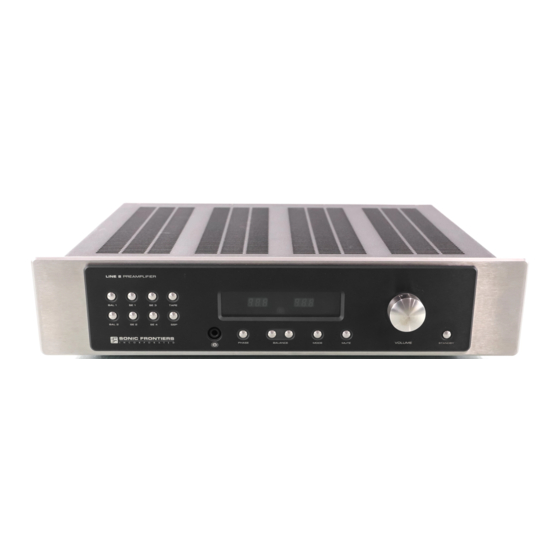
U N P A C K I N G At this point we assume that you have successfully opened the box flaps and found this manual. These boxes were designed to ensure the safe transport of the LINE Series Preamplifiers. Sonic Frontiers strongly recommends the storage of these boxes in a safe dry place. - Page 4 OP E RA T ION, C O NNE CT I ON S AN D C ON TRO L F U NC TI O NS 1, L RONT ANEL Note: This diagram applies to ALL LINE Series preamplifiers, as they all have identical front panel functions. Figure 1 - Line 1, Line 2, and Line 3 Front Panel ANEL Figure 2 - Line 1 Rear Panel...
- Page 5 O PER A TI O N, CO NN E CT IO NS AN D CO NT R OL FUNC T I ON S C ON T’ D OWER UPPLY EAR AND RONT ANELS Figure 4 - Line 2 Power Supply Rear and Front Panels OWER UPPLY RONT...
-
Page 6: Control And Connection Functions
CONTR OL AND CONNE CTION FUNCTIO NS A - X L R Balanced Input Buttons (BAL 1, BAL 2) - ly and safely. Depending upon the methods used in These buttons will select a balanced input signal connected producing the recording, the user may prefer listening to a to one of the XLR Balanced Inputs. - Page 7 C ONNECTION S A ND CONT ROL F UNC TIONS C O N T ’ D To store a volume/balance setting, adjust the volume and bal- Preamplifiers, the left channel is situated on the upper row of ance to the desired level then press and hold the button corre- connectors and the right channel is on the lower row.
-
Page 8: Preamplifier Set-Up
P RE A MPL IF IE R S ET -U P You are now ready to begin setting up your preamplifier. INSERTION OF THE TUBES W A R N I N G DISCONNECT the AC Detachable Power Cord from the Line 1 Main Chassis or Line 2 & Line 3 Power Supply before removing the Preamplifier chassis cover. -
Page 9: Chassis Placement
PREAMPLIFIER SET-UP CONT’D 5 . Take the LV1 tube and inspect the pins noting the large space The units must be placed on a hard flat surface (N O T on carpet), between two of the pins. This space will align with the same larg- preferably side by side or on separate shelves with plenty of er space between two of the pin holes on the socket. -
Page 10: Power Connections
PREAMPLIFIER SET-UP CONT’D POWER CONNECTIONS HOME THEATRE ACCESSORIES (OPTIONAL) Once all input and output signal connections are made, you can There are two external connections provided for customization of begin to make the power connections. you home theatre set-up. These are the I.R Jack (Infra Red) and the Relay Trigger. -
Page 11: Powering On And Startup Procedures
POWERING ON & STARTUP PROCEDURES Do not attempt to turn on your preamplifier until ALL prior steps 4. When you have selected your desired input (BAL 1, BAL 2, or have been completed. SE1-SE4) you can change the phase polarity from 0˚ to 180˚, change the mode from STEREO to MONO, MUTE the output, 1. -
Page 12: Remote Control Functions
R EM OT E CO NT R O L FUN CT I ON S 1 - Dual Infra Red Emitters - These emitters transmit the coded data from 8 - Mute - The preamp can be muted by pressing the mute button. When the the remote control to the LINE Series main chassis front panel. - Page 13 MO D E F UN CTI O N When the MODE button is depressed the STEREO inputs from both the left and right channel are combined or blended to MONO operation. This gives a reduction in “separation” from approximately 100dB down to approximately 8dB between STEREO channels and is desirable for reducing apparent separa- tion between stereo speakers, or for establishing the the proper spacial effect for more natural reproduction using stereo head-...
-
Page 14: Trouble Shooting
TROUBLE SHOOTING If the LINE Series Preamplifier is not functioning properly, please check each of the following: W A R N I N G Fuse D I S C O N N E C T the AC Detachable Power Cord from the Line 1 Main Chassis or Line 2 &... -
Page 15: Safety Instructions
SAFETY INSTRUCTIONS 1. Ventilation - Although your LINE Series Preamplifier generates LIMITED FIVE YEAR WARRANTY only nominal heat in use, be sure that the ventilation slots in the Sonic Frontiers, Inc. warrants to the purchaser that each Line top cover have at least 6” of unobstructed air space above them. Series Preamplifier and Power Supply is free of manufacturing Do Not obstruct the bottom vent by operating the preamplifier on defects for a period of five (5) years from the date of purchase. -
Page 16: Technical Specifications
T EC H NI CAL S PE C IF I CAT I ON S LINE 1 T EC HN I CAL SPE CI FI CAT IO NS LI NE 2 T EC HN I CAL SPE CI FI CAT IO NS Frequency Response 2 Hz to 250 kHz -0.5 dB Frequency Response... -
Page 17: Remote Control Battery Replacement
TEC HNI C A L SP EC I FIC A TI O NS C O N T ’ D LI N E 3 TE CH NIC AL SP EC IFIC ATI ON S REMO TE C ONTRO L TEC HN ICA L S P E C I F I C A T I O N S Frequency Response 2 Hz to 250 kHz +/- 0.5 dB... - Page 18 We at Sonic Frontiers are sure that you will derive many years of listening pleasure with your new LINE Series Preamplifier and Power Supply. This Owner’s Manual contains important informa- tion regarding the operation and care of the LINE Series Preamplifiers.
Need help?
Do you have a question about the THE SONIC FRONTIERS LINE SERIES and is the answer not in the manual?
Questions and answers