Table of Contents
Advertisement
Advertisement
Table of Contents

Summary of Contents for Sonic Frontiers Sonic Frontiers PHONO 1
- Page 1 S O N I C PHONO 1 PHONO STA G E F R O N T I E R S O P E R ATING MANUAL...
- Page 2 We at Sonic Frontiers are sure that you will derive many years of listening pleasure with your new PHONO 1 Phono Stage. This Owner’s Manual contains important information regarding the operation and care of the PHONO 1 Phono Stage. Be sure to read this manual carefully and follow these instructions in order to keep it looking, operating and sounding its best.
-
Page 3: Table Of Contents
OPERATING MANUAL FOR THE SONIC FRONTIERS PHONO 1 PHONO STAGE We at Sonic Frontiers hope you will derive many years of listening pleasure from your new . This Operating Manual contains important information regarding PHONO 1 Phono Stage the operation and care of this Phono Stage. Be sure to read this manual carefully and follow these instructions in order to keep it performing and sounding its best. -
Page 4: Unpacking
U N P A C K I N G At this point we assume that you have successfully opened the box flaps and found this manual. This box was designed to ensure the safe transport of your PHONO 1 Phono Stage. Sonic Frontiers strongly recommends the storage of this box in a safe dry place. -
Page 5: Operation, Connection And Control Diagrams
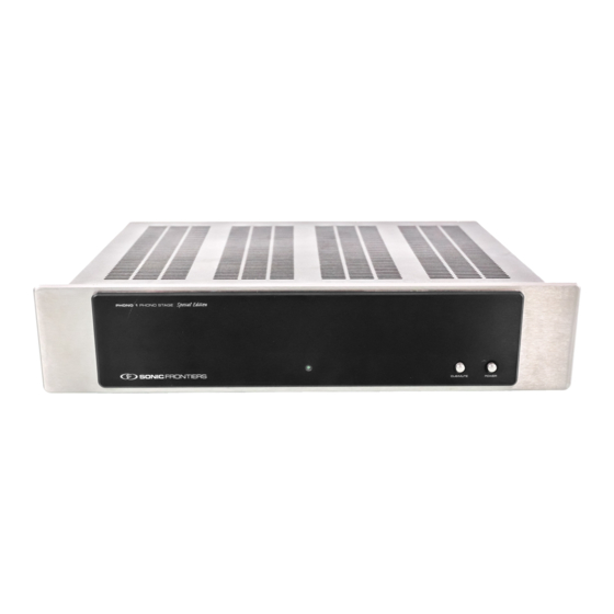
O PER A TI ON , C ON NEC T IO NS AN D CO NT R OL FU N CT I ON S HONO RONT ANEL Figure 1 - PHONO 1 Front Panel HONO ANEL Figure 2 - PHONO 1 Rear Panel... -
Page 6: Control And Connection Functions
C ONTROL AN D CONNE CTIO N FU NCTI ONS FRONT PANEL REAR PANEL A - Front Panel LED Indicator - When the Power Switch D - Detachable Power Cord Socket - Plug the supplied (C) is pushed to the “ON” position (IN) this LED will light. power cord (female) end into this inlet, and after checking that the power switch (C) is in the out position, plug the other B - Cue/Mute Button - Pushing this switch in will attenuate or... -
Page 7: Phono Stage Set-Up
P HON O ST A GE S ET -U P You are now ready to begin setting up your phono stage. N o t e : Partially install the screws, then go back and tighten them all. Do not over-tighten. 7 . -
Page 8: Connecting External Equipment
PHONO STAGE SET-UP CONT’D CONNECTING EXTERNAL EQUIPMENT & EXTERNAL ADJUSTMENTS Connect the turntable to the Phono 1 input RCA jacks (F) and To select a loading value, it is necessary to refer to the position using a suitable length of interconnect cable, connect the number on the loading switch(s), (G). -
Page 9: Power Connections
POWERING ON & STARTUP PROCEDURES POWER CONNECTIONS SHUTTING OFF POWER Once all input and output signal connections are made, you can begin to make the power connections. W A R N I N G Always turn “off” your power amplifier and/or line level preamp first, before turning off the PHONO STAGE POWER CONNECTIONS phono stage. -
Page 10: Trouble Shooting
TROUBLE SHOOTING If the PHONO 1 Phono Stage is not functioning properly, please check each of the following: Fuse W A R N I N G D I S C O N N E C T the AC Detachable Power Cord from t he Phono 1 bef or e beginni ng t r o u b l e s h o o t i n g . -
Page 11: Safety Instructions
SAFETY INSTRUCTIONS 1. Ventilation - Although your PHONO 1 Phono Stage generates LIMITED FIVE YEAR WARRANTY only nominal heat in use, be sure that the ventilation slots in the Sonic Frontiers, Inc. warrants to the purchaser that each PHONO top cover have at least 6” of unobstructed air space above them. 1 is free of manufacturing defects for a period of five (5) years Do Not obstruct the bottom vent by operating the phono stager from the date of purchase. -
Page 12: Technical Overview
TE CH NI C AL O VE RV I EW The Sonic Frontiers Phono 1 is a single chassis phono stage with an network is used, and this is fed from a relatively low impedance, equalized gain of 62dB at 1kHz. The circuit topology is non-invert- thereby avoiding slew limiting at high frequencies, with its attendant ing, and uses a single high quality J-Fet for the input amplifier, and a d i s t o r t i o n s .


Need help?
Do you have a question about the Sonic Frontiers PHONO 1 and is the answer not in the manual?
Questions and answers