Table of Contents
Advertisement
Advertisement
Table of Contents

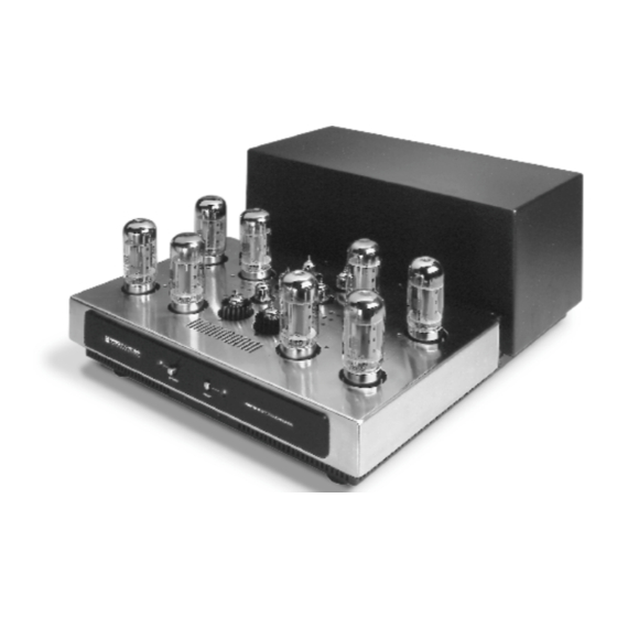
Summary of Contents for Sonic Frontiers Power 2
- Page 1 Operating Manual for the Sonic Frontiers Power 2 Stereo Amplifier...
-
Page 2: Table Of Contents
We at Sonic Frontiers hope you will derive many years of listening pleasure with your new Power 2 Amplifier. This Operating Manual contains important information regard- ing the operation and care of this Amplifier. Be sure to read this manual carefully and follow these instructions in order to keep them performing and sounding their best. -
Page 3: Unpacking
The box was designed to ensure the safe transport of the amplifier, Sonic Frontiers strongly recommends the storage of the Power 2 box in a safe, dry place. In the event that the amplifier may have to be shipped in the future, the original box is the best means for the protection and safety of the Power 2 during transportation. -
Page 4: Quick Setup
(carpeting or area rugs are NOT acceptable as hard surfaces). 2. Ensure the Power 2 is in Mute mode (these selector switches are on the rear of the chassis). When disconnecting and connecting cable, placing the amplifier in Mute is an excellent practice. -
Page 5: Reference Diagrams
Reference Diagrams Tube locations V1 to V3 and LV1 to LV3 indicate placement for the six 6922 tubes. Tube locations V4 and LV4 indicate placement for the two 5687 tubes. Locations V5 to V8 and LV5 to LV8 indicate placement for the 6550C/KT88 power tubes. Holes on the Tube Top labeled “A”... - Page 6 This drawing is referred to as the “Front Panel” within the instructional text. This drawing is referred to as the “Rear Panel” within the instructional text. Power Switch Standby Switch Power LED (Green - Power; Red - Mute; Orange (Red + Green) - One Channel in Mute) Standby LED (Green - Operate;...
-
Page 7: Installing The Tubes
DAMAGE TO THE TUBE, AMPLIFIER (OR BOTH) THAT WOULD NOT BE COVERED UNDER WARRANTY. The 5687 tube is designed to run very hot. In its implementation in the Power 2, it is being used at 1/3 its ratings. Even at this rating, the 5687 still gets hot and therefore, the 2 P e a r l Tu b e coolers should be installed over the 5687 tubes. - Page 8 When installing the 6550C or KT88 power tubes, match the numbers designated on the metal base of the tube or the tube boxes to the corresponding markings printed on the tube top (V5 through V8 and LV5 through LV8) and be sure the center pin key locator is in alignment with the slot in the center of the socket.
-
Page 9: Biasing Of The Power Tubes
A cutaway of the tube top showing the location of the biasing controls below the tube top surface and the biasing driver. Biasing of the Power Tubes Bias voltage applied to the grids of the power tubes in the output stage should be checked from time to time (once a month) to keep these tubes operating at the optimum operating point. -
Page 10: Front Panel
Rear Panel Refer to Reference Diagrams. G Detachable Power Plug the detachable Power Cord into this socket. The Power 2 amplifier is configured Cord Socket for the operating voltages in which they are sold. See shipping box or Voltage/ Impedance sticker on rear of the chassis for voltage settings. If a different operating voltage is required, please contact an authorized Sonic Frontiers dealer or the factory directly. - Page 11 180°out of phase relative to the original signal and correction for this configura- Inverting Inputs tion is desired. The input on the Power 2 does invert the phase of the output signal, rela- tive to the input signal. Connections should be made left channel to left channel right channel to right.
-
Page 12: Adjustment For Load Impedance
Adjustment for Load Impedance Note: Adjustment for load impedance should only be done by an authorized Sonic Frontiers dealer, distributor or service technician. Any damage to the amplifier as a result of a person(s) not authorized by Sonic Frontiers will not be covered under warranty. Warning: Dangerous voltages exist within this amplifier. - Page 13 Note the solder connections on the terminal block. Under no circumstances should these connections be tampered with. 4.Using the slot screwdriver provided with the amp, deal with one connection at a time, loosening off the tap screws of the first spade lug connection and tightening to the desired tap.
-
Page 14: Care And Maintenance
Power 2 to allow for free movement of air for proper cooling. If the amplifier is to be placed on a carpeted floor, a Wood, Ceramic, Concrete, Marble... tile or slab 18”... -
Page 15: Troubleshooting
Sonic Frontiers dealer or Sonic Frontiers directly. Break-in Time As with all audio electronic products, the ultimate sonic character of the Power 2 will not be realized until and unless the unit receives a minimum of approximately 70 hours of signal break-in time (i.e. -
Page 16: Limited Five Year Warranty
Warranty Disclaimer of Liability Under no circumstances does Sonic Frontiers, Inc. assume liability or responsibility for injury or damages sustained in the use or operation of this equipment or for damages to any other equipment connected to it. Sonic Frontiers, Inc. reserves the right to make design changes or improvements without the obligation to revise prior versions. -
Page 17: Specifications
Specifications Note: Power ratings based on a nominal power line input. All specifications are made on the 8 ohm taps, utilizing an 8 ohm load unless otherwise specified. Power Output: 110 watts continuous at 8, 4 and 2 ohms from 20 Hz to 20 kHz with less than 1% total harmonic distortion terminated with rated load (typically <0.5% @ 110 watts 1 kHz) both channels driven.


Need help?
Do you have a question about the Power 2 and is the answer not in the manual?
Questions and answers