Table of Contents
Advertisement
Advertisement
Table of Contents

Subscribe to Our Youtube Channel
Related Manuals for ECS X58B-A2


Summary of Contents for ECS X58B-A2
- Page 3 Preface Copyright This publication, including all photographs, illustrations and software, is protected under international copyright laws, with all rights reserved. Neither this manual, nor any of the material contained herein, may be reproduced without written consent of the author. Version 1.0 Disclaimer The information in this document is subject to change without notice.
-
Page 4: Declaration Of Conformity
Declaration of Conformity This device complies with part 15 of the FCC rules. Operation is subject to the following conditions: • This device may not cause harmful interference, and • This device must accept any interference received, including interfer- ence that may cause undesired operation Canadian Department of Communications This class B digital apparatus meets all requirements of the Canadian Interference- causing Equipment Regulations. -
Page 5: Table Of Contents
T T T T T ABLE OF CONTENTS ABLE OF CONTENTS ABLE OF CONTENTS ABLE OF CONTENTS ABLE OF CONTENTS Preface Chapter 1 Introducing the Motherboard Introduction...................1 Feature....................2 Specifications................4 Motherboard Components............5 7 7 7 7 7 Chapter 2 Installing the Motherboard Safety Precautions................7 Choosing a Computer Case.............7 Installing the Motherboard in a Case..........7... - Page 6 PC Health Status..............37 M.I.B (MB Intelligent BIOS)..........39 Load Default Settings............42 Supervisor Password............42 User Password..............43 Save & Exit Setup..............43 Exit Without Saving...............43 Updating the BIOS..............44 45 45 45 45 Chapter 4 Using the Motherboard Software About the Software CD-ROM............45 Auto-installing under Windows XP/Vista........45 Running Setup...............46 Manual Installation................50 Utility Software Reference............50...
-
Page 7: Introducing The Motherboard
Chapter 1 Introducing the Motherboard Introduction Thank you for choosing the X58B-A2 motherboard. This motherboard is a high performance, enhanced function motherboard designed to support the LGA1366 ® socket Intel Core i7 processor for high-end business or personal desktop markets. The motherboard incorporates the Intel X58 Northbridge (NB) and Intel ICH10R ®... -
Page 8: Feature
Feature Processor ® The motherboard uses an LGA1366 type of Intel Core i7 processor that carries the following features: ® • Accommodates Intel Core i7 processor • Intel ® QuickPath Interconnect (Intel ® QPI) of 4.8 GT/s to 6.4 GT/s support- ing different routing lengths Chipset The X58 Northbridge (NB) and ICH10R Southbridge (SB) chipsets are based on... -
Page 9: Bios Firmware
• CPU parameters • CPU and memory timing • ECS M.I.B. BIOS The firmware can also be used to set parameters for different processor clock speeds. 1. Some hardware specifications and software items are subject to change without prior notice. -
Page 10: Specifications
Specifications • LGA1366 socket for latest Intel ® Core i7 processor ® ® • Intel QuickPath Interconnect (Intel QPI) of 4.8 GT/s to 6.4 GT/s supporting different routing lengths Chipset • Intel X58 & ICH10R • North Bridge: Intel X58 •... -
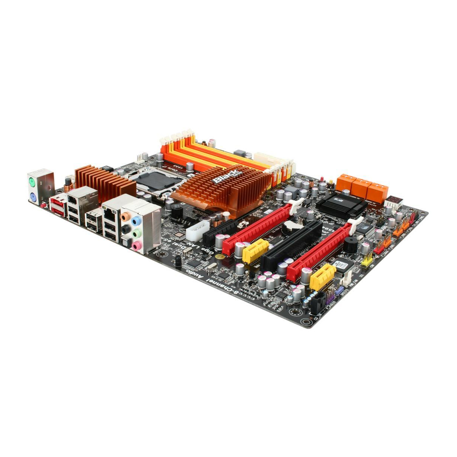
Page 11: Motherboard Components
Motherboard Components Table of Motherboard Components LABEL COMPONENTS ® 1. CPU Socket LGA1366 socket for Intel Core i7 processor 2. CPU_FAN CPU cooling fan connector 3. DDR3_1~6 240-pin DDR3 SDRAM slots 4. ATX_POWER Standard 24-pin ATX power connector Power on button 5. - Page 12 Memo Introducing the Motherboard...
-
Page 13: Installing The Motherboard
Chapter 2 Installing the Motherboard Safety Precautions • Follow these safety precautions when installing the motherboard • Wear a grounding strap attached to a grounded device to avoid dam- age from static electricity • Discharge static electricity by touching the metal case of a safely grounded object before working on the motherboard •... -
Page 14: Checking Jumper Settings
Do not over-tighten the screws as this can stress the motherboard. Checking Jumper Settings This section explains how to set jumpers for correct configuration of the motherboard. Setting Jumpers Use the motherboard jumpers to set system configuration options. Jumpers with more than one pin are numbered. -
Page 15: Checking Jumper Settings
Checking Jumper Settings The following illustration shows the location of the motherboard jumpers. Pin 1 is labeled. Jumper Settings Type Jumper Description Setting (default) 1-2: NORMAL 2-3: CLEAR CMOS CLR_CMOS 3-pin Clear CMOS Before clearing the CLR_CMOS CMOS, make sure to turn off the system. -
Page 16: Installing Hardware
Installing Hardware Installing the Processor Caution: When installing a CPU heatsink and cooling fan make sure that you DO NOT scratch the motherboard or any of the surface-mount resis- tors with the clip of the cooling fan. If the clip of the cooling fan scrapes across the motherboard, you may cause serious damage to the motherboard or its components. -
Page 17: Cpu Installation Procedure
CPU Installation Procedure The following illustration shows CPU installation components. A. Opening of the Load Plate · Put your thumb on the tail of the load plate and press the tail down. · Rotate the load plate to fully open position. -
Page 18: Installing Memory Modules
1. To achieve better airflow rates and heat dissipation, we suggest that you use a high quality fan with 3800 rpm at least. CPU fan and heatsink installation procedures may vary with the type of CPU fan/ heatsink supplied. The form and size of fan/heatsink may also vary. 2. -
Page 19: Installation Procedure
1. For best performance and compatibility, we recommend that users give priority to the yellow DIMMs (DDR3_2/DDR3_4/DDR3_6) when installing DIMMs. 2. We suggest users not mix memory type. It is recommended to use the same brand and type memory on this motherboard. Do not remove any memory module from its antistatic packaging until you are ready to install it on the motherboard. - Page 20 Table A: DDR3 (memory module) QVL (Qualified Vendor List) The following DDR3 1333/1066/800 memory modules have been tested and qualified for use with this motherboard. Type Size Vendor Module Nam e DDR3 800 HYNIX PC3-6400U-6-00 1 GB A-data M3OSS3H3I3120B5Z/Boxed Aeneon AEH760UD00-10FA98X Corsair CM3X1024-1066C7/Boxed...
-
Page 21: Expansion Slots
Expansion Slots Installing Add-on Cards The slots on this motherboard are designed to hold expansion cards and connect them to the system bus. Expansion slots are a means of adding or enhancing the motherboard’s features and capabilities. With these efficient facilities, you can in- crease the motherboard’s capabilities by adding hardware that performs tasks that are not part of the basic system. - Page 22 Follow these instructions to install an add-on card: Remove a blanking plate from the system case corresponding to the slot you are going to use. Install the edge connector of the add-on card into the expansion slot. Ensure that the edge connector is correctly seated in the slot. Secure the metal bracket of the card to the system case with a screw.
-
Page 23: Connecting Optional Devices
Connecting Optional Devices Refer to the following for information on connecting the motherboard’s optional devices: F_AUDIO: Front Panel Audio header This header allows the user to install auxiliary front-oriented microphone and line- out ports for easier access. Signal Name Signal Name PORT 1L AUD_GND PORT 1R... -
Page 24: F_Usb1~3: Front Panel Usb Headers
F_USB1~3: Front Panel USB headers The motherboard has six USB ports installed on the rear edge I/O port array. Addi- tionally, some computer cases have USB ports at the front of the case. If you have this kind of case, use auxiliary USB connector to connect the front-mounted ports to the motherboard. - Page 25 COM: Onboard serial port header Connect a serial port extension bracket to this header to add a second serial port to your system. Signal Name Function DCDB Data carry detect NSINB Serial Data In NSOUTB Serial Data Out DTRB Data terminal ready Ground DSRB Date set ready...
-
Page 26: Installing A Hard Disk Drive/Cd-Rom/Sata Hard Drive
Installing a Hard Disk Drive/CD-ROM/SATA Hard Drive This section describes how to install IDE devices such as a hard disk drive and a CD- ROM drive. About SATA Connectors Your motherboard features six SATA connectors supporting a total of six drives. SATA refers to Serial ATA (Advanced Technology Attachment) is the standard inter- face for the IDE hard drives which are currently used in most PCs. -
Page 27: Connecting I/O Devices
Connecting I/O Devices The backplane of the motherboard has the following I/O ports: PS2 Mouse Use the upper PS/2 port to connect a PS/2 pointing device. PS2 Keyboard Use the lower PS/2 port to connect a PS/2 keyboard. CLR_CMOS Button Use the CLR_CMOS button to clear CMOS. -
Page 28: Connecting Case Components
Connecting Case Components After you have installed the motherboard into a case, you can begin connecting the motherboard components. Refer to the following: Connect the CPU cooling fan cable to CPU_FAN. Connect the system cooling fan connector to SYS_FAN. Connect the northbridge cooling fan connector to NB_FAN. Connect the power cooling fan connector to PWR_FAN. -
Page 29: Atx 12V Power Connector
When installing 4-pin power cable, the latch falls on the left side of the ATX12V connec- tor. 4-pin power cable CPU_FAN/SYS_FAN: FAN Power Connector Signal Name Function System Ground Power +12V +12V Sense Sensor Users please note that the fan connector supports the CPU cooling fan of 1.1A ~ 2.2A (26.4W max) at +12V. -
Page 30: Front Panel Header
ATX4P: Auxliary Power Connector for Graphics Interface Signal Name +12V Make sure to connect a 4-pin ATX power cable to ATX4P; otherwise, the system will be unstable. Front Panel Header The front panel header (F_PANEL) provides a standard set of switch and LED headers commonly found on ATX or Micro ATX cases. -
Page 31: Using Bios
Chapter 3 Using BIOS About the Setup Utility The computer uses the latest “American Megatrends Inc.” BIOS with support for Windows Plug and Play. The CMOS chip on the motherboard contains the ROM setup instructions for configuring the motherboard BIOS. The BIOS (Basic Input and Output System) Setup Utility displays the system’s configuration status and provides you with options to set system parameters. -
Page 32: Resetting The Default Cmos Values
Press the delete key to access the BIOS Setup Utility. CMOS Setup Utility -- Copyright (C) 1985-2005, American Megatrends, Inc. Standard CMOS Setup M.I.B (MB Intelligent BIOS) Advanced Setup Load Default Settings Advanced Chipset Setup Supervisor Password Integrated Peripherals User Password Power Management Setup Save &... -
Page 33: Using Bios
Using BIOS When you start the Setup Utility, the main menu appears. The main menu of the Setup Utility displays a list of the options that are available. A highlight indicates which option is currently selected. Use the cursor arrow keys to move the highlight to other options. -
Page 34: Standard Cmos Setup
For the purpose of better product maintenance, we reserve the right to change the BIOS items presented in the manual. The BIOS setup screens shown in this chapter are for reference only. Please visit our website for updated manual. Standard CMOS Setup This option displays basic information about your system. - Page 35 SATA 1~6 This motherboard supports six SATA channels and each channel allows one SATA device to be installed. Use these items to configure each device on the SATA channel. CMOS SETUP UTILITY – Copyright (C) 1985-2005, American Megatrends, Inc. SATA2 SATA2 Help Item Device...
-
Page 36: Advanced Setup
IDE BusMaster (Enabled) This item enables or disables the DMA under DOS mode. We recommend you to leave this item at the default value. Press <Esc> to return to the main menu setting page. Advanced Setup This page sets up more advanced information about your system. Handle this page with caution. - Page 37 Thermal Management (Enabled) Use this item to enable or disable the Max CPU ID value limit. TM Status (TM1/TM2) This item displays CPU Monitor status. Limit CPUID MaxVal (Disabled) Use this item to enable or disable the Max CPU ID value limit. When suppports Prescott and LGA775 CPUs, enables this to prevent the system from “rebooting”...
- Page 38 Intel VT-d (Disabled) This item enables or disables Intel VT-d support. CPU Revision (C0) This item shows the CPU revision. Current QPI Frequency (6.400GT) ® This item shows the current QPI (Intel QuickPath Interconnect) frequency. QPI Freq. auto detect (Auto) This item is used to detect the QPI frequency automatically.
-
Page 39: Advanced Chipset Setup
CD/DVD Drives (Press Enter) Scroll to this item and press <Enter> to view the following screen: CMOS Setup Utility - Copyright (C) 1985-2005, American Megatrends, Inc. CD/DVD Drives CD/DVD Drives Help Item 1st Drive SONY DVD RWDRU-190 Specifies the boot sequence from the available devices. -
Page 40: Integrated Peripherals
Integrated Peripherals This page sets up some parameters for peripheral devices connected to the system. CMOS Setup Utility - Copyright (C) 1985-2005, American Megatrends, Inc. Integrated Peripherals SATA Configuration Help Item Onboard SATA Mode Enhanced On Chip SATA2 Controller AHCI Mode Options Onboard AUDIO Function Enabled... -
Page 41: Power Management Setup
Power Management Setup This page sets up some parameters for system power management operation. CMOS Setup Utility - Copyright (C) 1985-2005, American Megatrends, Inc. Power Management Setup Help Item ACPI Suspend Type PWRON After PWR-Fail Power Off Resume By RING Disabled Select the ACPI Resume By PCI/PCI-E/LAN PME... -
Page 42: Pci/Pnp Setup
Resume on RTC Alarm (Disabled) The system can be turned off with a software command. If you enable this item, the system can automatically resume at a fixed time based on the system’s RTC (realtime clock). Use the items below this one to set the date and time of the wake-up alarm. You must use an ATX power supply in order to use this feature. -
Page 43: Pc Health Status
PC Health Status This item lets you monitor the parameters for critical voltages, temperatures and fan speeds. CMOS Setup Utility - Copyright (C) 1985-2005, American Megatrends, Inc. PC Health Status Help Item -=- System Hardware Monitor-=- Smart Fan Function Press Enter System Temperature : 34°C/93°F CPU Fan Speed... - Page 44 System Component Characteristics These items display the monitoring of the overall inboard hardware health events, such as System & CPU temperature, CPU & DIMM voltage, CPU & system fan speed,...etc. • System Temperature • CPU/System Fan Speed • CPU Vcore •...
-
Page 45: Mb Intelligent Bios)
M.I.B (MB Intelligent BIOS) This page enables you to set the clock speed and system bus for your system. The clock speed and system bus are determined by the kind of processor you have in- stalled in your system. CMOS Setup Utility - Copyright (C) 1985-2005 American Megatrends, Inc. M.I.B (MB Intelligent BIOS) Help Item Manufacturer : Intel... - Page 46 Manufacturer (Intel) This item displays the information of current manufacturer of the CPU installed in your computer. Ratio Status/Ratio Actual Value These items show the Locked ratio status and the actual ratio of the CPU installed in your system. BCLK Speed (133MHz) This item shows the speed of BCLK.
- Page 47 DRAM Frequency (Auto) This item allows users to adjust the DRAM frequency. Configure DRAM Timing by SPD (Enabled) When this item is set to enable, the DDR timing is configured using SPD. SPD (Serial Presence Detect) is located on the memory modules, BIOS reads information coded in SPD during system boot up.
-
Page 48: Load Default Settings
Load Default Settings This option opens a dialog box that lets you install stability-oriented defaults for all appropriate items in the Setup Utility. Select [OK] and then press <Enter> to install the defaults. Select [Cancel] and then press <Enter> to not install the defaults. -
Page 49: User Password
User Password This page helps you install or change a password. CMOS Setup Utility - Copyright (C) 1985-2005, American Megatrends, Inc. User Password User Password : Not Installed Help Item : Move Enter : Select +/-/: Value F10: Save ESC: Exit F1:General Help F9: Optimized Defaults User Password (Not Installed) -
Page 50: Updating The Bios
Updating the BIOS You can download and install updated BIOS for this motherboard from the manufacturer’s Web site. New BIOS provides support for new peripherals, improve- ments in performance, or fixes for known bugs. Install new BIOS as follows: If your motherboard has a BIOS protection jumper, change the setting to allow BIOS flashing. -
Page 51: Using The Motherboard Software
Chapter 4 Using the Motherboard Software About the Software CD-ROM The support software CD-ROM that is included in the motherboard package contains all the drivers and utility programs needed to properly run the bundled products. Below you can find a brief description of each software program, and the location for your motherboard version. -
Page 52: Running Setup
Setup Tab Setup Click the Setup button to run the software installation program. Select from the menu which software you want to install. Browse CD The Browse CD button is the standard Windows command that allows you to open Windows Explorer and show the contents of the support CD. - Page 53 Click Next. The following screen appears: Check the box next to the items you want to install. The default options are recom- mended. Click Next run the Installation Wizard. An item installation screen appears: Follow the instructions on the screen to install the items. 1.
- Page 54 Method 1. Run Reboot Setup Windows Vista will block startup programs by default when installing drivers after the system restart. You must select taskbar icon Run Blocked Program and run Reboot Setup to install the next driver, until you finish all drivers installation. Method 2.
- Page 55 Select Classic View. Set User Account. Select Turn User Account Control on or off and press Continue. Using the Motherboard Software...
-
Page 56: Manual Installation
Disable User Account Control (UAC) to help protect your computer item and press OK, then press Restart Now. Then you can restart your computer and continue to install drivers without running blocked programs. Manual Installation Insert the CD in the CD-ROM drive and locate the PATH.DOC file in the root directory. -
Page 57: Tm Technology Support
Chapter 5 ATI CrossFire Technology Support This motherboard supports the ATI CrossFire Technology that allows you to install multi-graphics processing units (GPU) graphics cards. Follow the installation procedures in this section. Requirements You should have a CrossFire Ready motherboard, a CrossFire Edition graphics card and a CrossFire ready graphics card. - Page 58 3. Connect the cable from your monitors to the CrossFire ready graphics card installed on the PCIEX16_1 slot. Monitor Cable 4. Connect an auxiliary power source from the power supply to the graphics cards. Table A: Supported PCI Express VGA Card List for CrossFire Func- tion PCI-E Card...
-
Page 59: The Catalyst Tm Control Center Dialog Box
The Catalyst Control Center Dialog Box View The Catalyst Control Center provides two views; one is Standard view for begin- ners, the other is Advance view for advanced users to access and configure the complete features of the software. To enable CrossFire •... - Page 60 Memo ATI CrossFire Technology Support...
-
Page 61: Intel ® Matrix Storage Manager Raid Configurations
Chapter 6 Intel Matrix Storage Manager RAID Configurations ® ® The Intel Matrix Storage Manager allows you to configure RAID 0, and 1 sets on the external Serial ATA hard disk drives. Before creating a RAID set Prepare the following items: One SATA HDD. -
Page 62: Entering Intel Matrix Storage Manager Raid Bios Util- Ity
® Entering Intel Matrix Storage Manager RAID BIOS util- ® During POST, press <Ctrl-I> to enter the Intel Matrix Storage Manager RAID BIOS menu. ® The main Intel Matrix Storage Manager RAID BIOS menu appears. Use the arrow keys to move the color bar and navigate through the items. Intel Matrix Storage Manager RAID Configurations ®... -
Page 63: Creating A Raid Set
Creating a RAID set In the main Intel ® Matrix Storage Manager RAID BIOS menu, highlight Create RAID Volume using the up/down arrow key then press <Enter>. When the RAID Level item is highlighted, use the up/down arrow key to select the RAID set that you want to create. - Page 64 When done, press <Enter> to confirm the creation of the RAID set. A dialogue box appears to confirm the action. Press <Y> to confirm; other- wise, press <N>. Pressing <Y> deletes all the data in the HDDs. The following screen appears, displaying the relevant information about the RAID set you created.
-
Page 65: Deleting A Raid Set
Deleting a RAID set In the main Intel ® Matrix Storage Manager RAID BIOS menu, highlight Delete RAID Volume using the up/down arrow key then press <Enter>. Use the space bar to select the RAID set you want to delete. Press the <Del>... -
Page 66: Resetting Disks To Non-Raid
Resetting disks to Non-RAID An HDD that has been previously configured as part of another RAID set in another platform is called a broken RAID HDD. When you install a broken RAID HDD, you cannot select this disk when configuring a RAID ®... -
Page 67: Bootblock Initialization Code Checkpoints
Bootblock Initialization Code Checkpoints The Bootblock initialization code sets up the chipset, memory and other components before system memory is available. The following table describes the type of checkpoints that may occur during the bootblock initialization portion of the BIOS : Checkpoint Description Before D1... -
Page 68: Post Code Checkpoints
POST Code Checkpoints The POST code checkpoints are the largest set of checkpoints during the BIOS pre- boot process. The following table describes the type of checkpoints that may occur during the POST portion of the BIOS : Checkpoint Description Disable NMI, Parity, video for EGA, and DMA controllers. - Page 69 module for initialization. Initialize language and font modules for ADM. Activate ADM module. Initializes the silent boot module. Set the window for displaying text information. Displaying sign-on message, CPU information, setup key message, and any OEM specific information. Initializes different devices through DIM. See DIM Code Checkpoints section of document for more information.
- Page 70 Memo...
Need help?
Do you have a question about the X58B-A2 and is the answer not in the manual?
Questions and answers