Table of Contents
Advertisement
Copyright
This publication, including all photographs, illustrations and software, is protected
under international copyright laws, with all rights reserved. Neither this manual, nor
any of the material contained herein, may be reproduced without written consent of
the author.
Version 2.0
Disclaimer
The information in this document is subject to change without notice. The manufac-
turer makes no representations or warranties with respect to the contents hereof
and specifically disclaims any implied warranties of merchantability or fitness for
any particular purpose. The manufacturer reserves the right to revise this publica-
tion and to make changes from time to time in the content hereof without obligation
of the manufacturer to notify any person of such revision or changes.
Trademark Recognition
Microsoft, MS-DOS and Windows are registered trademarks of Microsoft Corp.
MMX, Pentium, Pentium-II, Pentium-III, Celeron are registered trademarks of Intel
Corporation.
Other product names used in this manual are the properties of their respective owners
and are acknowledged.
Federal Communications Commission (FCC)
This equipment has been tested and found to comply with the limits for a Class B
digital device, pursuant to Part 15 of the FCC Rules. These limits are designed to
provide reasonable protection against harmful interference in a residential instal-
lation. This equipment generates, uses, and can radiate radio frequency energy and,
if not installed and used in accordance with the instructions, may cause harmful
interference to radio communications. However, there is no guarantee that interfer-
ence will not occur in a particular installation. If this equipment does cause harmful
interference to radio or television reception, which can be determined by turning
the equipment off and on, the user is encouraged to try to correct the interference by
one or more of the following measures:
•
Reorient or relocate the receiving antenna
•
Increase the separation between the equipment and the receiver
•
Connect the equipment onto an outlet on a circuit different from that to
which the receiver is connected
•
Consult the dealer or an experienced radio/TV technician for help
Shielded interconnect cables and a shielded AC power cable must be employed with
this equipment to ensure compliance with the pertinent RF emission limits govern-
ing this device. Changes or modifications not expressly approved by the system's
manufacturer could void the user's authority to operate the equipment.
X77H2-A3 USER MANUAL
Preface
Advertisement
Table of Contents

Related Manuals for ECS X77H2-A3


Summary of Contents for ECS X77H2-A3
- Page 1 Shielded interconnect cables and a shielded AC power cable must be employed with this equipment to ensure compliance with the pertinent RF emission limits govern- ing this device. Changes or modifications not expressly approved by the system’s manufacturer could void the user’s authority to operate the equipment. X77H2-A3 USER MANUAL...
-
Page 2: Declaration Of Conformity
59 software. Using the Motherboard Software ® page 63 Describes Intel Matrix Chapter 5 ® Storage Manager RAID Intel Matrix Storage Manager Configurations. RAID Configurations Chapter 6 page 69 Provides basic trouble Trouble Shooting shooting tips. X77H2-A3 USER MANUAL... -
Page 3: Table Of Contents
About the Setup Utility...............27 The Standard Configuration...........27 Entering the Setup Utility............27 Resetting the Default CMOS Values........28 Using BIOS..................28 BIOS Navigation Keys..............29 Main Menu................30 Advanced Menu..............31 Chipset Menu................44 M.I.B III(MB Intelligent Bios III) Menu........47 Boot Menu................51 Security Menu................53 Exit Menu................56 X77H2-A3 USER MANUAL... - Page 4 Auto-installing under Windows XP/7/8........59 ..Running Setup..............59 Manual Installation................61 ECS Utility Software (Intelligent EZ Utility)........61 Chapter 5 Intel® Matrix Storage Manager RAID Configuration Before creating a RAID set.............63 Entering Intel® Matrix Storage Manager RAID BIOS utility..64 Creating a RAID set.................65...
-
Page 5: Introducing The Motherboard
Chapter 1 Introducing the Motherboard Introduction Thank you for choosing the X77H2-A3 motherboard. This motherboard is a high per- formance, enhanced function motherboard designed to support the LGA1155 socket for latest new Sandy Bridge and Ivy Bridge high-end desktop processors. -
Page 6: Specifications
Specifications • LGA1155 socket for latest new Sandy Bridge and Ivy Bridge high-end desktop processors Note: Please go to ECS website for the latest CPU support list. ® Chipset • Intel H77 Chipset Memory • Dual-channel DDR3 memory architecture •... - Page 7 Supports ACPI 3.0 revision & DMI • Supports Pgup clear CMOS Hotkey • Supports Over-Clocking • Supports ECS M.I.B III Utility • Supports eBLU, eDLU, eOC, eSF ( Warning: Microsoft .NET Frame- work 3.5 is required ) • Supports EZ Charger Form Factor •...
-
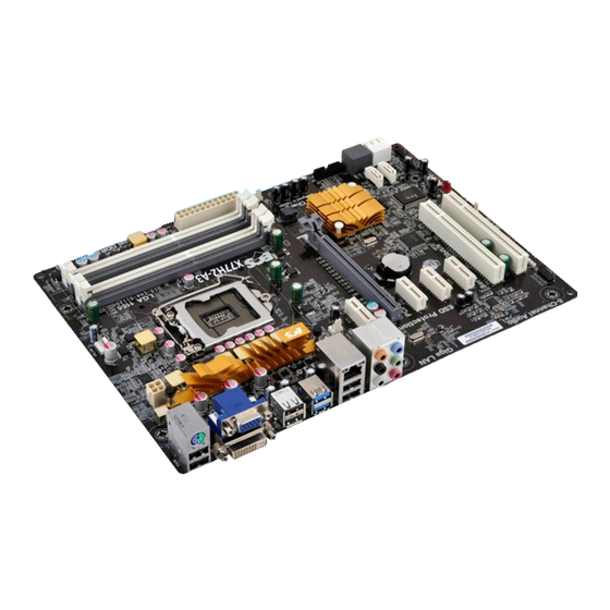
Page 8: Motherboard Components
Motherboard Components X77H2-A3 USER MANUAL... - Page 9 Front panel audio header 20. PCI1~2 32-bit add-on card slots 21. PCIE1~4 PCI Express x1 slots 22. PCIEX16 PCI Express slot for graphics interface 23. SYS_FAN1 3-pin system cooling fan connector 24. ATX12V 4-pin +12V power connector X77H2-A3 USER MANUAL...
-
Page 10: I/O Ports
7: Center & Woofer 10: Line-in 11: Front Out 8: Back Surround 12: Mic_in Rear 9: Side Surround The above port definition can be changed to audio input or audio output by changing the driver utility setting. X77H2-A3 USER MANUAL... -
Page 11: Installing The Motherboard
Place the motherboard over the mounting brackets and secure the motherboard onto the mounting brackets with screws. Do not over-tighten the screws as this can stress the motherboard. X77H2-A3 USER MANUAL... -
Page 12: Checking Jumper Settings
The following illustration shows the location of the motherboard jumpers. Pin 1 is labeled. To avoid the system instability after clearing CMOS, we recommend users to enter the main BIOS setting page to “Load Default Settings” and then “Save and Exit Setup”. X77H2-A3 USER MANUAL... -
Page 13: Installing Hardware
Lift the tail of the load lever and rotate the load plate to fully open position. Grasp the edge of the package substrate. Make sure pin 1 indicator is on your bottom-left side. Aim at the socket and place the package carefully into the socket by purely vertical motion. X77H2-A3 USER MANUAL... - Page 14 Spreader). Engage the load lever while pressing down lightly onto the load plate. Secure the load lever with the hook under retention tab. Then the cover will flick automatically. Please save and replace the cover onto the CPU socket if processor is re- moved. X77H2-A3 USER MANUAL...
-
Page 15: Installing The Cpu Cooler
B. Fasten the cooling fan supporting base onto the CPU socket on the motherboard. And make sure the CPU fan is plugged to the CPU fan connector. C. Connect the CPU cooler power connector to the CPU_FAN connector. X77H2-A3 USER MANUAL... -
Page 16: Installing Memory Modules
The slot latches are levered upwards and latch on to the edges of the DIMM. The four DDR3 memory sockets (DDR3_1, DDR3_2, DDR3_3 and DDR3_4) are divided into two channels and each channel has two memory sockets as following: Channel A: DDR3_1, DDR3_2 Channel B: DDR3_3, DDR3_4 X77H2-A3 USER MANUAL... - Page 17 1. For best performance and compatibility, we recommend that users give priority to the white DIMMs (DDR3_2/DDR3_4) when installing DIMMs. 2. We suggest users not to mix memory type. It is recommended to use the same brand and type memory on this motherboard. X77H2-A3 USER MANUAL...
-
Page 18: Installing Add-On Cards
ISA bus standard. The PCI slots on this board are PCI v3.0 compliant. Before installing an add-on card, check the documentation for the card carefully. If the card is not Plug and Play, you may have to manually configure the card before installation. X77H2-A3 USER MANUAL... - Page 19 2. The onboard PCI interface does not support 64-bit SCSI cards. Please refer the following illustrations to install the add-on card: Install the LAN Card in the PCIE X1 slot Install the VGA Card in the PCI slot Install the VGA Card in the PCIE X16 slot X77H2-A3 USER MANUAL...
-
Page 20: Connecting Optional Devices
2-4-5. Connecting Optional Devices Refer to the following for information on connecting the motherboard’s optional devices: Components Components USB3F ME_UNLOCK CASE SATA1~6 SPDIFO F_USB1~2 F_AUDIO X77H2-A3 USER MANUAL... - Page 21 A different pin assignment may cause damage or system hang- 2. CASE: Chassis Intrusion Detect Header This detects if the chassis cover has been removed. This function needs a chassis equipped with instrusion detection switch and needs to be enabled in BIOS. X77H2-A3 USER MANUAL...
- Page 22 Please make sure that the USB cable has the same pin assignment as indi- cated above. A different pin assignment may cause damage or system hang- X77H2-A3 USER MANUAL...
- Page 23 5. ME_UNLOCK: ME Unlock Header 6. COM: Onboard serial port header Connect a serial port extension bracket to this header to add a serial port to your system. X77H2-A3 USER MANUAL...
- Page 24 The front panel audio header allows the user to install auxiliary front-oriented mi- crophone and line-out ports for easier access. This header supports HD audio by default. If you want connect an AC’ 97 front panel audio to HD onboard headers, please set as below picture. X77H2-A3 USER MANUAL...
- Page 25 If you use AC’ 97 Front Panel, please don’ t tick off “Using Front Jack Detect ”. If you use HD Audio Front Panel, please tick off the option of “Using Front Jack Detect ”. * For reference only X77H2-A3 USER MANUAL...
-
Page 26: Installing A Sata Hard Drive
Attach either cable end to the connector on the motherboard. Attach the other cable end to the SATA hard drive. Attach the SATA power cable to the SATA hard drive and connect the other end to the power supply. * For reference only X77H2-A3 USER MANUAL... -
Page 27: Connecting Case Components
Connect the CPU cooling fan cable to CPU_FAN. Connect the system cooling fan connector to SYS_FAN1~2. Connect the power cooling fan connector to PWR_FAN. Users please note that the fan connector supports the CPU cooling fan of 1.1A ~ 2.2A (26.4W max) at +12V. X77H2-A3 USER MANUAL... - Page 28 24-pin power cable Connecting 4-pin power cable The ATX12V4P power connector is used to provide power to the CPU. When installing 4-pin power cable, the latches of power cable and the ATX12V4P match perfectly. 4-pin power cable X77H2-A3 USER MANUAL...
-
Page 29: Front Panel Header
50 ms to signal the power supply to switch on or off. The time requirement is due to internal de-bounce circuitry. After receiving a power on/off signal, at least two seconds elapses before the power supply recognizes another on/off signal. X77H2-A3 USER MANUAL... - Page 30 5. SPK: Speaker Connect the case speaker cable to SPK. This concludes Chapter 2. The next chapter covers the BIOS. X77H2-A3 USER MANUAL...
-
Page 31: Using Bios
When you power on the system, BIOS enters the Power-On Self Test (POST) routines. POST is a series of built-in diagnostics performed by the BIOS. After the POST routines are completed, the following message appears: Press DEL to enter SETUP X77H2-A3 USER MANUAL... -
Page 32: Resetting The Default Cmos Values
Other options lead to dialog boxes that prompt you for informa- tion. Some options (marked with an icon ) lead to submenus that enable you to change the values for the option. Use the cursor arrow keys to scroll through the items in the submenu. X77H2-A3 USER MANUAL... -
Page 33: Bios Navigation Keys
Select the boot icon and press <Enter> or double click the left key of the mouse to display the screen. Then you can choose the boot device. Advanced Select the advanced icon and press <Enter> or double click the left key of the mouse to display the screen. X77H2-A3 USER MANUAL... -
Page 34: Main Menu
The Date and Time items show the current date and time on the computer. If you are running a Windows OS, these items are automatically updated whenever you make changes to the Windows Date and Time Properties utility. X77H2-A3 USER MANUAL... -
Page 35: Advanced Menu
/Click: Select Item Super IO Configuration Intel(R) Rapid Start Technology Enter/Dbl Click : Select Intel(R) Smart Connect Technology +/- : Change Opt. F1: General Help F2: Previous Values F3: Optimized Defaults F4: Save & Exit ESC/Right Click: Exit X77H2-A3 USER MANUAL... -
Page 36: Lan Configuration
Use this item to enable or disable UEFI network stack. Ipv4/6 PXE Support (Enabled) Use these items to enable or disable the Ipv4/6 PXE Boot support. If disabled IPV4/ 6 PXE boot option will not be created. Press <Esc> to return to the Advanced Menu page. X77H2-A3 USER MANUAL... -
Page 37: Pc Health Status
Delta T CPU/System/Power Smart Fan Control (Enabled) This item enables you to define the CPU/system/Power by smartly adjusting the CPU/system/Power Fan. When it is set at certain temperature, the CPU/system/ Power Fan PWM value will change accordingly. X77H2-A3 USER MANUAL... - Page 38 CPU Fan Speed • System Fan Speed • PWR Fan Speed • CPU Voltage • AXG Voltage • IMC Voltage • DIMM Voltage • PCH Voltage • • +12V Press <Esc> to return to the Advanced Menu page. X77H2-A3 USER MANUAL...
-
Page 39: Power Management Setup
EUP Function (Enabled) This item allows user to enable or disable EUP support. Power LED Type (Dual Color LED) This item shows the type of the Power LED. Press <Esc> to return to the Advanced Menu page. X77H2-A3 USER MANUAL... -
Page 40: Acpi Configuration
F4: Save & Exit ESC/Right Click: Exit ACPI Sleep State [S3(Suspend to RAM)] This item allows user to enter the ACPI S3 (Suspend to RAM) Sleep State (default). Press <Esc> to return to the Advanced Menu page. X77H2-A3 USER MANUAL... -
Page 41: Cpu Configuration
This item shows the computer supports Intel HT Technology. Intel VT-x Technology (Supported) This item shows the computer supports Intel VT-x Technology. Hyper-threading (Enabled) This item only available when the chipset supports Hyper-threading and you are using a Hyper-threading CPU. X77H2-A3 USER MANUAL... - Page 42 Use this item to enable or disable CPU C6(ACPI C3) report to OS. Enhanced Halt (C1E) (Enabled) Use this item to enable the CPU energy-saving function when the system is not run- ning. Press <Esc> to return to the Advanced Menu page. X77H2-A3 USER MANUAL...
-
Page 43: Sata Configuration
SATA Port 2~6 (Not Present) This motherboard supports six SATA channels and each channel allows one SATA device to be installed. Use these items to configure each device on the SATA channel. Press <Esc> to return to the Advanced Menu page. X77H2-A3 USER MANUAL... -
Page 44: Usb Configuration
All USB Devices (Enabled) Use this item to enable or disable all USB devices. Legacy USB Support (Enabled) Use this item to enable or disable support for legacy USB devices. Press <Esc> to return to the Advanced Menu page. X77H2-A3 USER MANUAL... -
Page 45: Super Io Configuration
This item allows you to enable or disable serial port. Device Settings (IO=3F8h; IRQ=4) This item shows the information of the device settings. Change Settings (Auto) Use this item to change device settings. Press <Esc> to return to the Advanced menu page. X77H2-A3 USER MANUAL... -
Page 46: Intel Rapid Start Technology
+/- : Change Opt. F1: General Help F2: Previous Values F3: Optimized Defaults F4: Save & Exit ESC/Right Click: Exit Intel(R) Rapid Start Technology (Disabled) Use this item to enable or disable the Intel(R) Rapid Start Technology. X77H2-A3 USER MANUAL... -
Page 47: Intel Smart Connect Technology
Use this item to enable/disable ISCT WLAN Power Control. ISCT WWAN Power Control (Enabled) Use this item to enable/disable ISCT WWAN Power Control. ISCT Sleep Duration Value Format (Actual Time) Use this item to select actual time or duration in seconds. (ISCT 2.0) X77H2-A3 USER MANUAL... -
Page 48: Chipset Menu
When set to Fixed Mode, the graphics driver will reserve a fixed position of the sys- tem memory as graphics memory, according to system and graphics requirements. IGD Multi-Monitor (Disabled) This item allows you to enable or disable the IGD Muti-Monitor. X77H2-A3 USER MANUAL... - Page 49 This item enables or disables the warning if the case is opened up, and the item below indicates the current status of the case. Chassis Opened (No) This item indicates whether the case has been opened. Press <Esc> to return to the Chipset Menu page. X77H2-A3 USER MANUAL...
- Page 50 +/- : Change Opt. F1: General Help F2: Previous Values F3: Optimized Defaults F4: Save & Exit ESC/Right Click: Exit ME FW Version (8.1.0.1248) This item shows the ME FW version. Press <Esc> to return to the chipset menu page. X77H2-A3 USER MANUAL...
-
Page 51: Mb Intelligent Bios Iii) Menu
Core Current Max (1/8 Amp) +/- : Change Opt. Long Duration Power Limit Override 1440 F1: General Help Long Duration Maintained F2: Previous Values Short Duration Power Limit Override 1680 F3: Optimized Defaults ESC/Right Click: Exit X77H2-A3 USER MANUAL... - Page 52 Use this item to control the time window over PL1 Value should be maintained. This is for Turbo Mode. Short Duration Power Limit Override (1680) Intel(R) Turbo Boost Technology will use this power limit for a very short duration. After that, the Long Duration Power Limit will be honored. X77H2-A3 USER MANUAL...
- Page 53 This item specifies the write recovery time. Row Refresh Cycle Time (tRFC) (128) This item specifies the row refresh cycle time. Active to Active Delay (tRRDmin) (5) This item controls the ACTIVE bank x to ACTIVE bank y in memory clock cycles. X77H2-A3 USER MANUAL...
- Page 54 2. Press and hold the “Page Up Key (PgUp)” of the keyboard, and then boot the PC 3. Two seconds after the PC boots up, release the “Page Up Key (PgUp)”. 4. The BIOS returns to the default setting by itself. X77H2-A3 USER MANUAL...
-
Page 55: Boot Menu
This item enables or disables quiet boot. Boot mode select (LEGACY) Use this item to select boot mode. Set Boot Priority This item enables you to set boot priority for all boot devices. Boot Option #1/2/3/4/5/6/7 These items show the boot priorities. X77H2-A3 USER MANUAL... - Page 56 Launch Video OpROM policy (Legacy only) This controls the execution of UEFI and Legacy Video OpROM. Other PCI device ROM priority (Legacy OpROM) For PCI devices other than Network, Mass storage or Video defines which OpROM to launch. X77H2-A3 USER MANUAL...
-
Page 57: Security Menu
Secure Boot Mode (Custom) This item is used to select secure boot mode, when you select standard mode, se- cure boot policy is fixed; when you select custom mode, the image execution policy and secure boot key databases are changeable. X77H2-A3 USER MANUAL... - Page 58 These items allow you to select image execution policy per device path on security violation. Only users logged with administrative password can exercise query user policy setting. Press <Esc> to return to the Security Menu page. X77H2-A3 USER MANUAL...
- Page 59 This item shows the information of the forbidden signature database. Append an entry to KEK/DB/DBX This item launches the file browser to Append new signature database from the file. The file data must be formatted as Efi Variable with TimeBased Authenticated Header. X77H2-A3 USER MANUAL...
-
Page 60: Exit Menu
This item enables you to save the changes that you have made as user defaults. Restore User Defaults This item enables you to restore user defaults to all the setup options. Boot Override Use this item to select the boot device. X77H2-A3 USER MANUAL... -
Page 61: Updating The Bios
BIOS jumper, reset the jumper to protect the newly installed BIOS from being overwritten. The computer will restart automatically. This concludes Chapter 3. Refer to the next chapter for information on the software supplied with the motherboard. X77H2-A3 USER MANUAL... - Page 62 Memo X77H2-A3 USER MANUAL...
-
Page 63: Using The Motherboard Software
Click Setup. The installation program begins: The following screens are examples only. The screens and driver lists will be different according to the motherboard you are installing. The motherboard identification is located in the upper left-hand corner. X77H2-A3 USER MANUAL... - Page 64 Windows 8 will show the following screen after system restart, you must select “Desktop” in the bottom left to install the next driver. X77H2-A3 USER MANUAL...
-
Page 65: Manual Installation
ECS Utility Software (Intelligent EZ Utility) ECS Intelligent EZ Utility provides friendly interfaces under Windows O.S, which makes your computing more easily and conveniently. These software(s) are subject to change at anytime without prior notice. Please refer to the support disk for available software. - Page 66 Just select the one you prefer and start to download and install the drivers. eBLU ECS eBLU utility makes BIOS update faster and easier. eBLU will list the latest BIOS with a default check-mark. Click”install” button to install. Microsoft .NET Framework 3.5 is required.
-
Page 67: Intel® Matrix Storage Manager Raid Configuration
Create an Intel Matrix Storage Manager driver disk for Windows OS in- stallation. See section “Creating a RAID driver disk” for details. ® ® Install the Intel Matrix Storage Manager driver after the Windows had been installed. X77H2-A3 USER MANUAL... -
Page 68: Entering Intel Matrix Storage Manager Raid Bios Utility
During POST, press <Ctrl-I> to enter the Intel Matrix Storage Manager RAID BIOS menu. ® The main Intel Matrix Storage Manager RAID BIOS menu appears. Use the arrow keys to move the color bar and navigate through the items. X77H2-A3 USER MANUAL... -
Page 69: Creating A Raid Set
Key in the RAID volume capacity. Use the up/down arrow to choose the Capacity. The default value indicates the maximum capacity using the selected disks. Entering a lower capacity allows you to create a second volume on these disks. X77H2-A3 USER MANUAL... - Page 70 RAID 1 (Mirror) is set to provide the data backup. If you want to set RAID 0, you need to set the 2nd Boot Device item in the BIOS to Intel Volume0. See section “Advanced Setup” for details. X77H2-A3 USER MANUAL...
-
Page 71: Deleting A Raid Set
Use the space bar to select the RAID set you want to delete. Press the <Del> key to delete the set. A dialogue box appears to confirm the action. Press <Y> to confirm; other- wise, press <N>. Pressing <Y> deletes all the data in the HDDs. X77H2-A3 USER MANUAL... -
Page 72: Reseting Disks To Non-Raid
Intel Matrix Storage Manager RAID BIOS utility. A dialogue box appears to confirm the action. Press <Y> to confirm; otherwise, press ® <N> to return to the Intel Matrix Storage Manager RAID BIOS menu. X77H2-A3 USER MANUAL... -
Page 73: Trouble Shooting
Before calling for technical support or returning for warranty, this chapter may help to address some of the common questions using some basic troubleshooting tips. You may also log onto our ECS website for more information: http:// www.ecs.com.tw/ECSWebSite/Support/Support_FAQ.aspx?MenulD=49& childid=M 49&LanlD=0 a) System does not power up and the fans are not running. -
Page 74: Start Up Problems After Prolong Use
5. Check whether there is any bulked up electrolytic capacitor or abnormal component. Please logo onto our ECS website: http://www.ecs.com.tw/ECSWebSite/Support/ Technical_Support_List.aspx?MenuID=50&LanID=0 for more information. Maintenance and care tips Your computer, like any electrical appliance, requires proper care and maintenance. - Page 76 Memo X77H2-A3 USER MANUAL...
Need help?
Do you have a question about the X77H2-A3 and is the answer not in the manual?
Questions and answers