
Subscribe to Our Youtube Channel
Related Manuals for Bugera 1990


Summary of Contents for Bugera 1990
- Page 1 A50-67030-08001 1990 User Manual...
-
Page 2: Important Safety Instructions
Important safety instructions CAUTION: High voltage! Risk of death! High voltages of up to 500 V DC may be present inside the casing for long periods after being disconnected from the mains. To avoid lethal electric shock, do not open the casing. There are no user-serviceable components inside. -
Page 3: Table Of Contents
Online registration ......................4 Control elements ................5 Front panel ........................5 Rear panel ........................5 Footswitch ........................6 Inside the BUGERA ......................7 INSTRUCTIONS FOR QUALIFIED SERVICE PERSONNEL ONLY ...........7 Wiring the BUGERA ................7 Audio connections ................8 Specifications ................... 9 Limited warranty ................10... -
Page 4: Important Notice
Online registration attempt is made to move the amplifier. This reduces the risk of mechanical damage to the sensitive valve ele- Please do remember to register your new BUGERA equip- ments. ment right after your purchase by visiting www.bugera- amps.com and kindly read the terms and conditions of ATTENTION! TO AVOID DAMAGE TO YOUR our warranty carefully. -
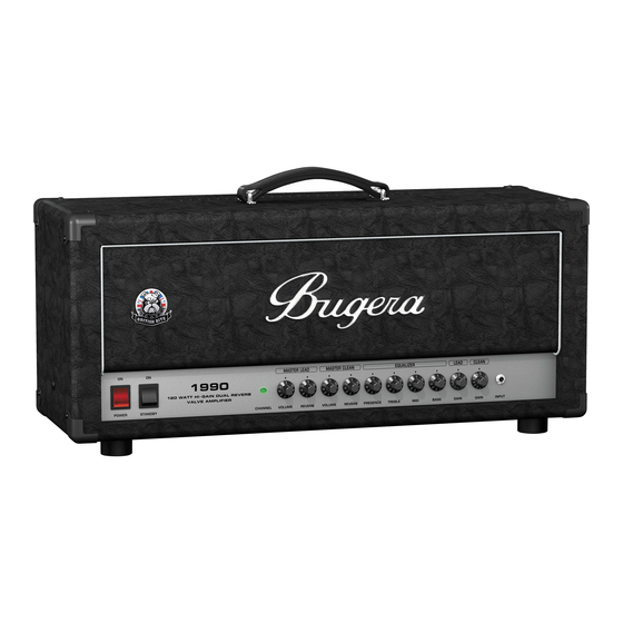
Page 5: Control Elements
VOLUME control that lets you adjust the volume level of the LEAD channel. The jack labeled INPUT is the 1/4" input connector on the BUGERA for hooking up your guitar. Use a This REVERB rotary knob adjusts the effect level of commercially available 1/4" mono cable. -
Page 6: Footswitch
Always apply the value that This is the SERIAL NUMBER of the amplifier. is identical to the impedance of the used speaker cabinet. Please also read „Wiring the BUGERA“. Footswitch LOUDSPEAKER outputs (¼" Both the paralleled mono jacks) are used to connect the speaker cabinet(s). -
Page 7: Inside The Bugera
Inside the BUGERA The BUGERA amplifier has two paralleled LOUDSPEAKER outputs which are used to connect one or two speaker cabinets. DANGER! If you only connect one speaker cabinet, be sure that the High voltage! Risk of death! IMPEDANCE switch is set to match the impedance of the High voltages of up to 500 V DC may be connected cabinet. -
Page 8: Audio Connections
FX LOOP. What’s more, the RECORDING output is connected to a mixer’s line chan- The inputs and outputs of the BUGERA amplifier use nel to feed the signal to a recording device. The speaker mono jack connectors. -
Page 9: Specifications
Specifications PREAMP SECTION Valves Type 2 x ECC83A 1 x ECC83 Instrument Input Impedance 1 MΩ Clean Channel Nominal input level –10 dBV Minimum input level –50 dBV Maximum input level 0 dBV Lead Channel Nominal input level –80 dBV Minimum input level –92 dBV Effects Send... -
Page 10: Limited Warranty
Return authorization number To obtain warranty service, the buyer (or his authorized dealer) must call BEHRINGER as exclusive distributor of BUGERA products (see enclosed list) during normal business hours BEFORE returning the product. All inquiries must be accompanied by a description of the problem. The buyer or his au- thorized dealer will receive a return authorization number Subsequently, the product must be returned in its original shipping carton, together with the return authorization number.
Need help?
Do you have a question about the 1990 and is the answer not in the manual?
Questions and answers