Alarm Lock PG21 Series Installation Instructions Manual
Pilfergard door alarms
Hide thumbs
Also See for PG21 Series:
- Installation instructions (4 pages) ,
- Installation template (2 pages) ,
- Installation instructions manual (9 pages)
Table of Contents
Advertisement
ALARM LOCK
345 Bayview Avenue
Amityville, New York 11701
For Sales and Repairs, (800) 645-9445
For Technical Service, (800) 645-9440
© ALARM LOCK 2006
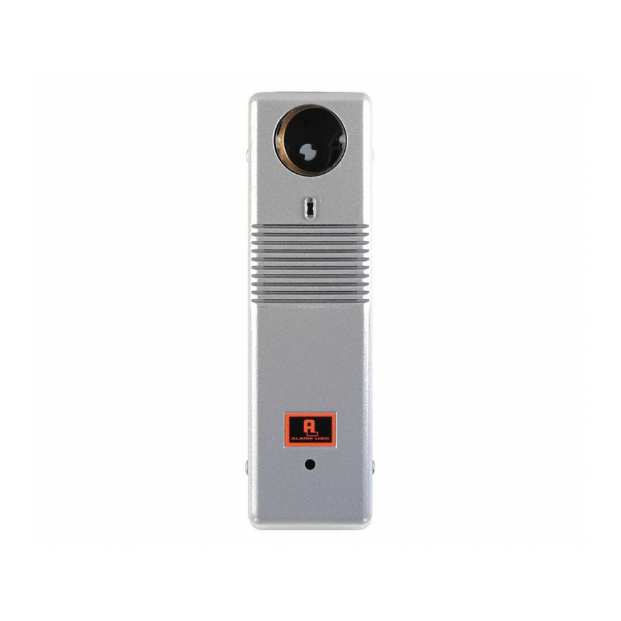
DESCRIPTION
The PG21 is a microprocessor-controlled door alarm for sur-
face mounting on a door or door frame. Typical applications
include emergency fire escape doors, nursing home stairwell
doors, rear restaurant and theater doors. The PG21 is de-
signed to continually monitor the status of a door.
opened, the protected door triggers an alarm sounder, an op-
tional strobe or can activate another device via a Form-C re-
lay. It has various programmable features including:
•
Four Siren Sounds
•
Four "Alarm Modes" for a variety of applications (see page 5).
•
Programmable Time Delays
•
Battery Operated (Battery life approximately 2 ½ years)
•
External Power Supply Capability
•
Built-in Door Bell (Requires button installation)
•
Cover Tamper Protection (Unauthorized removal trips alarm)
•
"Key Lock Tamper" (Cover cannot be removed without key)
•
Accepts standard mortise cylinders
•
Multiple Door Monitoring (External Reed Switch Contacts)
•
Form-C Relay (Connect to fire/burglary panel or other device)
•
Annunciator Feature (Beeps when door opens)
•
Two Operating Modes: "Always Armed" and "On/Off"
•
Strobe Feature (PG21MSS models only)
•
Status Indicator
The PG21 unit is usually mounted on the interior of the door
frame or door and is paired with a magnet (Magnetic Actuator)
mounted on the opposing side of the door gap. Opening the
door, when armed, will activate the alarm.
shipped from the factory in "Always Armed" mode (if key is re-
moved, unit automatically re-arms) and can be converted to a
manual "On/Off" mode (allowing the operator to manually arm
or disarm with the key). The Status indicator (located on the
front of the Housing Cover) signifies whether the unit is armed
or disarmed (red indicates armed status). A selectable annun-
ciator feature beeps to signal the opening of the door while the
unit is disarmed.
SPECIFICATIONS
Dimensions: 11" x 2½" x 2 3/8" (22.8cm x 6.3cm x 6.8cm)
(LxWxD) (Length 11" with Strobe, 9" without Strobe).
Finish:
Metallic
Silver
(PG21MB); Red (PG21RD); Metallic Silver with
Strobe (PG21MSS)
Power Requirements: 9-Volt Alkaline Battery (supplied).
The PG21 may also be used with Model PP100
(optional) or other power supply providing 9-12Vdc at
300mA. Internal battery may be used simultaneously
Pilfergard Door Alarms
INSTALLATION INSTRUCTIONS
Publicly traded on NASDAQ
Symbol: NSSC
The PG21 is
(PG21MS);
Metallic
Bronze
PG21 Series
with external power supply.
Sounding Device: Piezo electronic sounder sweep siren,
steady or pulsing, 110dB at 10 feet
Shipping Weight: 1 lb, 10 oz.
Relay Contacts: (Form-C) rated at 24VAC/DC at 1A (non-
inductive).
When
A. INSTALLATION: PRELIMINARY STEPS
Installation is divided into 5 main steps: (A) Preliminary, (B)
Wiring, (C) Configuration, (D) Mounting and (E) Testing.
1. Choose a suitable location.
mounted on a door, and the Magnetic Actuator is mounted
to (or inside) the door jamb. However, if the PG21 will
have a doorbell or any external wiring, give careful consid-
eration to the mounting location and make allowances for
all necessary wiring. For example, if you wish to monitor
multiple doors, choose a generally central location as
wires (and reed switch contacts) will need to run to all
doors in series. If you mount the PG21 on a door, the
Baseplate must be mounted far enough away from the
edge of the door to prevent unit from striking the door jam
when opening the door.
2. Examine the enclosed template.
plate provides mounting hole locations (drawn in solid cir-
cular lines) for several door types. Use the four corner
holes for the Baseplate as shown on the template. Note:
Certain narrow-stile doors require only two holes for the
Baseplate.
3. Mark and drill holes (use 1/8" bit, 1" deep) on the door
and jamb as per the template directions. Hole locations
are drawn in solid circular lines.
4. External Wiring. Mark and drill the hole (shown on the
template) for external wiring such as doorbell, reed switch
or relay wiring.
5. Knock out the necessary holes from the Baseplate and
install on the door with the supplied #8 sheet-metal
screws.
6. Temporarily mount the Housing Cover into the Base-
plate to aid in positioning the Magnetic Actuator location.
Mount as follows: Remove all keys from cylinder (thus
ensuring the cylinder is in a 12:00 position). Hold the
Housing Cover vertically with the inside facing toward you
(the PC board and jumpers can been seen at bottom),
slide the switch to the right. (Note: Each time the Hous-
ing Cover is removed, the switch MUST be moved to the
right before mounting). Hook the Housing Cover into the
clip at the bottom of the Baseplate, then gently snap the
top of the Housing cover into the top of the Baseplate. DO
NOT FORCE. Note: If the switch is in the wrong position
(not moved to the right), or if a key is accidentally left in-
side the cylinder, the Housing Cover is specifically de-
signed NOT to lock into the Baseplate.
WI738F 1/06
Most often, the PG21 is
The two-sided tem-
1
Advertisement
Table of Contents

Subscribe to Our Youtube Channel
Related Manuals for Alarm Lock PG21 Series


Summary of Contents for Alarm Lock PG21 Series
- Page 1 Amityville, New York 11701 For Sales and Repairs, (800) 645-9445 For Technical Service, (800) 645-9440 Publicly traded on NASDAQ Symbol: NSSC © ALARM LOCK 2006 WI738F 1/06 DESCRIPTION with external power supply. Sounding Device: Piezo electronic sounder sweep siren, The PG21 is a microprocessor-controlled door alarm for sur- steady or pulsing, 110dB at 10 feet face mounting on a door or door frame.
- Page 2 (+) red to Terminal 7; negative (-) black this end to Terminal 6. Leave in the internal battery as a backup Assembly battery. If using the Alarm Lock PP100 Power Supply, Fig 3a Fig. 3b Fig. 3c Figs. 3a-3c: Disconnect Torsion Spring from Cam Assembly: Fig 3a displays the Torsion Spring as it is installed from the factory (thus "Always Armed"...
- Page 3 door is closed within that two minute period. Jumper moved to the "lower" position disables the timeout, keeping the siren on until manually reset. To indicate that an alarm has occurred (Alarm Memory), the LED 1 2 3 4 5 6 7 8 9 will start flashing.
- Page 4 LED to light again; ignore (a) install mortise cylinder HW1154 subsequent indications). (Alarm Lock Model CEM, (b) Similarly, place the Magnetic Actuator against the wall, optional) into the Housing adjacent to the top of the unit. Slowly slide the Magnetic...
- Page 5 CONFIGURATION EXAMPLES Use the PG21 for a variety of applications--emergency fire escape doors, nursing home stairwell doors, rear restaurant doors, and many others. To change the way the PG21 operates when in use, two areas of the PG21 can be configured: (a) the PC Board jumpers and (b) the Torsion Spring connection.
- Page 6 CONFIGURATION EXAMPLES (cont'd) MODE NAME FEATURE DETAILS JUMPER POSITIONS For Multiple Door Installa- A PG21 installed on several doors each with its unique siren sound. Four siren sounds: Sweep, Pulsing Sweep, Steady, Pulsing Steady. Sweep tions Set a different siren sound for each door in order to easily identify which door has been accessed.
- Page 7 EXPLODED VIEW Fig. 7 Exploded view with part numbers...
-
Page 8: Alarm Lock Limited Warranty
In no event shall ALARM LOCK be liable for an amount in excess of ALARM LOCK's original selling price of the product, for any loss or damage, whether direct, indirect, incidental, consequential, or otherwise arising out of any failure of the product.
Need help?
Do you have a question about the PG21 Series and is the answer not in the manual?
Questions and answers