Alarm Lock PG21 Series Installation Instructions Manual
Pilfergard door alarms
Hide thumbs
Also See for PG21 Series:
- Installation instructions manual (9 pages) ,
- Installation instructions (4 pages) ,
- Installation template (2 pages)
Table of Contents
Advertisement
345 Bayview Avenue, Amityville, New York 11701
For Sales and Repairs 1-800-ALA-LOCK
For Technical Service 1-800-645-9440
or visit us at
http://tech.napcosecurity.com/
(Note: Technical Service is for security professionals only)
Publicly traded on NASDAQ
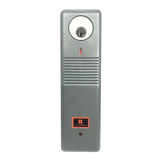
DESCRIPTION
The PG21 is a microprocessor-controlled door alarm for sur-
face mounting on a door or door frame. Typical applications
include emergency fire escape doors, nursing home stairwell
doors, rear restaurant and theater doors. The PG21 is de-
signed to continually monitor the status of a door. When
opened, the protected door triggers an alarm sounder, an
optional strobe or can activate another device via a Form-C
relay. It has various programmable features including:
• Four Siren Sounds
• Various "Alarm Modes" (see pages 5-6).
• Programmable Time Delays
• Battery Operated (Battery life approximately 2½ years)
• External Power Supply Capability
• Built-in Door Bell (Requires button installation)
• Cover Tamper (Unauthorized removal trips alarm)
• "Key Lock Tamper" (Key required for cover removal)
• Accepts standard mortise cylinders
• Multiple Door Monitoring (External Reed Switch Contacts)
• Form-C Relay (Connect to security panel or other device)
• Annunciator Feature (Beeps when door opens)
• Two Operating Modes: "Always Armed" and "On/Off"
• Strobe Feature (PG21MSS models only)
• Status Indicator
• LED Time-Out Flashes
The PG21 is usually mounted on the interior of the door
frame or door and is paired with a magnet (Magnetic Actua-
tor) mounted on the opposing side of the door gap. Opening
the door, when armed, will activate the alarm. The PG21 is
shipped from the factory in "Always Armed" mode (if key is
removed, unit automatically re-arms) and can be converted
to a manual "On/Off" mode to (allows the operator to manu-
ally arm or disarm with the key).
(located on the front of the Housing Cover) signifies whether
the unit is armed or disarmed (red indicates armed status).
A selectable Annunciator Feature beeps to signal the open-
ing of the door while the unit is disarmed.
SPECIFICATIONS
Dimensions (LxWxD): 11" x 2½" x 2 3/8" (28 x 6.4 x 6.cm)
(Length 11" (28cm) with Strobe, 9" (23cm) without Strobe)
Finish:
Metallic Silver (PG21MS); Metallic Bronze
(PG21MB); Red (PG21RD); Metallic Silver with Strobe
(PG21MSS)
Power Requirements: 9V alkaline battery (supplied). May
also be powered by the Model PP100 (optional) or other
power supply providing 9-12VDC at 300mA. Internal battery
may be used simultaneously with external power supply
Sounding Device: Piezo electronic sounder sweep siren,
steady or pulsing: 110dB at 10 feet (3.05m)
Shipping Weight: 1 lb, 10 oz. (737.1g)
Relay Contacts: (Form-C) rated at 24VAC/DC at 1A (non-
inductive)
PG21 Series Pilfergard Door Alarms Installation Instructions
INSTALLATION INSTRUCTIONS
Symbol: NSSC
© ALARM LOCK 2022
The Status Indicator
PG21 Series
Pilfergard Door Alarms
A. INSTALLATION: PRELIMINARY STEPS
Installation is divided into 5 main steps: (A) Preliminary, (B)
Wiring, (C) Configuration, (D) Mounting and (E) Testing.
1. Choose a suitable location. Most often, the PG21 is
mounted on a door, and the Magnetic Actuator is mount-
ed to (or inside) the door jamb. However, if the PG21 will
have a doorbell or any external wiring, give careful con-
sideration to the mounting location and make allowances
for all necessary wiring. For example, if you wish to mon-
itor multiple doors, choose a generally central location as
wires (and reed switch contacts) will need to run to all
doors in series. If you mount the PG21 on a door, the
Baseplate must be mounted far enough away from the
edge of the door to prevent unit from striking the door jam
when opening the door.
2. Examine the enclosed template. The two-sided tem-
plate provides mounting hole locations (drawn in solid
circular lines) for several door types. Use the four corner
holes for the Baseplate as shown on the template. Note:
Certain narrow-stile doors require only two holes for the
Baseplate.
3. Mark and drill holes (use 1/8" bit, 1" deep) on the door
and jamb as per the template directions. Hole locations
are drawn in solid circular lines.
4. External Wiring. Mark and drill the hole (shown on the
template) for external wiring such as doorbell, reed
switch or relay wiring.
5. Knock out the necessary holes from the Baseplate
and install on the door with the supplied #8 sheet-metal
screws.
6. Temporarily mount the Housing Cover into the
Baseplate to aid in positioning the Magnetic Actuator lo-
cation.
Mount as follows: Remove all keys from cylinder (thus
ensuring the cylinder is in a 12:00 position). Hold the
Housing Cover vertically with the inside facing toward
you (the PC board and jumpers can been seen at bot-
tom), slide the switch to the right. (Note: Each time the
Housing Cover is removed, the switch MUST be moved
to the right before mounting). Hook the Housing Cover
into the clip at the bottom of the Baseplate, then gently
snap the top of the Housing cover into the top of the
Baseplate. DO NOT FORCE. Note: If the switch is in
the wrong position (not moved to the right), or if a key is
accidentally left inside the cylinder, the Housing Cover is
specifically designed NOT to lock into the Baseplate.
7. Position the Magnetic Actuator as indicated by the red
sticker on the side of the Housing Cover. If stickers were
removed, place the Magnetic Actuator 1½ " from the bot-
tom edge of the Baseplate. Mark holes and (as with the
Baseplate) use a 1/8" (0.125") bit, and drill the hole 1"
deep.
8. Install the Magnetic Actuator with the supplied #8
sheet-metal screws (1"). Be sure to insert the Magnet
WI738HLF 3/22
1
Advertisement
Table of Contents

Subscribe to Our Youtube Channel
Related Manuals for Alarm Lock PG21 Series


Summary of Contents for Alarm Lock PG21 Series
- Page 1 Shipping Weight: 1 lb, 10 oz. (737.1g) 8. Install the Magnetic Actuator with the supplied #8 Relay Contacts: (Form-C) rated at 24VAC/DC at 1A (non- sheet-metal screws (1"). Be sure to insert the Magnet inductive) PG21 Series Pilfergard Door Alarms Installation Instructions...
-
Page 2: Mechanical Configuration
...then minal 6. Leave in the internal battery as a backup battery. If unhook this end using the Alarm Lock PP100 Power Supply, connect the two Assembly battery clips to the unit and the internal battery as labeled. Fig. 3a Fig. -
Page 3: Jumper Options
J4: Security Level. Default setting (jumper at "upper" posi- tion--High Security) enables a latching alarm when tripped--siren remains on for 1 minute or until turned off PG21 Series Pilfergard Door Alarms Installation Instructions... -
Page 4: Field Test
"Standby Mode" (switch closed). Therefore, when every minute, indicating the need for battery replacement. performing Magnet Alignment Mode, do not install the Tamper Screw until the magnet has been aligned and se- PG21 Series Pilfergard Door Alarms Installation Instructions... -
Page 5: Configuration Examples
1 2 3 4 5 6 7 8 9 • No key needed to silence, just close door. • Door Ajar Mode with 2 • Allows door to remain open up to 2 minutes without an alarm. minute delay. continued PG21 Series Pilfergard Door Alarms Installation Instructions... - Page 6 PG21 will beep for 2 seconds when door is opened while disarmed. 1 2 3 4 5 6 7 8 9 • Maximum High Volume • Jumper J8 must be down to enable annunciator. • Jumper J9 down = annunciator maximum high volume. PG21 Series Pilfergard Door Alarms Installation Instructions...
-
Page 7: Exploded View
EXPLODED VIEW H354 7/16" SC549 SC549 Fig. 9: Exploded view with part numbers PG21 Series Pilfergard Door Alarms Installation Instructions... -
Page 8: Alarm Lock Limited Warranty
This warranty shall not apply to any equipment, or any In no event shall ALARM LOCK be liable for an amount part thereof, which has been repaired by others, improp- in excess of ALARM LOCK's original selling price of the...
Need help?
Do you have a question about the PG21 Series and is the answer not in the manual?
Questions and answers