Table of Contents
Advertisement
Quick Links
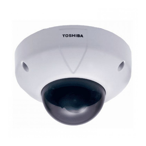
NETWORK CAMERA
Model
Operation Manual
To get started, read the separate "Safety Precautions" carefully.
For information on the latest products and peripheral devices, refer to
the following Web page.
Ihttp://www.netcam.toshiba.com
The above URL is subject to change without prior notice. If the URL
changes, refer to the Toshiba website
(http://www.cctv.toshiba.com).
This User's Guide applies to the firmware version R1.01 and later.
Downloaded from
www.Manualslib.com
: IK-WR01A
manuals search engine
WR01-01
Advertisement
Table of Contents

Related Manuals for Toshiba WR01A - PoE Vandal Resistant Network Dome Camera


Summary of Contents for Toshiba WR01A - PoE Vandal Resistant Network Dome Camera
-
Page 1: Network Camera
For information on the latest products and peripheral devices, refer to the following Web page. Ihttp://www.netcam.toshiba.com The above URL is subject to change without prior notice. If the URL changes, refer to the Toshiba website (http://www.cctv.toshiba.com). This User’s Guide applies to the firmware version R1.01 and later. WR01-01 Downloaded from www.Manualslib.com... -
Page 2: Gimportant Safety Instructions
Important Safety Instructions Be sure to read “IMPORTANT SAFEGUARDS” in the separate “Safety Precautions.” Downloaded from www.Manualslib.com manuals search engine... -
Page 3: Table Of Contents
INTRODUCTION FEATURES & DESCRIPTION IK-WR01A has the following features: (1) Flush/Surface mount. (2) IP66 Standard for dust and water resistance. (3) Built in vari-focal lens with auto-iris Focal length 3.0~8.0mm. (4) Incorporated 1/3" type CCD image sensor gives high resolution and excellent sensitivity 480 lines horizontal resolution 0.4 lx minimum illumination with tint dome cover (5) 50dB Signal-To Noise Ratio... - Page 4 INTRODUCTION (Cont.) Viewing and Operation GViewing ......................... 34 Viewing Images ....................34 Camera Window Screen ................35 • Menu that is displayed when right-clicking on the image ....... 35 • Adjusting Images on the Camera ..............36 Adding Images ....................38 GViewing Logs ......................
-
Page 5: Names And Features Of Parts
Names and Features of Parts Lens Iris ADJ Mode Setting Switch Counterclockwise: The picture becomes darker. BLC (Backlight Compensation Switch) Clockwise: The picture becomes With the switch on, it adjusts brighter. the backlight automatically to "Optimum Value" is at default setting. obtain the best possible image. - Page 6 INTRODUCTION (Cont.) Video Out Jack Connect a video monitor to the video output jack. RJ45 Connector (Option) Ethernet Port Connect a LAN cable to the port. A PoE compatible hub is also supported. AC24V/DC12V Power Plug Terminal Connect an AC24V/DC12V power plug to the terminal.
-
Page 7: Installation/Setup
Installation/Setup G Connecting to a Video Monitor G Line-Lock Control G Adjusting a Lens G Setting Up the Network Camera Environment G Connecting the Camera and Personal Computer by Network G Using the Camera Search Application “Camera Finder” G Changing Administrator Login ID and Password G Setting up Access Restriction G Configuring the Network... -
Page 8: Ginstallation
INSTALLATION Connect the cable of the camera and the cable from the designated power supply with respective connectors. Screws for securing the camera and mounting base to the ceiling or wall are not supplied with the unit. Use appropriate screws. NOTE •... - Page 9 Tilt rotation Horizontal adjustment ring Horizontal rotation Tilt Lock ∞ Pan Lock Focus NEAR lock lever WIDE TELE Zoom Remove three silver lock lever transport protection screws. Transport Protection Screws (silver) To obtain a level image, turn the Horizontal Adjustment Ring. Turn the pan lock counterclockwise to loosen it.
- Page 10 INSTALLATION (Cont.) The lens tilt angle can be adjusted by loosening the tilt lock 2. After adjusting, tighten the tilt lock 2. Adjust the zoom position by loosening the zoom lock lever 3. After adjusting, tighten the zoom lock lever When installing the camera on a wall, manipulate the horizontal adjustment ring 4 to adjust the inclination of the image.
-
Page 11: Installing The Camera Unit
Installing the Camera Unit I Installation to Wall or Ceiling with Mounting Base (Surface Mount Installation) Unit: mm (inches) Cable access hole ø27 mm (1.06inch) • When installing the camera unit on the 4 6 m m ( 1 . 8 1 i n wall, mount it with the drain groove on c h ) Mounting Base center... -
Page 12: Installation To Junction Box With Bracket (Flush Mount Installation)
INSTALLATION (Cont.) I Installation to Junction Box with Bracket (Flush Mount Installation) Unit: mm (inches) 4 6 m m ( 1 . 8 1 in c h ) Junction Box 8 3 . 5 m m ( 3 . 2 9 i n c Bracket Screws (not supplied) Note the direction of the... -
Page 13: Change Of Dome Cover
I Change of Dome Cover Screws (x3) Retainer plate Put the protruding side downward. The protruding portion should be set in the groove of the shock damper. Shock damper cushion Note the direction of the damper cushion. The groove should be face up. Dome cover Gasket Top cover... -
Page 14: Gconnecting To A Video Monitor
Connecting to a Video Monitor Connecting to a Video Monitor You can view camera images on the video monitor. Video Monitor LAN cable Either AC24V or DC12V Rear On the power supply, use a PoE compatible hub, or connect • AC24V or DC12V power plug. -
Page 15: About The Power Select Switch
About the POWER SELECT Switch CAUTION : The IK-WR01A operates with one of the following power source: 12vDC, 24vAC or PoE. Set the power selection switch on the camera to the correct power source before turning the camera on. DO NOT RE-SET THE POWER SELECTION SWITCH WHEN THE UNIT IS ON. -
Page 16: Gline-Lock Control
Line-Lock control Matching the vertical synchronization with the power frequency is called the Line-Lock. This function is activated when the LL of Mode Setting Switch is on. When two or more cameras are switched by video switcher for viewing by a monitor TV, the vertical sync. -
Page 17: Line Lock Phase
I LINE LOCK PHASE When a video switcher switches two or more cameras, the picture may fluctuate on the video monitor due to the different AC line phase of each camera. In this case, adjust the V PHASE controller to get a stable image. Line Lock V PHASE CONTROL NOTE ±... -
Page 18: Gadjusting A Lens
Adjusting a Lens Back Light Compensation By turning on the back light compensation switch, the camera controls the back light automatically to ensure proper exposure in the specified area when using an auto iris lens or fixed iris lens with the “AES” mode. For setting the metering area of back light compensation, refer to page 37. -
Page 19: Auto White Balance (Awb)
NOTE When there is a large difference in contrast between the subject and the surrounding (e.g. when the background is extremely bright), the BLC effect may be limited. Auto White Balance (AWB) The camera has an auto white balance capability in the range of 2,500K to 10,000K color temperature of light. -
Page 20: Gsetting Up The Network Camera Environment
Setting Up the Network Camera Environment Requirements for Network Camera Monitoring System ° Administrator’s personal computer This manual refers to a personal computer that has been granted all privileges for configuring, operating, monitoring, and other operations as the “administrator’s personal computer.”... -
Page 21: Connecting The Camera And Personal Computer By Network
Connecting the Camera and Personal Computer by Network IAbout the IP Address To connect to the network, the administrator needs to set the network camera IP address. There are two options to set the IP address. • Obtaining an IP address automatically from the DHCP server •... -
Page 22: Structure Of Connection
Connecting the Camera and Personal Computer by Network (Cont.) Structure of Connection The following are two methods of connecting the network camera: • Use a crossover cable • Connect with a hub or router G Using a crossover cable to establish a connection (example) Network camera Personal computer IP address... -
Page 23: Connecting
Connecting Connect a LAN cable and then turn the power on. Connect the LAN cable (straight) leading to the camera with a powered hub. Alternatively, use a LAN cable (crossover) to connect the camera with the powered personal computer. When connecting a PoE compatible hub/router, power will be provided to the camera through the LAN cable even though the power plug terminal is not connected. -
Page 24: Gusing The Camera Search Application "Camera Finder
G Using “Camera Finder” to Search for a Camera From the “Start” menu, point to “Programs” and “TOSHIBA Network Camera”, and then select “Camera Finder.” Start up “Camera Finder” and click “Search” button. All the cameras currently connected to the network appear. -
Page 25: G Connecting
Click "Exit" button to close "Camera Finder" Important Toshiba is not responsible for any damages caused by this software. The “Administrator” button in the “Camera Finder” is invalid for the IK-WR01A. When connecting to the IK-WR01A, be sure to click the “User” button. -
Page 26: Gchanging Administrator Login Id And Password
Changing Administrator Login ID and Password Be sure to change the default login ID and password. You are able to change important information and settings of the camera through the Administrator Login. To have higher security, be sure to change your login ID and the password. Remember this new login ID and password. - Page 27 Enter “root” in the Current login ID field and “ikwb” in the Current Password field. Enter a new login ID in the New login ID field and a new password in the New Password field and New Password (Confirm) field. Enter the same password in the New Password field and the New Password (Confirm) field.
-
Page 28: Gsetting Up Access Restriction
Setting up Access Restriction You can set up the access restriction by requiring the user to enter the user ID and password for the Administrator login or the registered user ID and password. Click “Configuration” on the left side of the “Camera Window”... - Page 29 Click the “Set/Change” button. New user ID and password for the User login are stored in the network camera. Check “ON” in the “User authorization required” section. Click the “Set” button. A screen appears, asking you to enter a user name and password. Enter the Administrator login ID and password in the field of user name and password, respectively ➝Click the “OK”...
-
Page 30: Gconfiguring The Network Manually
Configuring the Network Manually You can change the settings of network connection manually. • Enter an IP address manually if you are not using, or do not want to use the DHCP server. Log in as Administrator. Click “Configuration” on the left side of the “Camera Window”... - Page 31 Select “Manually.” The default setting is “Automatically by DHCP.” Fill in “IP Address,” “Subnet Mask,” “Default Gateway,” “DNS1” and “DNS2.” Important If you do not know the subnet mask, consult the provider or network system administration support center. You do not need to enter the default gateway if the network camera will not be accessed from another network.
- Page 32 Downloaded from www.Manualslib.com manuals search engine...
-
Page 33: Viewing And Operation
Viewing and Operation G Viewing G Viewing Logs Downloaded from www.Manualslib.com manuals search engine... -
Page 34: Viewing Images
Viewing Viewing Images The images in the network camera can be displayed with the Internet browser on the personal computer. Search for the network camera with the “Camera Finder” ¡ Log into the camera. The browser starts up and then the Camera Window screen appears for the network camera. -
Page 35: Camera Window Screen
ICamera Window Screen Current date and time of camera (¡ page 58) Name of camera (¡ page.57) Image on the camera * Cannot be operated through the User login. IMenu that is displayed when right-clicking on the image To record images (¡ page.51) To record currently displayed images (¡... -
Page 36: Adjusting Images On The Camera
Viewing (Cont.) Adjusting Images on the Camera You can set up the image quality and resolution for the images on the camera. To perform the operation, you need to log in as Administrator. When you log in as User, the operation is disabled. - Page 37 G Flickerless You can set up the function to reduce the flickering caused by lighting such as fluorescent lights. On: To activate the flicker compensation Off: Not to activate the flicker compensation (Default: Off) G Area (BLC) You can set up the target area for back light compensation (¡ page.18). Selectable settings: 1 to 5 (default: 1) G AE Level The camera adjusts the brightness of the image automatically.
-
Page 38: Adding Images
Viewing (Cont.) Adding Images You can add and view images on the other camera. Enter the IP address of other camera in the “Watching:” field ¡ Click “Add.” An image on the other camera is added on the Camera Window screen. Up to 9 images can be displayed on the Camera Window screen. -
Page 39: Viewing Logs
Viewing Logs You can view a list of logs. To perform the operation, you need to log in as Administrator. When you log in as User, the operation is disabled. Click “View log” on the left side of the Camera Window screen. - Page 40 Downloaded from www.Manualslib.com manuals search engine...
- Page 41 Recording G About Recording Images G Recording Images on FTP Server G Recording Images on a Personal Computer Downloaded from www.Manualslib.com manuals search engine...
-
Page 42: Gabout Recording Images
About Recording Images Network camera can record images according to your need. Recordable media and its recordable contents are as follows. Recordable Media Recordable Contents FTP Server Data of “Periodic FTP by Schedule” Data of “Motion Detection” Personal Computer Image data recorded by “Image Recording” (JPEG) (➝... -
Page 43: Recording Images On Ftp Server
Recording Images on FTP Server By using FTP server, it becomes possible to manage periodic transferring and saving of huge amounts of recorded image data. The recordable images on an FTP server include “Periodic Recording Data by Schedule” or “Recording by FTP by Motion Detection”. Record Settings Click “Configuration”... -
Page 44: Ftp General Settings
Recording Images on FTP Server (Cont.) Configure each setting items. I FTP General Settings You can control the settings to connect to an FTP server. GFTP sever: Select either one of them below and enter correct information. Server Name • IP Address •... - Page 45 NOTE • When selecting “Periodic”, network camera logs in to FTP server automatically a minute before the scheduled recording starts. When the scheduled recording stops, there may be some unsent image data left in the camera. The camera will not log out from the FTP server until all images have been transferred.
-
Page 46: Periodic Ftp By Schedule
Recording Images on FTP Server (Cont.) IPeriodic FTP by Schedule You can control the settings to record images for Periodic FTP by Schedule. To run the recording, select “Periodic” in “Connection to FTP Enable” (➝ page. 43). 1) Configure recording schedule Select one of the setting items for each day of a week. - Page 47 NOTE • The cycle may shift depending of Resolution (image size) and networking conditions. 4) Enter “File Name” Select one of two patterns, enter characters in the part described as (keyword). File name will be shown like this: e.g. Pattern1: (keyword) yy mm dd HH MM SS 00.JPG Pattern2: LV (keyword) yyyy mm dd HH MM SS ***N.JPG NOTE •...
-
Page 48: Ftp By Motion Detection
Recording Images on FTP Server (Cont.) IFTP by Motion Detection You can control the settings to record images for FTP by Motion Detection. To configure the motion detection, select “Enable” in or “Motion Detect” in the alarm settings (➝ page. 64) To run the recording, select “Motion Detection”... - Page 49 4) Enter “File Name” Enter characters in the part described as (keyword). File name will be shown like this: e.g. MD (keyword) yyyy mm dd HH MM SS ***N--A.JPG NOTE • You cannot use these characters: \ / : ; , ” | ? * < > Followings are the meaning of each part.
-
Page 50: File Transfer Order
Recording Images on FTP Server (Cont.) File Transfer Order • Basically, files are transferred in recorded order. However, files may not be transferred depending on the conditions of networking or FTP server. (The camera will not backup data.) NOTE • Depending on the conditions of networking and the FTP server, there may be occasions when files will not transfer. -
Page 51: Grecording Images On A Personal Computer
Recording Images on a Personal Computer You can record images in the JPEG file or AVI file format on a personal computer. Image Recording Feature Right-click on the image of the “Camera Window” screen. The operating menu appears on the screen. Click “Image Recording.”... - Page 52 Recording Images on a Personal Computer (Cont.) Mark here to save images as an AVI file. Mark “Auto” or enter the frame rate value in the Frame Rate. Enter the recording interval. Enter the maximum number of frames recorded in one file. Click the “Save As”...
-
Page 53: Recording Current Image Data As Still Image
Recording Current Image Data as Still Image Right-click on the image of the “Camera Window” screen. The operating menu appears on the screen. Click “Save Current Picture As.” A screen appears, asking you to specify the destination folder and file name. Specify the destination folder and file name. - Page 54 Downloaded from www.Manualslib.com manuals search engine...
-
Page 55: Setting Up
Setting up G How to Set up G System Settings G User Settings G Admin Settings G Alarm Settings G Network Settings G Mail Settings G FTP Client Settings G DDNS Settings G Updating the Firmware G Saving the Settings on a Personal Computer Downloaded from www.Manualslib.com... -
Page 56: General Configuration
How to Set up Only the Administrator is authorized to set up configurations for the network camera. You can select the setup items by clicking “Configuration” on the “Camera Window” screen. General Configuration Click “Configuration” on the left side of the “Camera Window”... -
Page 57: System Settings
System Settings You can change a camera name and control time set. Click “Configuration” on the left side of the “Camera Window” screen. • The Configuration menu appears on the left side of the screen. Click “System” on the left side of the screen. •... -
Page 58: Restoring The Default Settings
System Settings (Cont.) GSetting up a format to display date/time 1) Select the “Date-Time Displaying Format” from the pull-down menu. • yyyy-mm-dd HH:MM:SS (ex. 2004-9-15 14:23:32) • dd Mmm yyyy HH:MM:SS (ex. 15 Sep 2004 14:23:32) • mm-dd-yyyy HH:MM:SS (ex. 9-15-2004 14:23:32) (default: dd Mmm yyyy HH:MM:SS) 2) Click the “Change”... -
Page 59: Rebooting The Network Camera
IRebooting the network camera You can restart the network camera. 1) Click “Reboot IP Camera.” A confirmation message appears, asking whether or not the camera should be rebooted. 2) Click “OK.” IUpdating the Firmware You can update the firmware on the network camera. Click “Firmware update.”... -
Page 60: Guser Settings
User Settings You can set up access rights. Click “Configuration” on the left side of the “Camera Window” screen. • The Configuration menu appears on the left side of the screen. Click “User” on the left side of the screen. •... - Page 61 G Storing the user name and password 1) Enter the user name, password and password (confirm) for a new user in the field of “User ID,” “Password” and “Confirm,” respectively in “Add a user or change password.” 2) Click the “Set/Change” button. •...
-
Page 62: Gadmin Settings
Admin Settings You can change the Administrator ID and password. Click “Configuration” on the left side of the “Camera Window” screen. • The Configuration menu appears on the left side of the screen. Click “Admin” on the left side of the screen. •... - Page 63 Configure each item. G Changing the Administrator ID and password 1) Enter the current login ID and the current password in “Current Login ID” and “Current Password,” respectively. 2) Enter new login ID, new password and new password (confirm) in “New Login ID,”...
-
Page 64: Galarm Settings
Alarm Settings You can configure the motion detection. If you set the function of the “Motion Detect” to “Enable”, an alarm will notify you when a change is detected. Click “Configuration” on the left side of the “Camera Window” screen. •... -
Page 65: Setting The Motion Detection
Setting the motion detection. G Setting the motion detection 1) Select one of the followings in “Motion Detect:” Enable : To turn motion detection on. Disable : To turn motion detection off. (Default: Disable) 2) Select the “Sensitivity” level from the pull-down menu. High : Generates an alarm upon detection even to the slightest change in brightness. -
Page 66: Gnetwork Settings
Network Settings You can configure an IP address for network connection. Click “Configuration” on the left side of the “Camera Window” screen. • The Configuration menu appears on the left side of the screen. Click “Network” on the left side of the screen. •... - Page 67 G Configuring the HTTP port number 1) Enter the HTTP port number in “HTTP Port Number” (default: 80). • For most applications, select 80 (default: 80). 2) Click the “Change” button. G DNS update to DNS 1/2 Server When you set a domain name (FQDN) for the camera, you can access the camera with the domain name.
-
Page 68: Gmail Settings
Mail Settings You can configure the camera to send an email up to 10 addresses when any motions are detected. Click “Configuration” on the left side of the “Camera Window” screen. • The Configuration menu appears on the left side of the screen. Click “Mail”... - Page 69 “Receiver email address 10.” 6) Click the “Save Settings” button. 7) Enter the mail title in “Subject” (default: TOSHIBA Network Camera). If a check is added to “Camera Name automatically,” the camera name is set automatically as the subject.
-
Page 70: Gftp Client Settings
FTP Client Settings You can store images on an FTP server. Click “Configuration” on the left side of the “Camera Window” screen. • The Configuration menu appears on the left side of the screen. Click “FTP client” on the left side of the screen. •... -
Page 71: Gddns Settings
DDNS Settings You can utilize the DDNS. Configure the connection for a DDNS server. Click “Configuration” on the left side of the “Camera Window” screen. • The Configuration menu appears on the left side of the screen. Click “DDNS” on the left side of the screen. •... -
Page 72: Gupdating The Firmware
Download the latest firmware. G Create a folder where you want to save the latest firmware. G Access to the following Toshiba Web page on the Internet. URL: http://www.netcam.toshiba.com G Download the latest firmware according to the instructions on the Web page. - Page 73 Click “Firmware update.” • The Firmware update screen appears on the right side of the display. Click the “Browse” button. • A screen appears, allowing you to select a file. Select the file of the latest firmware you downloaded in the above “Before Starting”...
-
Page 74: Gsaving The Settings On A Personal Computer
Saving the Settings on a Personal Computer You can save the settings of the network camera on a personal computer. Click “Configuration” on the left side of the “Camera Window” screen. • The Configuration menu appears on the left side of the screen. Click “System”... -
Page 75: Importing The Settings Saved On A Personal Computer
Importing the Settings Saved on a Personal Computer Click “Import new configurations” on the System setting screen. • The Import new configuration screen appears on the right side of the display. Click the “Browse” button. • A screen appears, allowing you to select a file. Select the file on settings you saved. - Page 76 Downloaded from www.Manualslib.com manuals search engine...
-
Page 77: Gindex (Glossary)
Others Index (Glossary) Display of Logs Before Calling Service Personnel... Specifications Appearance Diagram Downloaded from www.Manualslib.com manuals search engine... - Page 78 Index (Glossary) Default gateway ........66 Network devices cannot communicate AC IN ............6 directly with devices in other networks. Accessories ....Safety Precautions3 In this case, communication becomes Adjust the date and time ......58 possible by using devices like router. Administrator ..........
- Page 79 Hub ............22 Network ..........22 Wire gathering device used in10Base-T/ PCs and other devices are connected to 100Base-TX network. Build up a each other for information exchange via network by connecting devices around a cables, public lines and/or radio. hub radially.
- Page 80 Protocol). FTP, SMTP and other applica- tions use TCP/IP. Updating firmware ........72 URL ............23 (Uniform Resource Locator) Method for assigning the Internet resource. “http://www.toshiba. com/” is the example of when accessing a website on the Internet. Downloaded from www.Manualslib.com manuals search engine...
- Page 81 Display of Logs Description Display System Boot The system was booted (rebooted) Change Quality The image quality is changed Change resolution The resolution (image size) is changed Change Brightness The brightness is changed Change Contrast The contrast is changed The saturation is changed Change Saturation Change Hue The hue is changed...
- Page 82 Display of Logs (Cont.) Description Display Set DDNS The DDNS setting is configured Set Motion Record The recording at the time of motion detection is set FTP down:re-connect When an FTP server is down: Reconnected FTP Client storage path isn't exist No directory to store in an FTP server does not exist FTP binary mode change fail Failed to change to FTP binary mode...
-
Page 83: Gbefore Calling Service Personnel
Before Calling Service Personnel... How to Manage Symptom Cause GThe power of the camera GTurn on the power. There is no IP address of your is not turned on. network camera GLAN cable is not GConnect the LAN cable of the camera to a hub or on The Camera Finder’s Network connected. - Page 84 Before Calling Service Personnel... (Cont.) How to Manage Symptom Cause GEntering wrong login ID GEnter right login ID and password. Error message shows up when and password. * The default login ID is “root,” and the password is “ikwb.” trying to login. GCapsLock of the PC is GThe camera discriminates capital letter and lower-case letter.
- Page 85 How to Manage Symptom Cause GLost the power of the GMake sure that the power of the network camera is ON. Cannot perform settings. camera during the performance. GLAN cable of the camera GMake sure that the LAN cable is connected to a hub or has been pulled off router in the right way.
- Page 86 (Part 2) GInstalled the camera in GMake sure that the camera is installed in right way. The network camera images wrong way. Adjust the setting to place the “Toshiba” logo in the are reversed in right direction. upside-down. Downloaded from www.Manualslib.com...
- Page 87 How to Manage Symptom Cause GMonitor color setting of GSet the monitor color higher than 16bit. Colors of the images are poor. your PC is set to 16 bit or less. GThe lens cover of the GWipe off the lens with dried cloth. Focus of the images is poor.
- Page 88 Before Calling Service Personnel... (Cont.) How to Manage Symptom Cause GFTP recording function is GCheck the FTP recording function whether it is set to Recorded images are not not set to ON. ON. (¡ page 45) saved in FTP GIP address of the FTP GSet the correct information in the setting screen.
-
Page 89: Other
About PoE Power Supply Function for Supplying Power via a LAN Cable • There are two PoE (Power Over Ethernet) methods: the Spare Pair method (a power supply method that uses the unused wires) and the Signal Pair method (a power supply method that uses the signal wires). - Page 90 Specifications Model name IK-WR01A Power AC 24V 10% 60Hz/DC 12V 10%/ PoE Power consumption 5.5w Image sensor 1/3 inch CCD image area sensor Image pickup area 4.96mm (0.195inch) horizontal X 6.0mm (0.236inch) vertical (1/3inch type) Effective picture element 771 horizontal x 492 vertical Lens Vari-focal Lens f: 3.0~8.0mm, F1.0 (Wide) / F1.45 (Tele): Auto Iris...
- Page 91 Appearance Diagram unit : mm (inches) 48.5 (1.91) 110 (4.33) 155 (6.10) Downloaded from www.Manualslib.com manuals search engine...
- Page 92 Appearance Diagram (Cont.) unit : mm (inches) 150 (5.91) 61.5 (2.42) 41 (1.61) 147.5 (5.81) Downloaded from www.Manualslib.com manuals search engine...
- Page 93 I Bracket unit : mm (inches) 120 (4.72) 46 (1.81) 4-M4 φ φ I Mounting Base 85 (3.35) 46 (1.81) 4.4 (0.17) φ 4-M6 Depth=10 φ φ 15(0.59) 40(1.57) 15(0.59) 55(2.17) Downloaded from www.Manualslib.com manuals search engine...
- Page 94 TOSHIBA AMERICA INFORMATION SYSTEMS. INC Security & Network Video Products 9740 Irvine Boulevard, Irvine California 92618-1697 Phone Number: (877)696-3822 Downloaded from www.Manualslib.com manuals search engine...
Need help?
Do you have a question about the WR01A - PoE Vandal Resistant Network Dome Camera and is the answer not in the manual?
Questions and answers