Table of Contents
Advertisement
R-930AW-F
BEFORE SERVICING ...................................................................................................... INSIDE FRONT COVER
WARNING TO SERVICE PERSONNEL ................................................................................................................ 1
MICROWAVE MEASUREMENT PROCEDURE ................................................................................................... 2
FOREWORD AND WARNING ............................................................................................................................... 3
PRODUCT SPECIFICATIONS .............................................................................................................................. 4
GENERAL INFORMATION ................................................................................................................................... 4
OPERATION .......................................................................................................................................................... 6
TROUBLESHOOTING GUIDE ............................................................................................................................ 12
TEST PROCEDURE ............................................................................................................................................ 14
TOUCH CONTROL PANEL ................................................................................................................................. 24
COMPONENT REPLACEMENT AND ADJUSTMENT PROCEDURE ................................................................ 31
PICTORIAL DIAGRAM ........................................................................................................................................ 38
CONTROL PANEL CIRCUIT ............................................................................................................................... 39
PRINTED WIRING BOARD ................................................................................................................................. 40
PARTS LIST ........................................................................................................................................................ 41
PACKING AND ACCESSORIES ......................................................................................................................... 44
SHARP CORPORATION
SERVICE MANUAL
MODELS
MIX CONV
DEFROST
SENSOR
COOK LBS
OZ
KG
HELP
Intera ctive
CUSTOM
HELP
SENSOR
MINUTE
REHEAT
PLUS
POPCOR N
COMPU
ELEVATE PKG
DEFROS T
1 Baked potatoes
2 Frozen vegetabl
es
3 Fresh veg-soft
4 Fresh veg-hard
5 Frozen entrees
6 Hot dogs
SENSOR
7 Bacon
COOKT
8 Fish, seafood
Convec tion
1 Hamburg ers
2 Chicken pieces
COMPU
3 Steaks
BROIL
4 Fish steaks
1 Chicken
2 Turkey
COMPU
3 Turkey breast
ROAST
4 Pork
1 Bundt cake
2 Cookies
COMPU
3 Muffins
BAKE
4 French fries
PREHEA T
CONVE C
BROIL
SLOW
LOW MIX
HIGH MIX
COOK
BAKE
ROAST
1
2
3
4
5
100˚F
150˚F
275˚F
300˚F
325˚F
6
7
In the interest of user-safety the oven should be restored to its original
8
9
0
350˚F
375˚F
400˚F
425˚F
150˚F
KITCH EN
CLOC K
ST OP
TIME R
TCLE AR
POWE R
STAR T
LEVE L
condition and only parts identical to those specified should be used.
TOUC H ON
WARNING TO SERVICE PERSONNEL: Microwave ovens contain
circuitry capable of producing very high voltage and current,
contact with following parts may result in a severe, possibly fatal,
electrical shock. (High Voltage Capacitor, High Voltage Power
Transformer, Magnetron, High Voltage Rectifier Assembly, High
Voltage Harness etc..)
TABLE OF CONTENTS
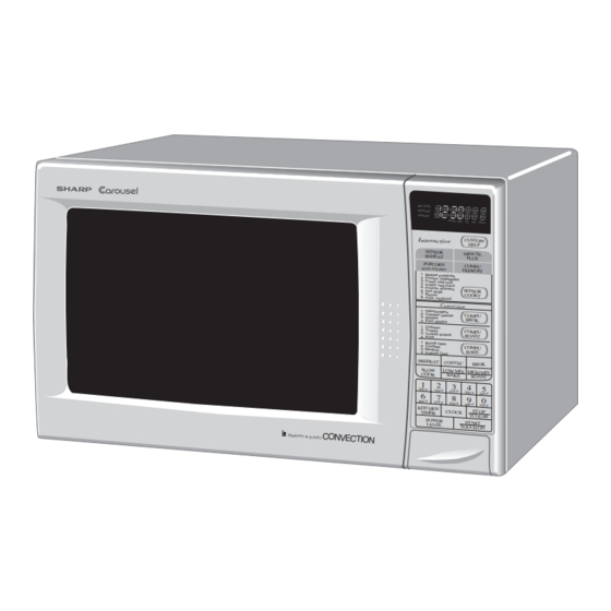
CONVECTION
MICROWAVE OVEN
R-930AK-F
R-930AW-F
This document has been published to be used for after
sales service only.
The contents are subject to change without notice.
R-930AK-F
R-930AW-F
SY526R930APWF
Page
Advertisement
Table of Contents

Related Manuals for Sharp R-930AK-F


Summary of Contents for Sharp R-930AK-F
-
Page 1: Table Of Contents
R-930AK-F R-930AW-F SERVICE MANUAL SY526R930APWF CONVECTION MICROWAVE OVEN R-930AK-F MODELS MIX CONV DEFROST SENSOR COOK LBS HELP Intera ctive CUSTOM HELP SENSOR MINUTE REHEAT PLUS R-930AW-F POPCOR N COMPU ELEVATE PKG DEFROS T 1 Baked potatoes 2 Frozen vegetabl 3 Fresh veg-soft... -
Page 2: Precautions To Be Observed Before And During Service To Avoid Possible Exposure To Excessive Microwave Energy
Before servicing an operative unit, perform a microwave emission check as per the Microwave Measurement Procedure outlined in this service manual. If microwave emissions level is in excess of the specified limit, contact SHARP ELECTRONICS CORPORATION immediately @1-800-237-4277. If the unit operates with the door open, service person should 1) tell the user not to operate the oven and 2) contact SHARP ELECTRONICS CORPORATION and Food and Drug Administration's Center for Devices and Radiological Health immediately. -
Page 3: Warning To Service Personnel
R-930AK-F R-930AW-F WARNING TO SERVICE PERSONNEL Microwave ovens contain circuitry capable of pro- ducing very high voltage and current, contact with following parts may result in a severe, possibly fatal, electrical shock. (Example) High Voltage Capacitor, High Voltage Power Trans- former, Magnetron, High Voltage Rectifier Assem- bly, High Voltage Harness etc.. -
Page 4: Microwave Measurement Procedure
R-930AK-F R-930AW-F MICROWAVE MEASUREMENT PROCEDURE A. Requirements: 1) Microwave leakage limit (Power density limit): The power density of microwave radiation emitted by a microwave oven should not exceed 1mW/cm at any point 5cm or more from the external surface of the oven, measured prior to acquisition by a... -
Page 5: Foreword And Warning
GENERAL INFORMATION R-930AK-F/ R-930AW-F FOREWORD OPERATION This Manual has been prepared to provide Sharp Electronics Corp. Service Personnel with Operation and Service Information for the SHARP CONVECTION MICROWAVE OVEN, R-930AK-F and R-930AW-F. TROUBLESHOOTING GUIDE It is recommended that service personnel carefully study the entire text of... -
Page 6: Product Specifications
R-930AK-F R-930AW-F SPECIFICATION ITEM DESCRIPTION Power Requirements 120 Volts 13.0 Amperes (Microwave) / 13.0 Amperes (Convection) 60 Hertz / Single phase, 3 wire grounded Power Output 900 watts (IEC Test Procedure) Operating frequency of 2450MHz Convection Power Output 1450 Watts Outside Dimensions Width 24-5/8"... - Page 7 R-930AK-F R-930AW-F Electrical Requirements The electrical requirements are a 115 -120 volt 60 Hz, AC only, Grounded 3-Pronged Plug Receptacle Box 15 or 20 amp. fused electrical supply. It is recommended that a separate circuit serving only this appliance be provided. When installing this appli- ance, observe all applicable codes and ordinances.
-
Page 8: Operation
(Figure O-1). switch contacts first open, and then the contacts of the primary interlock relay and the secondary interlock switch 1. The display will show "SHARP SIMPLY THE BEST PRESS close. CLEAR AND PRESS CLOCK". - Page 9 R-930AK-F R-930AW-F 4. When the oven temperature reaches the selected preheat 6-2. The heating element operates through the heater relay temperature, the following operations occur: (RY3) contacts and the power transformer operates 4-1 The heater relay is de-energized by the control unit through the primary interlock relay (RY2) contacts.
- Page 10 R-930AK-F R-930AW-F Cooking Sequence. FIRE SENSING FEATURE (MICROWAVE MODE) 1. Touch SENSOR COOK pad. This model incorporates a sensing feature which will stop the NOTE: The oven should not be operated on SENSOR oven's operation if there is a fire in the oven cavity during COOK immediately after plugging in the unit.
- Page 11 R-930AK-F R-930AW-F SCHEMATIC DIAGRAM SCHEMATIC NOTE: CONDITION OF OVEN 1. DOOR CLOSED. 2. CLOCK APPEARS ON DISPLAY. CONV. MAGNETRON TEMPERATURE THERMAL NOISE FILTER CUT-OUT FUSE FUSE POWER COM. (RY1) TRANSFORMER N.O. (RY1) CAPACITOR COM. (RY3) 0.94µ COM. 120V AC (RY2)
- Page 12 R-930AK-F R-930AW-F SCHEMATIC 1. DOOR CLOSED. 2. MIX COOKING PAD TOUCHED. 3. COOKING TIME PROGRAMMED. 4. “START” PAD TOUCHED. 5. RY2 AND RY3 WILL ALTERNATELY CLOSE. DURING COOK CYCLE. MAGNETRON CONV. THERMAL TEMPERATURE NOISE FILTER FUSE CUT-OUT FUSE COM. POWER...
- Page 13 R-930AK-F R-930AW-F activating both interlock switches. The primary interlock system Under normal operation, the temperature fuse remains closed. consists of the door sensing switch and primary interlock relay However, when abnormally high temperatures are reached located on the control circuit board.
-
Page 14: Troubleshooting Guide
R-930AK-F R-930AW-F is channelled through the cavity to remove steam and vapors 3-3. The damper is held in the closed position during the given off from the heating foods. It is then exhausted at the top of convection cooking operation. - Page 15 R-930AK-F R-930AW-F (SENSOR CONDITION OFF CONDITION COOKING CONDITION (MICROWAVE) (CONVECTION) COOKING) POSSIBLE CAUSE DEFECTIVE PARTS MAGNETRON POWER TRANSFORMER H.V. RECTIFIER ASSEMBLY HIGH VOLTAGE CAPACITOR SECONDARY INTERLOCK SWITCH PRIMARY INTERLOCK SYSTEM MONITOR SWITCH MONITOR FUSE MAGNETRON TEMPERATURE FUSE CONV. THERMAL CUT-OUT...
-
Page 16: Test Procedure
R-930AK-F R-930AW-F TEST PROCEDURES PROCEDURE COMPONENT TEST LETTER MAGNETRON ASSEMBLY TEST 1. Disconnect the power supply cord, and then remove outer case. 2. Open the door and block it open. 3. Discharge high voltage capacitor. 4. To test for an open filament, isolate the magnetron from the high voltage circuit. A continuity check across the magnetron filament leads should indicate less than 1 ohm. - Page 17 R-930AK-F R-930AW-F TEST PROCEDURES PROCEDURE COMPONENT TEST LETTER HIGH VOLTAGE RECTIFIER TEST 1. Disconnect the power supply cord, and then remove outer case. 2. Open the door and block it open. 3. Discharge high voltage capacitor. 4. Isolate the rectifier from the circuit. Using the highest ohm scale of the meter, read the resistance across the terminals and observe, reverse the leads to the rectifier terminals and observe meter reading.
- Page 18 R-930AK-F R-930AW-F TEST PROCEDURES PROCEDURE COMPONENT TEST LETTER PRIMARY INTERLOCK RELAY (RY2) 1. Disconnect the power supply cord, and then remove outer case. 2. Open the door and block it open. 3. Discharge high voltage capacitor. 4. Disconnect two (2) wire leads from the male tab terminals of the Primary Interlock Relay (RY2). Check the state of the relay contacts using a ohmmeter.
- Page 19 R-930AK-F R-930AW-F TEST PROCEDURES PROCEDURE COMPONENT TEST LETTER 4. A continuity check across the temperature fuse terminals should indicate a closed circuit unless the temperature of the magnetron reaches approximately 302˚F(150˚C). An open temperature fuse indicates overheating of the magnetron. Check for restricted air flow to the magnetron, especially the cooling duct and cooling fan.
- Page 20 R-930AK-F R-930AW-F TEST PROCEDURES PROCEDURE COMPONENT TEST LETTER 8. Reconnect the power supply cord after the outer case is installed. 9. Run the oven and check all functions. DAMPER MOTOR TEST When the power cord is plugged into the wall receptacle and 120 volts A.C. is supplied to the damper motor, the motor operates until the damper is opened and the damper switch closes.
- Page 21 R-930AK-F R-930AW-F TEST PROCEDURES PROCEDURE COMPONENT TEST LETTER NOISE FILTER TEST 1. Disconnect the power supply cord, and then remove outer case. 2. Open the door and block it open. 3. Discharge high voltage capacitor. NOISE FILTER 4. Disconnect the lead wires from the terminal the noise filter. Using an ohmmeter, check between the terminals as described in the following table.
- Page 22 R-930AK-F R-930AW-F TEST PROCEDURES PROCEDURE COMPONENT TEST LETTER a) When touching the pads, a certain group of pads do not produce a signal. b) When touching the pads, no pads produce a signal. 2-2 In connection with indicators a) At a certain digit, all or some segments do not light up.
- Page 23 R-930AK-F R-930AW-F TEST PROCEDURES PROCEDURE COMPONENT TEST LETTER Shut-off, Cook and Heater Relays Test These relays are operated by D.C. voltage Check voltage at the relay coil with a D.C. voltmeter during the microwave cooking operation or convection cooking condition.
- Page 24 R-930AK-F R-930AW-F TEST PROCEDURES PROCEDURE COMPONENT TEST LETTER 6) Reconnect all leads removed from components during testing. 7) Re-install the outer case (cabinet). 8) Reconnect the power supply cord after the outer case is installed. 9) Run the oven and check all functions.
- Page 25 R-930AK-F R-930AW-F TEST PROCEDURES PROCEDURE COMPONENT TEST LETTER (3) Close the door. (4) Touch SENSOR COOK pad and then touch the number pad 1. And touch Start pad. Now, the oven is in the sensor cooking condition and "BAKED POTATO" will appear in the display.
-
Page 26: Touch Control Panel
R-930AK-F R-930AW-F TEST PROCEDURES PROCEDURE COMPONENT TEST LETTER (18) Carry out "Water load cooking test" again and ensure that the oven works properly. Plunger Ω ± R1, R2 : 1% 1/2W Ω ± R3 : 4.3k 5% 1/4W Ω ±... - Page 27 R-930AK-F R-930AW-F DESCRIPTION OF LSI LSI(IZA797DR): The I/O signals of the LSI(IZA797DR) are detailed in the following table. Pin No. Signal Description Connected to GND. Anode (segment) of Fluorescent Display light-up voltage: -30V. Vp voltage of power source circuit input.
- Page 28 R-930AK-F R-930AW-F Pin No. Signal Description Magnetron high-voltage circuit driving signal. VARI MODE ON TIME OFF TIME P-HI (100% power) 32 sec. 0 sec. To turn on and off the cook relay(RY2). In P-90 (approx. 90% power) 30 sec. 2 sec.
- Page 29 R-930AK-F R-930AW-F Pin No. Signal Description Signal coming from touch key. When any one of G-1 line keys on key matrix is touched, a corresponding signal from P10 - P17 will be input into P27. When no key is touched, the signal is held at "L" level.
- Page 30 R-930AK-F R-930AW-F Pin No. Signal Description Segment data signal. Signal similar to P23. Key strobe signal. Signal applied to touch-key section. A pulse signal is input to P24-P27 terminal while one of G-5 line keys on key matrix is touched.
- Page 31 R-930AK-F R-930AW-F TOUCH CONTROL PANEL SERVICING 1. Precautions for Handling Electronic Components 5) Re-connect the power supply cord after the outer case is This unit uses CMOS LSI in the integral part of the circuits. installed. When handling these parts, the following precautions should 6) Run the oven and check all functions.
- Page 32 R-930AK-F R-930AW-F PRECAUTIONS FOR USING LEAD-FREE SOLDER 1. Employing lead-free solder The "Main PWB" of this model employs lead-free solder. This is indicated by the "LF" symbol printed on the PWB and in the service manual. The suffix letter indicates the alloy type of the solder.
-
Page 33: Component Replacement And Adjustment Procedure
1. Door does not close firmly. 2. Door hinge, support or latch hook is damaged. WARNING FOR WIRING To prevent an electric shock, take the following precau- 3) Sharp edge: tions. Bottom plate, Oven cavity, Waveguide flange, Chassis 1. Before wiring, support and other metallic plate. - Page 34 R-930AK-F R-930AW-F CAUTION: 1. DISCONNECT OVEN FROM POWER SUP PLY BEFORE REMOVING OUTER CASE. 2. DISCHARGE THE HIGH VOLTAGE CAPACI- TOR BEFORE TOUCHING ANY OVEN COM- PONENTS OR WIRING. NOTE: When replacing the outer case, the 2 special Torx screws must be reinstalled in the same Special screw locations.
- Page 35 R-930AK-F R-930AW-F ® POSITIVE LOCK CONNECTOR (NO-CASE TYPE) REMOVAL Terminal 1. Disconnect the power supply cord and then remove outer case. Positive lock® connector 2. Open the oven door and block it open. 3. Discharge high voltage capacitor. Push 4. Push the lever of positive lock ®...
- Page 36 R-930AK-F R-930AW-F (4) screws holding rear cabinet to bottom plate and three (3) take heating element out of heating element holders. screws holding to heater unit assembly and two (2) screws 12.Heating element is free. holding steam duct to top of oven cavity. Disconnect wire NOTE: After installed the heating element completely, leads from power supply cord terminals.
- Page 37 R-930AK-F R-930AW-F to the fan duct. CAUTION: 21. Now, the fan motor is free. Do not hit the fan blade strongly when installed because the bracket may be disfigured. INSTALLATION Make sure that the fan blade rotates smooth after 1. Install the fan motor to the fan duct with the two (2) screws installation.
- Page 38 R-930AK-F R-930AW-F 5. Disconnect wire leads from each of the switches and fuse The secondary interlock switch is in the lower position and holder. the door sensing switch is in the upper position and the 6. Remove two (2) screws holding latch hook to oven flange.
- Page 39 R-930AK-F R-930AW-F Note: The door on a microwave oven is designed to act as an electronic seal preventing the leakage of UPPER OVEN HINGE microwave energy from oven cavity during cook cycle. This function does not require that door be RE-INSTALL airtight, moisture (condensation)-tight or light-tight.
-
Page 40: Pictorial Diagram
R-930AK-F R-930AW-F Power Supply Cord... -
Page 41: Control Panel Circuit
R-930AK-F R-930AW-F... -
Page 42: Printed Wiring Board
R-930AK-F R-930AW-F (C81) R86(J8) (C80) (R45) (C45) (CN - D) (R47) (R48) (R49) (C46) (C47) (J7) (J5) (J3) (J2) (J4) (J6) CONV HEATER COM Figure S-3. Printed Wiring Board... -
Page 43: Parts List
RV-MZA222WRE0 Magnetron 1-20 RMOTDA222WRE0 Turntable motor 1-21 FDTCTA183WRK0 AH sensor assembly CABINET PARTS 2- 1 GCABUA457WRP0 Outer case cabinet [R-930AK-F] 2- 1 GCABUA721WRP0 Outer case cabinet [R-930AK-F] 2- 2 TMAPCA775WRRZ Schematic diagram 2- 3 FDAI-A198WRY0 Base cabinet 2- 3-1 GCOVHA156WRP0... - Page 44 VHEHZ161///-1 Zener diode (HZ16-1) VHEHZ5C2///-1 Zener diode (HZ5C-2) VHEHZ4A2///-1 Zener diode (HZ4A2) 3- 2 DPNLCB493WRK0 Control panel frame with key unit [R-930AK-F] 3- 2 DPNLCB439WRK0 Control panel frame with key unit [R-930AW-F] 3- 2-1 FUNTKA868WRE0 Key unit [R-930AK-F] 3- 2-1...
- Page 45 6-12 TLABHA035WRRZ Attention label SCREWS NUTS AND WASHERS 7- 1 XOTWW40P10000 Screw; 4mm x 10mm 7- 2 XOTS840P12000 Screw; 4mm x 12mm [R-930AK-F] 7- 2 XOTS740P12000 Screw; 4mm x 12mm [R-930AW-F] 7- 3 XCTWW40P08000 Screw; 4mm x 7- 4 XHTS740P08RV0 Screw;...
-
Page 46: Packing And Accessories
1. MODEL NUMBER 3. PART NO. 2. REF. NO. 4. DESCRIPTION Order Parts from the authrized SHARP parts Distributor for your area. Defective parts required return should be returned as indicated in the Service Policy. PACKING AND ACCESSORIES TOP PAD ASSEMBLY... - Page 47 R-930AK-F R-930AW-F OVEN AND CABINET PARTS...
- Page 48 R-930AK-F R-930AW-F CONTROL PANEL PARTS 7-20 3-2-1 7-20 DOOR PARTS 3-2-3 3-2-2 5-10 5-11 5-11 MISCELLANEOUS Actual wire harness may be different than illustration. '06 SHARP CORP. (1S0800E)
Need help?
Do you have a question about the R-930AK-F and is the answer not in the manual?
Questions and answers