Table of Contents
Advertisement
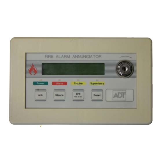
ADT-LCD40 Series
Remote Fire
Annunciators
for use with Unimode 200
Addressable Fire Alarm Control Panel
F IR E A LA R M A N N U N C IATO R
Ack
Drill
Silence
Hold 2 sec.
ADT Security Services, Inc.
One Town Center Road
Boca Raton, FL 33431
Phone: (561) 988-3600
FAX: (561) 988-3675
Rese t
Document #50520
7/25/00
Rev:
P/N 50520:D ECN 00-325
D
Advertisement
Table of Contents

Related Manuals for ADT ADT-LCD40


Summary of Contents for ADT ADT-LCD40
- Page 1 ADT Security Services, Inc. One Town Center Road Boca Raton, FL 33431 Phone: (561) 988-3600 FAX: (561) 988-3675 ADT-LCD40 Series Remote Fire Annunciators for use with Unimode 200 Addressable Fire Alarm Control Panel F IR E A LA R M A N N U N C IATO R...
-
Page 2: Fire Alarm System Limitations
While a fire alarm system may lower insurance Fire Alarm System Limitations rates, it is not a substitute for fire insurance! An automatic fire alarm system–typically made up of Heat detectors do not sense particles of combustion and smoke detectors, heat detectors, manual pull stations, alarm only when heat on their sensors increases at a audible warning devices, and a fire alarm control with predetermined rate or reaches a predetermined level. -
Page 3: Installation Precautions
Adherence to the following will aid in problem-free Installation Precautions installation with long-term reliability: WARNING - Several different sources of power can be Like all solid state electronic devices, this system may connected to the fire alarm control panel. Disconnect all operate erratically or can be damaged when subjected sources of power before servicing. - Page 4 Notes Document 50520 Rev D 7/25/00 P/N 50520:D...
-
Page 5: Table Of Contents
Table of Contents Table of Contents Section 1: ADT-LCD40 Series Annunciators ...........6 1.1 ADT-LCD40 and ADT-LCD40L ...........7 1.2 ADT-LCD40 Only ................7 Figure 1-1: Components ............8 Figure 1-2: Wiring to Terminals ...........9 1.3 SW1 DIP Switch Settings ...............10 Figure 1-3: DIP Switch Settings Example ......11 1.4 Typical Configuration ..............12 Figure 1-4: Typical Configuration ........12 Section 2: Operation ...................13... -
Page 6: Section 1: Adt-Lcd40 Series Annunciators
ADT-LCD40 Series Annunciators ADT-LCD40 Series Annunciators Section 1: FIR E A LA R M A N N U N CIATO R FIR E A L A R M A N N U N C IATO R Drill Silence Reset Hold 2 s ec. ADT-LCD40 ADT-LCD40L Note: Only Model ADT-LCD40L is listed for use in Canada. -
Page 7: Adt-Lcd40 And Adt-Lcd40L
ADT-LCD40 Series Annunciators ADT-LCD40 and ADT-LCD40L ADT-LCD40 and ADT-LCD40L • 40-character LCD display (20 characters x 2 lines) is backlit under normal and alarm conditions • System Status LEDs for Power (green), Alarm (red), Trouble (yellow) and Supervisory (yellow) • No programming necessary — duplicates messages at control panel display •... -
Page 8: Figure 1-1: Components
ADT-LCD40 Series Annunciators Components Figure 1-1: Components Note: OPEN (Up) position on SW1 OFF = Receive only is OFF state (See “Wiring to Termi- OFF = Key-switch Disable on ADT-LCD40 only nals” on page 9.). (not used on ADT-LCD40L) ON = Piezo Enable Top view Future use Membrane Connector... -
Page 9: Figure 1-2: Wiring To Terminals
ADT-LCD40 Series Annunciators Wiring to Terminals Figure 1-2: Wiring to Terminals Side view Terminal Block Terminal Block replacement replacement P/N 02108 P/N 02109 + EIA-485 OUT + EIA-485 IN - EIA-485 OUT - EIA-485 IN no connection +24 VDC IN +24 VDC OUT -24 VDC IN -24 VDC OUT... -
Page 10: Sw1 Dip Switch Settings
ADT-LCD40 Series Annunciators SW1 DIP Switch Settings SW1 DIP Switch Settings The Up position on DIP switch SW1 is the Off state. Refer to “DIP Switch Settings Example” on page 11, for an explanation of DIP switch positions. SW1 switch settings follow: 1 - On (Down) = Receive/Transmit, Off (up) = Receive Only. -
Page 11: Figure 1-3: Dip Switch Settings Example
ADT-LCD40 Series Annunciators DIP Switch Settings Example Figure 1-3: DIP Switch Settings Example Down Position = On State Up (OPEN) Position = Off State Note: SW1 DIP switch settings as illustrated in Figure 1-3 are as follows: 1. DIP switch 1: On (Down) - Receive/Transmit. This setting is used for the last or only ADT-LCD40 Series Annunciator on the EIA-485 line 2. -
Page 12: Typical Configuration
ADT-LCD40 Series Annunciators Typical Configuration Typical Configuration The ADT-LCD40 Series Annunciators mimic the Unimode 200 display, have full point-display capacity and require no programming. The ADT-LCD40 offers multiple annunciator locations with the capability of remote Acknowledge, Signal Silence, Drill and Reset functions. Figure 1-4: Typical Configuration 3,000 feet (900 m) to last device on loop Terminal Mode EIA-485 (2 wires) -
Page 13: Section 2: Operation
Operation Display Patterns Operation Section 2: Display Patterns The ADT-LCD40 Series Annunciators directly display (mimic) the information on the Unimode 200 main circuit board LCD display with the following exceptions: • Upon Power-up, the ADT-LCD40 Series may display the following message until a valid message is received from the Unimode 200 SYSTEM POWER UP WAITING FOR THE FACP... -
Page 14: Switch Functions For Adt-Lcd40 Only
Operation Switch Functions for ADT-LCD40 Only Switch Functions for ADT-LCD40 Only 2.2.1 Key-switch Key-switch (shown in Off position) The key-switch is used to enable and disable the operation of the function switches if switch 2 on DIP switch SW1 has been placed ATO R to the On (Down) position. -
Page 15: Silence
Operation Switch Functions for ADT-LCD40 Only LEDs to steady on. The second press of the switch stops the scroll- ing and holds the event on the display for one minute. Subsequent pressing of the switch 'steps' through each active event. 2.2.3 Silence When the Silence switch is pressed and released, the ADT-LCD40 sends a signal silence command to the control panel. -
Page 16: Led Indicators (All Adt-Lcd40 Series)
Operation LED Indicators (all ADT-LCD40 Series) LED Indicators (all ADT-LCD40 Series) 2.3.1 Power This is a green LED which illuminates if AC power is applied to the host FACP. The green LED will turn off if AC power to the host FACP is lost. -
Page 17: Section 3: Mounting
Mounting ADT-LCD40 Series Preparation Mounting Section 3: ADT-LCD40 Series Preparation The ADT-LCD40 Series Annunciators can be surface mounted in a three-gang electrical box such as the P/N SBB-3 (2.75" depth) or semi- flush mounted in a three-gang electrical box, P/N 10103 or equivalent, with a minimum depth of 2 3/16". -
Page 18: Figure 3-2: Hardware And Backboxes
Mounting Hardware and Backboxes Figure 3-2: Hardware and Backboxes F IRE A LA R M A NN UN C IATO R D rill A ck S ile nce R ese t Hold 2 sec. ADT-LCD40 Series flange ADT-LCD40 Series Trim Ring (replacement P/N 23165) 3-Gang Electrical Box P/N 10103 (semi-flush mount) -
Page 19: Semi-Flush Mount Backbox
Mounting Semi-flush Mount Backbox Semi-flush Mount Backbox Remove the plug-in terminal blocks from the ADT-LCD40(L) circuit board. Connect the EIA-485 and power wiring into the terminal block positions illustrated in Figure 1-1 on page 8, Figure 4-1 on page 21 and Figure 4-2 on page 22. -
Page 20: Surface Mount Backbox
Mounting Surface Mount Backbox Surface Mount Backbox Remove the plug-in terminal blocks from the ADT-LCD40(L) circuit board. Connect the EIA-485 and power wiring into the terminal block positions illustrated in Figure 1-1 on page 8, Figure 4-1 on page 21 and Figure 4-3 on page 23. -
Page 21: Section 4: Adt-Lcd40 Series Electrical Connections
ADT-LCD40 Series Electrical Connections Power Connection ADT-LCD40 Series Electrical Section 4: Connections The ADT-LCD40 Series Annunciators can be powered by the Unimode 200 24VDC nominal power or from a remote UL listed, filtered power supply such as the FCPS-24F. The power run to the annunciator must be power-limited but need not contain a power supervision relay since loss of power is inherently supervised through loss of communication with the annunciator. -
Page 22: Figure 4-2: Eia-485 Connection
ADT-LCD40 Series Electrical Connections EIA-485 Connection Figure 4-2: EIA-485 Connection ADT-LCD40 Series Terminal Block Terminal Block replacement replacement P/N 02108 P/N 02109 6,000 feet (1,800 m) maximum wire run + EIA-485 IN from source from and back to FACP (3,000 feet to last ADT-LCD40) @ 18 AWG (0.75 mm - EIA-485 IN from source EIA-485... -
Page 23: Figure 4-3: Dim-485 Connections
ADT-LCD40 Series Electrical Connections DIM-485 Connections Figure 4-3: DIM-485 Connections Circuit Board 1 2 3 4 DIM-485 CONNECTIONS DIM-485 ADT-LCD40 Series Terminal 1 - OUT (+) P1 Terminal 2 - IN (+) Terminal 2 - IN (+) P1 Terminal 1 - OUT (+) Terminal 3 - OUT (-) P1 Terminal 4 - IN (-) -
Page 24: Figure 4-4: Wiring Facp To Adt-Lcd40 Series
ADT-LCD40 Series Electrical Connections Wiring FACP to ADT-LCD40 Series Dim-485 Installation. CAUTION! Connect all wiring to the DIM-485 terminals before plugging it into connector J11 on the Unimode 200 circuit board. 1. Carefully align the DIM-485 connector with the four pins on connector J11 of the Unimode 200 2. -
Page 25: Section 5: Eia-485 Shield Termination
EIA-485 Shield Termination EIA-485 Shield Not in Conduit EIA-485 Shield Termination Section 5: The EIA-485 circuit must be wired using a twisted, shielded pair cable with a characteristic impedance of 120 ohms (+/- 20%). Do not run cable adjacent to or in the same conduit as 120 VAC service, noisy electrical circuits that are powering mechanical bells or horns, audio circuits above 25 V , motor control circuits or SCR power circuits. -
Page 26: Figure 5-1: Eia-485 Without Conduit
EIA-485 Shield Termination EIA-485 Without Conduit Figure 5-1: EIA-485 Without Conduit Connect the drain wire to the outside of the Unimode 200 cabinet via a BX- type connector. Shield Drain Wire (+) EIA-485 (-) EIA-485 FACP Backbox FACP Document 50520 Rev D 7/25/00 P/N 50520:D... -
Page 27: Eia-485 Shield In Full Conduit
EIA-485 Shield Termination EIA-485 Shield in Full Conduit EIA-485 Shield in Full Conduit The EIA-485 line allows the FACP to communicate with the ADT-LCD40 Series Annunciators. The shield for the EIA-485 line must be connected to earth ground at the FACP (both exiting and entering the FACP) but must be left floating (no connection) at the annunciator if it is the first or only device on the EIA-485 line. -
Page 28: Section 6: Programming The Unimode 200
Programming the Unimode 200 EIA-485 In Conduit Programming the Unimode 200 Section 6: The Unimode 200 must be programmed to allow use of the ADT-LCD40 Series Annunciators. In order to program the Unimode 200, make certain the main circuit board 'Write Protect' switch (SW1) is in the down position and then press the ENTER key on the panel key- pad. - Page 29 Index 6, 7, 12, 14 Acknowledge switch 6, 7, 10, 14, 15 ADT-LCD40 see also ADT-LCD40 Series Annunciators software version 6, 12, 13, 16, 17, 19, 20, 21, 22, ADT-LCD40 Series Annunciators 23, 28 ADT-LCD40 Series Annunciators display custom alpha labels device type point alarm supervisory...
- Page 30 wiring DIM-485 module 8, 10, 11 DIP Switch settings function switches piezo sounder 10, 11 Receive/Transmit DIP switches 14, 19, 20 display 14, 15 scroll step through 7, 12, 22 distance from panel 6, 7, 12, 14, 15 Drill switch 9, 17, 25, 27 earth ground 6, 7, 12, 19, 22, 25, 26, 27...
- Page 31 Liquid Crystal Display 8, 10 Local Authority Having Jurisdiction Manual Evacuate 7, 17, 19 mounting semi-flush 7, 20 surface see also Notification Appliance Circuit nonresettable Operation 7, 15 piezo sounder alarm resound 8, 10, 11 enable/disable silence trouble resound power connection 6, 7, 16 Power LED 6, 9, 12, 21...
- Page 32 6, 14, 15 Silence switch software version ADT-LCD40 Unimode 200 static static protection 21, 22 supervised 6, 7, 16 Supervisory LED 7, 20 surface mount SW1 DIP Switch switch functions 14, 15, 16 System LEDs System Reset switch 6, 7 System Status LEDs 7, 9, 19, 20 terminal block...
- Page 33 Notes Document 50520 Rev D 7/25/00 P/N 50520:D...
- Page 34 Notes Document 50520 Rev D 7/25/00 P/N 50520:D...
- Page 35 Notes Document 50520 Rev D 7/25/00 P/N 50520:D...
Need help?
Do you have a question about the ADT-LCD40 and is the answer not in the manual?
Questions and answers