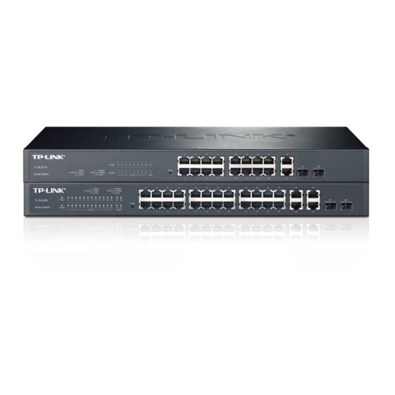
TP-Link TL-SL2218 User Manual
Smart switch
Hide thumbs
Also See for TL-SL2218:
- Installation manual (28 pages) ,
- Reference manual (166 pages) ,
- User manual (160 pages)
Table of Contents
Advertisement
Quick Links
Advertisement
Table of Contents

Related Manuals for TP-Link TL-SL2218


Summary of Contents for TP-Link TL-SL2218
- Page 1 TL-SL2218/TL-SL2428 Smart Switch Rev: 1.1.0 1910010753...
-
Page 2: Fcc Statement
Specifications are subject to change without notice. is a registered trademark of TP-LINK TECHNOLOGIES CO., LTD. Other brands and product names are trademarks or registered trademarks of their respective holders. No part of the specifications may be reproduced in any form or by any means or used to make any derivative such as translation, transformation, or adaptation without permission from TP-LINK TECHNOLOGIES CO., LTD. -
Page 3: Safety Information
Safety Information When product has power button, the power button is one of the way to shut off the product; When there is no power button, the only way to completely shut off power is to disconnect the product or the power adapter from the power source. Don’t disassemble the product, or make repairs yourself. -
Page 4: Table Of Contents
CONTENTS Package Contents ..........................1 Chapter 1 About this Guide ......................2 Intended Readers ......................2 Conventions........................2 Overview of This Guide ....................2 Chapter 2 Introduction ........................5 Overview of the Switch ....................5 Main Features.......................5 Appearance Description ....................5 2.3.1 Front Panel ......................5 2.3.2 Rear Panel ......................7 Chapter 3 Login to the Switch.......................8 Login..........................8 Configuration ........................8... - Page 5 5.1.3 Port Security ....................27 5.1.4 Port Isolation ....................29 LAG ..........................30 5.2.1 LAG Table ......................30 5.2.2 Static LAG ......................32 Traffic Monitor ......................33 5.3.1 Traffic Summary....................33 5.3.2 Traffic Statistics ....................34 MAC Address......................36 5.4.1 Address Table ....................36 5.4.2 Static Address ....................38 5.4.3 Dynamic Address .....................39 5.4.4 Filtering Address ....................41 Chapter 6 VLAN .........................43...
- Page 6 8.1.3 VLAN Config ....................78 8.1.4 Multicast VLAN ....................80 Multicast IP .........................83 8.2.1 Multicast IP Table .....................84 8.2.2 Static Multicast IP.....................84 Multicast Filter......................85 8.3.1 IP-Range......................86 8.3.2 Port Filter ......................87 Packet Statistics......................88 Chapter 9 QoS..........................90 DiffServ ........................93 9.1.1 Port Priority ......................93 9.1.2 802.1P Priority ....................94 9.1.3 DSCP Priority....................95...
- Page 7 11.2.1 Log Table .......................121 11.2.2 Local Log .......................122 11.2.3 Remote Log ....................122 11.2.4 Backup Log ....................123 11.3 Device Diagnostics ....................124 11.3.1 Cable Test ......................124 11.3.2 Loopback .......................125 11.4 Network Diagnostics ....................126 11.4.1 Ping........................126 11.4.2 Tracert......................127 Appendix A: Specifications ......................128 Appendix B: Configuring the PCs ....................129 Appendix C: Glossary........................132...
-
Page 8: Package Contents
The following items should be found in your box: One TL-SL2218 /TL-SL2428 Smart Switch One power cord Two mounting brackets and other fittings Installation Guide Resource CD for TL-SL2218 /TL-SL2428 Smart Switch, including: • This User Guide • Other Helpful Information Note: Make sure that the package contains the above items. -
Page 9: Chapter 1 About This Guide
1.2 Conventions In this Guide the following conventions are used: The two devices of TL-SL2218 and TL-SL2428 are sharing this User Guide. For simplicity, we will take TL-SL2428 for example throughout the configuration chapters. TL-SL2218 and TL-SL2428 just differ in the number of LED indicators and ports and all figures in this guide are of TL-SL2428. - Page 10 Chapter Introduction Chapter 4 System This module is used to configure system properties of the switch. Here mainly introduces: System Info: Configure the description, system time, Daylight Saving Time and network parameters of the switch. User Management: Configure the user name and password for users to log on to the Web management page with a certain access level.
- Page 11 Chapter Introduction Chapter 9 QoS This module is used to configure QoS function to provide different quality service various network applications requirements. Here mainly introduces: DiffServ: Configure priorities, port priority, 802.1P priority and DSCP priority. Bandwidth Control: Configure rate limit feature to control the traffic rate on each port;...
-
Page 12: Chapter 2 Introduction
RMON, Log-in bring abundant management policies. TL-SL2218/TL-SL2428 Switch integrate multiple functions with excellent performance, and are friendly to manage, which can fully meet the need of the users demanding higher networking performance. 2.2 Main Features • Resiliency and Availability + IEEE 802.1s Multiple Spanning Tree provides high link availability in multiple VLAN environments. - Page 13 Figure 2-1 Front Panel of TL-SL2218 The front panel of TL-SL2428 is shown as Figure 2-2. Figure 2-2 Front Panel of TL-SL2428 The following parts are located on the front panel of the Switch: Reset: With the Switch powered on, press Reset button for five seconds to reset the software setting to its factory default settings.
-
Page 14: Rear Panel
2.3.2 Rear Panel The rear panel of TL-SL2218/TL-SL2428 features a power socket and a Grounding Terminal (marked with ). The rear panel of TL-SL2218 is shown as the following figure. Figure 2-3 Rear Panel of TL-SL2218 The rear panel of TL-SL2428 is shown as the following figure. -
Page 15: Chapter 3 Login To The Switch
Chapter 3 Login to the Switch 3.1 Login 1) To access the configuration utility, open a web-browser and type in the default address http://192.168.0.1 in the address field of the browser, then press the Enter key. Figure 3-1 Web-browser Tips: To log in to the Switch, the IP address of your PC should be set in the same subnet addresses of the Switch. - Page 16 Figure 3-3 Main Setup-Menu Note: Clicking Apply can only make the new configurations effective before the switch is rebooted. If you want to keep the configurations effective even the switch is rebooted, please click Save Config. You are suggested to click Save Config before cutting off the power or rebooting the switch to avoid losing the new configurations.
-
Page 17: Chapter 4 System
Chapter 4 System The System module is mainly for system configuration of the switch, including four submenus: System Info, User Management, System Tools and Access Security. 4.1 System Info The System Info, mainly for basic properties configuration, can be implemented on System Summary, Device Description, System Time, Daylight Saving Time and System IP pages. - Page 18 Indicates the 1000Mbps port is not connected to a device. Indicates the 1000Mbps port is at the speed of 1000Mbps. Indicates the 1000Mbps port is at the speed of 10Mbps or 100Mbps. Indicates the SFP port is not connected to a device. Indicates the SFP port is at the speed of 1000Mbps.
-
Page 19: Device Description
Figure 4-3 Bandwidth Utilization Bandwidth Utilization Select Rx to display the bandwidth utilization of receiving packets on this port. Select Tx to display the bandwidth utilization of sending packets on this port. 4.1.2 Device Description On this page you can configure the description of the switch, including device name, device location and system contact. -
Page 20: System Time
Device Location: Enter the location of the switch. System Contact: Enter your contact information. 4.1.3 System Time System Time is the time displayed while the switch is running. On this page you can configure the system time and the settings here will be used for other time-based functions like ACL. You can manually set the system time, or synchronize with PC’s clock as the system time. - Page 21 Figure 4-6 System Time The following entries are displayed on this screen: DST Status: Enable or Disable the DST. Predefined Mode: Select a predefined DST configuration. USA: First Sunday in April, 02:00 ~ Last Sunday in October, 02:00. Australia: First Sunday in October, 02:00 ~ First Sunday in April, 03:00.
-
Page 22: System Ip
4.1.5 System IP Each device in the network possesses a unique IP Address. You can log on to the Web management page to operate the switch using this IP Address. The switch supports three modes to obtain an IP address: Static IP, DHCP and BOOTP. The IP address obtained using a new mode will replace the original IP address. -
Page 23: User Management
Note: Changing the IP address to a different IP segment will interrupt the network communication, so please keep the new IP address in the same IP segment with the local network. The switch only possesses an IP address. The IP address configured will replace the original IP address. - Page 24 Figure 4-9 User Config The following entries are displayed on this screen: User Info User Name: Create a name for users’ login. Access Level: Select the access level to login. Admin: Admin can edit, modify and view all the settings of different functions.
-
Page 25: System Tools
4.3 System Tools The System Tools function, allowing you to manage the configuration file of the switch, can be implemented on Config Restore, Config Backup, Firmware Upgrade, System Reboot and System Reset pages. 4.3.1 Config Restore On this page you can upload a backup configuration file to restore your switch to this previous configuration. -
Page 26: Firmware Upgrade
4.3.3 Firmware Upgrade The switch system can be upgraded via the Web management page. To upgrade the system is to get more functions and better performance. Go to http://www.tp-link.com to download the updated firmware. Choose the menu System→System Tools→Firmware Upgrade to load the following page. -
Page 27: System Reboot
To avoid damage, please don't turn off the device while upgrading. After upgrading, the device will reboot automatically. You are suggested to backup the configuration before upgrading. 4.3.4 System Reboot On this page you can reboot the switch and return to the login page. Please save the current configuration before rebooting to avoid losing the configuration unsaved. - Page 28 Figure 4-15 Access Control The following entries are displayed on this screen: Access Control Config Control Mode: Select the control mode for users to log on to the Web management page. IP-based: Select this option to limit the IP-range of the users for login.
- Page 29 Session Config Session Timeout: If you do nothing with the Web management page within the timeout time, the system will log out automatically. If you want to reconfigure, please login again. Access User Number Select Enable/Disable the Number Control function. Number Control;...
-
Page 30: Chapter 5 Switching
Chapter 5 Switching Switching module is used to configure the basic functions of the switch, including four submenus: Port, LAG, Traffic Monitor and MAC Address. 5.1 Port The Port function, allowing you to configure the basic features for the port, is implemented on the Port Config, Port Mirror, Port Security and Port Isolation pages. -
Page 31: Port Mirror
Port: Displays the port number. Description: Give a description to the port for identification. Status: Allows you to Enable/Disable the port. When Enable is selected, the port can forward the packets normally. Speed and Duplex: Select the Speed and Duplex mode for the port. The device connected to the switch should be in the same Speed and Duplex mode with the switch. - Page 32 Figure 5-2 Mirroring Port The following entries are displayed on this screen. Mirror Group List Group: Displays the mirror group number. Mirroring: Displays the mirroring port number. Mode: Displays the mirror mode, the value will be "Ingress" or "Egress", Mirrored Port: Displays the mirrored ports.
- Page 33 Figure 5-3 Mirroring Port The following entries are displayed on this screen. Mirror Group Number: Select the mirror group number you want to configure. Mirroring Port Mirroring Port: Select the mirroring port number. Mirrored Port Port Select: Click the Select button to quick-select the corresponding port based on the port number you entered.
-
Page 34: Port Security
Egress: Select Enable/Disable the Egress feature. When the Egress is enabled, the outgoing packets sent by the mirrored port will be copied to the mirroring port. LAG: Displays the LAG number which the port belongs to. The LAG member can not be selected as the mirrored port or mirroring port. Note: The LAG member can not be selected as the mirrored port or mirroring port. - Page 35 Figure 5-4 Port Security The following entries are displayed on this screen: Port Security Select: Select the desired port for Port Security configuration. It is multi-optional. Port: Displays the port number. Max Learned MAC: Specify the maximum number of MAC addresses that can be learned on the port.
-
Page 36: Port Isolation
Note: The Port Security function is disabled for the LAG port member. Only the port is removed from the LAG, will the Port Security function be available for the port. 5.1.4 Port Isolation Port Isolation provides a method of restricting traffic flow to improve the network security by forbidding the port to forward packets to the ports that are not on its forward portlist. -
Page 37: Lag
Port Isolation List Port: Display the port number. Forward Portlist: Display the forwardlist. 5.2 LAG LAG (Link Aggregation Group) is to combine a number of ports together to make a single high-bandwidth data path, so as to implement the traffic load sharing among the member ports in the group and to enhance the connection reliability. - Page 38 Figure 5-6 LAG Table The following entries are displayed on this screen: Global Config Hash Algorithm: Select the applied scope of Aggregate Arithmetic, which results in choosing a port to transfer the packets. • SRC MAC + DST MAC: When this option is selected, the Aggregate Arithmetic will apply to the source and destination MAC addresses of the packets.
-
Page 39: Static Lag
Figure 5-7 Detail Information 5.2.2 Static LAG On this page, you can manually configure the LAG. Choose the menu Switching→LAG→Static LAG to load the following page. Figure 5-8 Static LAG The following entries are displayed on this screen: LAG Config Group Number: Select a Group Number for the LAG. -
Page 40: Traffic Monitor
Member Port Member Port: Select the port as the LAG member. Clearing all the ports of the LAG will delete this LAG. Tips: The LAG can be deleted by clearing its all member ports. 5.3 Traffic Monitor The Traffic Monitor function, monitoring the traffic of each port, is implemented on the Traffic Summary and Traffic Statistics pages. -
Page 41: Traffic Statistics
Refresh Rate: Enter a value in seconds to specify the refresh interval. Traffic Summary Port Select: Click the Select button to quick-select the corresponding port based on the port number you entered. Port: Displays the port number. Packets Rx: Displays the number of packets received on the port. The error packets are not counted in. - Page 42 The following entries are displayed on this screen: Auto Refresh Auto Refresh: Allows you to Enable/Disable refreshing the Traffic Summary automatically. Refresh Rate: Enter a value in seconds to specify the refresh interval. Statistics Port: Enter a port number and click the Select button to view the traffic statistics of the corresponding port.
-
Page 43: Mac Address
5.4 MAC Address The main function of the switch is forwarding the packets to the correct ports based on the destination MAC address of the packets. Address Table contains the port-based MAC address information, which is the base for the switch to forward packets quickly. The entries in the Address Table can be updated by auto-learning or configured manually. - Page 44 Figure 5-11 Address Table The following entries are displayed on this screen: Search Option MAC Address: Enter the MAC address of your desired entry. VLAN ID: Enter the VLAN ID of your desired entry. Port: Select the corresponding port number of your desired entry. Type: Select the type of your desired entry.
-
Page 45: Static Address
5.4.2 Static Address The static address table maintains the static address entries which can be added or removed manually, independent of the aging time. In the stable networks, the static MAC address entries can facilitate the switch to reduce broadcast packets and remarkably enhance the efficiency of packets forwarding without learning the address. -
Page 46: Dynamic Address
Static Address Table Select: Select the entry to delete or modify the corresponding port number. It is multi-optional. MAC Address: Displays the static MAC Address. VLAN ID: Displays the corresponding VLAN ID of the MAC address. Port: Displays the corresponding Port number of the MAC address. Here you can modify the port number to which the MAC address is bound. - Page 47 Figure 5-13 Dynamic Address The following entries are displayed on this screen: Aging Config Auto Aging: Allows you to Enable/Disable the Auto Aging feature. Aging Time: Enter the Aging Time for the dynamic address. Search Option Search Option: Select a Search Option from the pull-down list and click the Search button to find your desired entry in the Dynamic Address Table.
-
Page 48: Filtering Address
Type: Displays the Type of the MAC address. Aging Status: Displays the Aging Status of the MAC address. Bind: Click the Bind button to bind the MAC address of your selected entry to the corresponding port statically. Tips: Setting aging time properly helps implement effective MAC address aging. The aging time that is too long or too short results decreases the performance of the switch. - Page 49 VLAN ID: Enter the corresponding VLAN ID of the MAC address. Search Option Search Option: Select a Search Option from the pull-down list and click the Search button to find your desired entry in the Filtering Address Table. • MAC: Enter the MAC address of your desired entry. •...
-
Page 50: Chapter 6 Vlan
Chapter 6 VLAN The traditional Ethernet is a data network communication technology basing on CSMA/CD (Carrier Sense Multiple Access/Collision Detect) via shared communication medium. Through the traditional Ethernet, the overfull hosts in LAN will result in serious collision, flooding broadcasts, poor performance or even breakdown of the Internet. -
Page 51: Q Vlan
matched, the switch will add a corresponding VLAN tag to it and forward it in the corresponding VLAN. 6.1 802.1Q VLAN VLAN tags in the packets are necessary for the switch to identify packets of different VLANs. The switch works at the data link layer in OSI model and it can identify the data link layer encapsulation of the packet only, so you can add the VLAN tag field into the data link layer encapsulation for identification. - Page 52 (2) TRUNK: The TRUNK port can be added in multiple VLANs, and the egress rule of the port is TAG. The TRUNK port is generally used to connect the cascaded network devices for it can receive and forward the packets of multiple VLANs. When the packets are forwarded by the TRUNK port, its VLAN tag will not be changed.
-
Page 53: Vlan Config
6.1.1 VLAN Config On this page, you can view the current created 802.1Q VLAN. Choose the menu VLAN→802.1Q VLAN→VLAN Config to load the following page. Figure 6-3 VLAN Table To ensure the normal communication of the factory switch, the default VLAN of all ports is set to VLAN1. - Page 54 Figure 6-4 Create or Modify 802.1Q VLAN The following entries are displayed on this screen: VLAN Config VLAN ID: Enter the ID number of VLAN. Description: Give a description to the VLAN for identification. VLAN Members Port Select: Click the Select button to quick-select the corresponding entry based on the port number you entered.
-
Page 55: Port Config
Egress Rule: Select the Egress Rule for the VLAN port member. The default egress rule is UNTAG. • TAG: All packets forwarded by the port are tagged. The packets contain VLAN information. • UNTAG: Packets forwarded by the port are untagged. LAG: Displays the LAG to which the port belongs. - Page 56 Select the Link Type from the pull-down list for the port. Link Type: • ACCESS: The ACCESS port can be added in a single VLAN, and the egress rule of the port is UNTAG. The PVID is same as the current VLAN ID. If the current VLAN is deleted, the PVID will be set to 1 by default.
-
Page 57: Application Example For 802.1Q Vlan
Configuration procedure: Step Operation Description Set the link type for Required. On the VLAN→802.1Q VLAN→Port Config page, set port. the link type for the port basing on its connected device. Create VLAN. Required. On the VLAN→802.1Q VLAN→VLAN Config page, click the Create button to create a VLAN. Enter the VLAN ID and the description for the VLAN. - Page 58 Configuration Procedure Configure Switch A Step Operation Description Configure Required. On VLAN→802.1Q VLAN→Port Config page, configure Link Type of the the link type of Port 2, Port 3 and Port 4 as ACCESS, TRUNK and ports ACCESS respectively Create VLAN10 Required.
-
Page 59: Chapter 7 Spanning Tree
Chapter 7 Spanning Tree STP (Spanning Tree Protocol), subject to IEEE 802.1D standard, is to disbranch a ring network in the Data Link layer in a local network. Devices running STP discover loops in the network and block ports by exchanging information, in that way, a ring network can be disbranched to form a tree-topological ring-free network to prevent packets from being duplicated and forwarded endlessly in the network. - Page 60 Port: Port 3 is the root port of switch B and port 5 is the root port of switch C; port 1 is the designated port of switch A and port 4 is the designated port of switch B; port 6 is the blocked port of switch C.
- Page 61 STP Generation In the beginning In the beginning, each switch regards itself as the root, and generates a configuration BPDU for each port on it as a root, with the root path cost being 0, the ID of the designated bridge being that of the switch, and the designated port being itself.
- Page 62 Tips: In a STP with stable topology, only the root port and designated port can forward data, and the other ports are blocked. The blocked ports only can receive BPDUs. RSTP (Rapid Spanning Tree Protocol), evolved from the 802.1D STP standard, enable Ethernet ports to transit their states rapidly.
- Page 63 Figure 7-2 Basic MSTP diagram MSTP MSTP divides a network into several MST regions. The CST is generated between these MST regions, and multiple spanning trees can be generated in each MST region. Each spanning tree is called an instance. As well as STP, MSTP uses BPDUs to generate spanning tree. The only difference is that the BPDU for MSTP carries the MSTP configuration information on the switches.
-
Page 64: Stp Config
Figure 7-3 Port roles The Spanning Tree module is mainly for spanning tree configuration of the switch, including four submenus: STP Config, Port Config, MSTP Instance and STP Security. 7.1 STP Config The STP Config function, for global configuration of spanning trees on the switch, can be implemented on STP Config and STP Summary pages. - Page 65 Figure 7-4 STP Config The following entries are displayed on this screen: Global Config STP: Select Enable/Disable STP function globally on the switch. Version: Select the desired STP version on the switch. STP: Spanning Tree Protocol. RSTP: Rapid Spanning Tree Protocol. MSTP: Multiple Spanning Tree Protocol.
-
Page 66: Stp Summary
5pps. Max Hops: Enter a value from 1 to 40 to set the maximum number of hops that occur in a specific region before the BPDU is discarded. The default value is 20 hops. Note: The forward delay parameter and the network diameter are correlated. A too small forward delay parameter may result in temporary loops. -
Page 67: Port Config
Figure 7-5 STP Summary 7.2 Port Config On this page you can configure the parameters of the ports for CIST Choose the menu Spanning Tree→Port Config to load the following page. - Page 68 Figure 7-6 Port Config The following entries are displayed on this screen: Port Config Port Select: Click the Select button to quick-select the corresponding port based on the port number you entered. Select: Select the desired port for STP configuration. It is multi-optional. Port: Displays the port number of the switch.
-
Page 69: Mstp Instance
Root Port: Indicates the port that has the lowest path cost from this bridge to the Root Bridge and forwards packets to the root. Designated Port: Indicates the port that forwards packets to a downstream network segment or switch. Master Port: Indicates the port that connects a MST region to the common root. -
Page 70: Instance Config
Figure 7-7 Region Config The following entries are displayed on this screen: Region Config Region Name: Create a name for MST region identification using up to 32 characters. Revision: Enter the revision from 0 to 65535 for MST region identification. 7.3.2 Instance Config Instance Configuration, a property of MST region, is used to describe the VLAN to Instance mapping configuration. -
Page 71: Instance Port Config
The following entries are displayed on this screen: Instance Table Instance ID Select: Click the Select button to quick-select the corresponding Instance ID based on the ID number you entered. Select: Select the desired Instance ID for configuration. It is multi-optional. Instance: Displays Instance ID of the switch. - Page 72 Figure 7-9 Instance Port Config The following entries are displayed on this screen: Port Config Instance ID: Select the desired instance ID for its port configuration. Port Select: Click the Select button to quick-select the corresponding port based on the port number you entered. Select: Select the desired port to specify its priority and path cost.
-
Page 73: Stp Security
LAG: Displays the LAG number which the port belongs to. Note: The port status of one port in different spanning tree instances can be different. Global configuration Procedure for Spanning Tree function: Step Operation Description Make clear roles the switches Preparation. - Page 74 packets from the upstream switch and spanning trees are regenerated, and thereby loops can be prevented. Root Protect A CIST and its secondary root bridges are usually located in the high-bandwidth core region. Wrong configuration or malicious attacks may result in configuration BPDU packets with higher priorities being received by the legal root bridge, which causes the current legal root bridge to lose its position and network topology jitter to occur.
- Page 75 Figure 7-10 Port Protect The following entries are displayed on this screen: Port Protect Port Select: Click the Select button to quick-select the corresponding port based on the port number you entered. Select: Select the desired port for port protect configuration. It is multi-optional.
-
Page 76: Tc Protect
7.4.2 TC Protect When TC Protect is enabled for the port on Port Protect page, the TC threshold and TC protect cycle need to be configured on this page. Choose the menu Spanning Tree→STP Security→TC Protect to load the following page. Figure 7-11 TC Protect The following entries are displayed on this screen: TC Protect... - Page 77 On Spanning Tree→STP Config→Port Config page, enable MSTP function for the port. Configure the region name and On Spanning Tree→MSTP Instance→Region Config the revision of MST region page, configure the region as TP-LINK and keep the default revision setting. Configure VLAN-to-Instance Spanning Tree→MSTP...
- Page 78 On Spanning Tree→STP Config→Port Config page, enable MSTP function for the port. Configure the region name and On Spanning Tree→MSTP Instance→Region Config the revision of MST region page, configure the region as TP-LINK and keep the default revision setting. Configure VLAN-to-Instance Spanning Tree→MSTP...
- Page 79 The topology diagram of the two instances after the topology is stable For Instance 1 (VLAN 101, 103 and 105), the red paths in the following figure are connected links; the gray paths are the blocked links. For Instance 2 (VLAN 102, 104 and 106), the blue paths in the following figure are connected links;...
-
Page 80: Chapter 8 Multicast
Chapter 8 Multicast Multicast Overview In the network, packets are sent in three modes: unicast, broadcast and multicast. In unicast, the source server sends separate copy information to each receiver. When a large number of users require this information, the server must send many pieces of information with the same content to the users. - Page 81 4. Real time is highly demanded and certain packets drop is allowed. Multicast Address 1. Multicast IP Address: As specified by IANA (Internet Assigned Numbers Authority), Class D IP addresses are used as destination addresses of multicast packets. The multicast IP addresses range from 224.0.0.0~239.255.255.255.
-
Page 82: Igmp Snooping
should be a group port list, so the switch will duplicate this multicast data and deliver each port one copy. The general format of the multicast address table is described as Figure 8-3 below. VLAN ID Multicast IP Port Figure 8-3 Multicast Address Table IGMP Snooping In the network, the hosts apply to the near Router for joining (leaving) a multicast group by sending IGMP (Internet Group Management Protocol) messages. -
Page 83: Snooping Config
When receiving IGMP report message, the switch will send the report message via the router port in the VLAN as well as analyze the message to get the address of the multicast group the host applies for joining. The receiving port will be processed: if the receiving port is a new member port, it will be added to the multicast address table with its member port time specified;... -
Page 84: Port Config
Figure 8-4 Basic Config The following entries are displayed on this screen: Global Config IGMP Snooping: Select Enable/Disable IGMP Snooping function globally on the Switch. Unknown Multicast: Select the operation for the switch to process unknown multicast, Forward or Discard. IGMP Snooping Status Description: Displays IGMP Snooping status. -
Page 85: Vlan Config
Figure 8-5 Port Config The following entries are displayed on this screen: Port Config Port Select: Click the Select button to quick-select the corresponding port based on the port number you entered. Select: Select the desired port for IGMP Snooping feature configuration. It is multi-optional. - Page 86 Choose the menu Multicast→IGMP Snooping→VLAN Config to load the following page. Figure 8-6 VLAN Config The following entries are displayed on this screen: VLAN Config VLAN ID: Enter the VLAN ID to enable IGMP Snooping for the desired VLAN. Router Port Time: Specify the aging time of the router port.
-
Page 87: Multicast Vlan
Member Port Time: Displays the member port time of the VLAN. Leave Time: Displays the leave time of the VLAN. Router Port: Displays the router port of the VLAN. Note: The settings here will be invalid when multicast VLAN is enabled Configuration procedure: Step Operation Description... - Page 88 Figure 8-7 Multicast VLAN The following entries are displayed on this screen: Multicast VLAN Multicast VLAN: Select Enable/Disable Multicast VLAN feature. VLAN ID: Enter the VLAN ID of the multicast VLAN. Router Port Time: Specify the aging time of the router port. Within this time, if the switch doesn’t receive IGMP query message from the router port, it will consider this port is not a router port any more.
- Page 89 After a multicast VLAN is created, all the IGMP packets will be processed only within the multicast VLAN. Configuration procedure: Step Operation Description Enable IGMP Snooping Required. Enable IGMP Snooping globally on the switch function port Multicast→IGMP Snooping→Snooping Config and Port Config page. Create a multicast VLAN Required.
-
Page 90: Multicast Ip
Configuration Procedure Step Operation Description Create VLANs Create three VLANs with the VLAN ID 3, 4 and 5 respectively, and specify the description of VLAN3 as Multicast VLAN on VLAN→802.1Q VLAN page. Configure ports On VLAN→802.1Q VLAN function pages. For port 3, configure its link type as GENERAL and its egress rule as TAG, and add it to VLAN3, VLAN4 and VLAN5. -
Page 91: Multicast Ip Table
8.2.1 Multicast IP Table On this page you can view the multicast IP table on the switch. Choose the menu Multicast→Multicast IP→Multicast IP Table to load the following page. Figure 8-8 Multicast IP Table The following entries are displayed on this screen: Search Option Multicast IP: Enter the multicast IP address the desired entry must carry. -
Page 92: Multicast Filter
Choose the menu Multicast→Multicast IP→Static Multicast IP to load the following page. Figure 8-9 Static Multicast IP Table The following entries are displayed on this screen: Create Static Multicast Multicast IP: Enter static multicast IP address. VLAN ID: Enter the VLAN ID of the multicast IP. Forward Port: Enter the forward port of the multicast group. -
Page 93: Ip-Range
When applying for a multicast group, the host will send IGMP report message. After receiving the report message, the switch will firstly check the multicast filter rules configured for the receiving port. If the port can be added to the multicast group, it will be added to the multicast address table; if the port can not be added to the multicast group, the switch will drop the IGMP report message. -
Page 94: Port Filter
8.3.2 Port Filter On this page you can configure the multicast filter rules for port. Take the configuration on this page and the configuration on IP-Range page together to function to implement multicast filter function on the switch. Choose the menu Multicast→Multicast Filter→Port Filter to load the following page. Figure 8-11 Port Filter The following entries are displayed on this screen: Port Filter Config... -
Page 95: Packet Statistics
LAG: Displays the LAG number which the port belongs to. Note: Multicast Filter feature can only have effect on the VLAN with IGMP Snooping enabled. Multicast Filter feature has no effect on static multicast IP. Up to 15 IP-Ranges can be bound to one port. Configuration Procedure: Step Operation Description... - Page 96 The following entries are displayed on this screen: Auto Refresh Auto Refresh: Select Enable/Disable auto refresh feature. Refresh Period: Enter the time from 3 to 300 in seconds to specify the auto refresh period. IGMP Statistics Port Select: Click the Select button to quick-select the corresponding port based on the port number you entered.
-
Page 97: Chapter 9 Qos
Chapter 9 QoS QoS (Quality of Service) functions to provide different quality of service for various network applications and requirements and optimize the bandwidth resource distribution so as to provide a network service experience of a better quality. This switch classifies the ingress packets, maps the packets to different priority queues and then forwards the packets according to specified scheduling algorithms to implement QoS function. - Page 98 2. 802.1P Priority Figure 9-2 802.1Q frame As shown in the figure above, each 802.1Q Tag has a Pri field, comprising 3 bits. The 3-bit priority field is 802.1p priority in the range of 0 to 7. 802.1P priority determines the priority of the packets based on the Pri value.
- Page 99 Figure 9-4 SP-Mode WRR-Mode: Weight Round Robin Mode. In this mode, packets in all the queues are sent in order based on the weight value for each queue and every queue can be assured of a certain service time. The weight value indicates the occupied proportion of the resource. WRR queue overcomes the disadvantage of SP queue that the packets in the queues with lower priority can not get service for a long time.
-
Page 100: Diffserv
Equ-Mode: Equal-Mode. In this mode, all the queues occupy the bandwidth equally. The weight value ratio of all the queues is 1:1:1:1. The QoS module is mainly for traffic control and priority configuration, including two submenus: DiffServ and Bandwidth Control. 9.1 DiffServ This switch classifies the ingress packets, maps the packets to different priority queues and then forwards the packets according to specified scheduling algorithms to implement QoS function. -
Page 101: P Priority
Priority: Specify the priority for the port. LAG: Displays the LAG number which the port belongs to. Note: To complete QoS function configuration, you have to go to the Schedule Mode page to select a schedule mode after the configuration is finished on this page. Configuration Procedure: Step Operation Description... -
Page 102: Dscp Priority
802.1P Priority Config 802.1P Priority: Select Enable/Disable 802.1P Priority. Priority Level Tag-id/CoS-id: Indicates the precedence level defined by IEEE802.1P and the CoS ID Queue TC-id: Indicates the priority level of egress queue the packets with tag and CoS-id are mapped to. The priority levels of egress queue are labeled as TC0, TC1, TC2 and TC3 Note: To complete QoS function configuration, you have to go to the Schedule Mode page to select a... - Page 103 Figure 9-8 DSCP Priority The following entries are displayed on this screen: DSCP Priority Config DSCP Priority: Select Enable or Disable DSCP Priority. Priority Level DSCP: Indicates the priority determined by the DS region of IP datagram. It ranges from 0 to 63. Priority Level: Indicates the priority level the packets with tag are mapped to.
-
Page 104: Schedule Mode
Configuration procedure: Step Operation Description Log on to the DSCP Priority page Enable DP priority function Required. By default, the DSCP priority function is disabled. Map the DSCP priority to the Required. Select DSCP priority and the corresponding priority level priority level. -
Page 105: Bandwidth Control
SP+WRR-Mode: Strict-Priority + Weight Round Robin Mode. In this mode, this switch provides two scheduling groups, SP group and WRR group. Queues in SP group and WRR group are scheduled strictly based on strict-priority mode while the queues inside WRR group follow the WRR mode. - Page 106 Figure 9-10 Rate Limit The following entries are displayed on this screen: Rate Limit Config Port Select: Click the Select button to quick-select the corresponding port based on the port number you entered. Select: Select the desired port for Rate configuration. It is multi-optional. Port: Displays the port number of the Switch.
-
Page 107: Storm Control
Note: If you enable ingress rate limit feature for the storm control-enabled port, storm control feature will be disabled for this port. When selecting "Manual" to set Ingress/Egress rate, the system will automatically select integral multiple of 64Kbps that closest to the rate you entered as the real Ingress/Egress rate. For example, if you enter 1023Kbps for egress rate, the system will automatically select 1024Kbps as the real Egress rate. - Page 108 Select: Select the desired port for Storm Control configuration. It is multi-optional. Port: Displays the port number of the Switch. Broadcast Rate (bps): Enable/Disable broadcast control feature for the port. Multicast Rate (bps): Enable/Disable multicast control feature for the port. UL-Frame Rate (bps): Enable/Disable UL-Frame control feature for the port.
-
Page 109: Chapter 10 Snmp
Chapter 10 SNMP SNMP Overview SNMP (Simple Network Management Protocol) has gained the most extensive application on the UDP/IP networks. SNMP provides a management frame to monitor and maintain the network devices. It is used for automatically managing the various network devices no matter the physical differences of the devices. - Page 110 normally. You can select the management mode with proper security level according to your actual application requirement. SNMP v1: SNMP v1 adopts Community Name authentication. The community name is used to define the relation between SNMP Management Station and SNMP Agent. The SNMP packets that fail to pass community name authentication are discarded.
-
Page 111: Snmp Config
network access by providing the users in various groups with different management rights via the Read View, Write View and Notify View. 3. Create SNMP User The User configured in a SNMP Group can manage the switch via the client program on management station. -
Page 112: Snmp View
Remote Engine Remote Engine ID: Specify the Remote Engine ID for Switch. The Engine ID is a unique alphanumeric string used to identify the SNMP engine on the remote device which receives informs from Switch. Note: The amount of Engine ID characters must be even. 10.1.2 SNMP View The OID (Object Identifier) of the SNMP packets is used to describe the managed objects of the switch, and the MIB (Management Information Base) is the set of the OIDs. -
Page 113: Snmp Group
View Table Select: Select the desired entry to delete the corresponding view. All the entries of a View will be deleted together. View Name: Displays the name of the View entry. View Type: Displays the type of the View entry. MIB Object ID: Displays the OID of the View entry. - Page 114 Security Model: Select the Security Model for the SNMP Group. • v1: SNMPv1 is defined for the group. In this model, the Community Name is used for authentication. SNMP v1 can be configured on the SNMP Community page directly. • v2c: SNMPv2c is defined for the group.
-
Page 115: Snmp User
10.1.4 SNMP User The User in a SNMP Group can manage the switch via the management station software. The User and its Group have the same security level and access right. You can configure the SNMP User on this page. Choose the menu SNMP→SNMP Config→SNMP User to load the following page. -
Page 116: Snmp Community
a higher security than MD5 mode. Auth Password: Enter the password for authentication. Privacy Mode: Select the Privacy Mode for the SNMP v3 User. • None: No privacy method is used. • DES: DES encryption method is used. Privacy Password: Enter the Privacy Password. - Page 117 Figure 10-7 SNMP Community The following entries are displayed on this screen: Community Config Community Name: Enter the Community Name here. Access: Defines the access rights of the community. • read-only: Management right of the Community is restricted to read-only, and changes cannot be made to the corresponding View.
-
Page 118: Notification
Step Operation Description Enable SNMP function globally. Required. On the SNMP→SNMP Config→Global Config page, enable SNMP function globally. Create SNMP View. Required. On the SNMP→SNMP Config→SNMP View page, create SNMP View of the management agent. The default View Name is viewDefault and the default OID is 1. - Page 119 Trap : Trap is the information that the managed device initiatively sends to the Network management station without request. Inform:Inform packet is sent to inform the management station and ask for the reply. The switch will resend the inform request if it doesn’t get the response from the management station during the Timeout interval, and it will terminate resending the inform request if the resending times reach the specified Retry times.
-
Page 120: Rmon
higher security than the Trap type. Retry: Specify the amount of times the switch resends an inform request. The switch will resend the inform request if it doesn’t get the response from the management station during the Timeout interval, and it will terminate resending the inform request if the resending times reach the specified Retry times. -
Page 121: History Control
RMON Group Function History Group After a history group is configured, the switch collects and records network statistics information periodically, based on which the management station can monitor network effectively. Event Group Event Group is used to define RMON events. Alarms occur when an event is detected. -
Page 122: Event Config
Owner: Enter the name of the device or user that defined the entry. Status: Select Enable/Disable the corresponding sampling entry. 10.3.2 Event Config On this page, you can configure the RMON events. Choose the menu SNMP→RMON→Event Config to load the following page. Figure 10-10 Event Config The following entries are displayed on this screen: Event Table... -
Page 123: Alarm Config
10.3.3 Alarm Config On this page, you can configure Statistic Group and Alarm Group for RMON. Choose the menu SNMP→RMON→Alarm Config to load the following page. Figure 10-11 Alarm Config The following entries are displayed on this screen: Alarm Table Select: Select the desired entry for configuration. - Page 124 • All: The alarm event will be triggered either the sampled value exceeds the Rise Hold or is under the Fall Hold. • Rising: When the sampled value exceeds the Rising Threshold, an alarm event is triggered. • Falling: When the sampled value is under the Falling Threshold, an alarm event is triggered.
-
Page 125: Chapter 11 Maintenance
Chapter 11 Maintenance Maintenance module, assembling the commonly used system tools to manage the switch, provides the convenient method to locate and solve the network problem. (1) System Monitor: Monitor the utilization status of the memory and the CPU of switch. (2)... -
Page 126: Memory Monitor
Figure 11-1 CPU Monitor Click the Monitor button to enable the switch to monitor and display its CPU utilization rate every four seconds. 11.1.2 Memory Monitor Choose the menu Maintenance→System Monitor→Memory Monitor to load the following page. -
Page 127: Log
Figure 11-2 Memory Monitor Click the Monitor button to enable the switch to monitor and display its Memory utilization rate every four seconds. 11.2 Log The Log system of switch can record, classify and manage the system information effectively, providing powerful support for network administrator to monitor network operation and diagnose malfunction. -
Page 128: Log Table
The Log function is implemented on the Log Table, Local Log, Remote Log and Backup Log pages. 11.2.1 Log Table The switch supports logs output to two directions, namely, log buffer and log file. The information in log buffer will be lost after the switch is rebooted or powered off whereas the information in log file will be kept effective even the switch is rebooted or powered off. -
Page 129: Local Log
11.2.2 Local Log Local Log is the log information saved in switch. By default, all system logs are saved in log buffer and the logs with severities from level_0 to level_4 are saved in log file meanwhile. On this page, you can set the output channel for logs. -
Page 130: Backup Log
Figure 11-5 Log Host The following entries are displayed on this screen: Log Host Index: Displays the index of the log host. The switch supports 4 log hosts. Host IP: Configure the IP for the log host. UDP Port: Displays the UDP port used for receiving/sending log information. -
Page 131: Device Diagnostics
Figure 11-6 Backup Log The following entry is displayed on this screen: Backup Log Backup Log: Click the Backup Log button to save the log as a file to your computer. Note: It will take a few minutes to backup the log file. Please wait without any operation. 11.3 Device Diagnostics This switch provides Cable Test and Loopback functions for device diagnostics. -
Page 132: Loopback
Pair: Displays the Pair number. Status: Displays the connection status of the cable connected to the port. The test results of the cable include normal, close, open, short, impedance or unknown. Length: If the connection status is normal, here displays the length range of the cable. -
Page 133: Network Diagnostics
Loopback Port Loopback Port: Select the desired port for loopback test. Test: Click the Test button to start the loopback test for the port. 11.4 Network Diagnostics This switch provides Ping test and Tracert test functions for network diagnostics. 11.4.1 Ping Ping test function, testing the connectivity between the switch and one node of the network, facilitates you to test the network connectivity and reachability of the host so as to locate the network malfunctions. -
Page 134: Tracert
value is recommended. Interval: Specify the interval to send ICMP request packets. The default value is recommended. 11.4.2 Tracert Tracert test function is used to test the connectivity of the gateways during its journey from the source to destination of the test data. When malfunctions occur to the network, you can locate trouble spot of the network with this tracert test. -
Page 135: Appendix A: Specifications
Appendix A: Specifications IEEE802.3 10Base-T Ethernet IEEE802.3u 100Base-TX/100Base-FX Fast Ethernet IEEE802.3ab 1000Base-T Gigabit Ethernet IEEE802.3z 1000Base-X Gigabit Ethernet IEEE802.3x Flow Control Standards IEEE802.1p Priority IEEE802.1q VLAN Bridge IEEE802.1d Spanning Tree IEEE802.1s Multiple Spanning Tree IEEE802.1w Rapid Spanning Tree Protocol Ethernet: 10Mbps HD,20Mbps FD Transmission Rate Fast Ethernet: 100Mbps HD,200Mbps FD Gigabit Ethernet: 2000Mbps FD... -
Page 136: Appendix B: Configuring The Pcs
Appendix B: Configuring the PCs In this section, we’ll introduce how to install and configure the TCP/IP correctly in Windows 2000. First make sure your Ethernet Adapter is working, refer to the adapter’s manual if necessary. Configure TCP/IP component On the Windows taskbar, click the Start button, and then click Control Panel. Click the Network and Internet Connections icon, and then click on the Network Connections tab in the appearing window. - Page 137 Figure B-2 The following TCP/IP Properties window will display and the IP Address tab is open on this window by default.
- Page 138 Figure B-3 Select Use the following IP address. And the following items will be available. If the switch's IP address is 192.168.0.1, specify IP address as 192.168.0.x (x is from 2 to 254), and the Subnet mask as 255.255.255.0. Now: Click OK to save your settings.
-
Page 139: Appendix C: Glossary
Appendix C: Glossary Access Control List (ACL) ACLs can limit network traffic and restrict access to certain users or devices by checking each packet for certain IP or MAC (i.e., Layer 2) information. Boot Protocol (BOOTP) BOOTP is used to provide bootup information for network devices, including IP address information, the address of the TFTP server that contains the devices system files, and the name of the boot file. - Page 140 IEEE 802.1Q VLAN Tagging—Defines Ethernet frame tags which carry VLAN information. It allows switches to assign endstations to different virtual LANs, and defines a standard way for VLANs to communicate across switched networks. IEEE 802.1p An IEEE standard for providing quality of service (QoS) in Ethernet networks. The standard uses packet tags that define up to eight traffic classes and allows switches to transmit packets based on the tagged priority value.
- Page 141 Network Time Protocol (NTP) NTP provides the mechanisms to synchronize time across the network. The time servers operate in a hierarchical-master-slave configuration in order to synchronize local clocks within the subnet and to national time standards via wire or radio. Port Authentication See IEEE 802.1X.
- Page 142 Virtual LAN (VLAN) A Virtual LAN is a collection of network nodes that share the same collision domain regardless of their physical location or connection point in the network. A VLAN serves as a logical workgroup with no physical barriers, and allows users to share information and resources as though located on the same LAN.
Need help?
Do you have a question about the TL-SL2218 and is the answer not in the manual?
Questions and answers