Table of Contents
Advertisement
Advertisement
Table of Contents

Related Manuals for AEG GAS HOB 69802 G


Summary of Contents for AEG GAS HOB 69802 G
-
Page 1: Gas Hob
69802 G Gas Hob Operating Instructions PERFECT IN FORM AND FUNCTION... -
Page 2: Important Safety Information
Important Safety Information You MUST read these warnings carefully before installing or using the hob. If you need assistance, contact our Customer Care Department on 08705 350350 Installation This hob must be installed by qualified personnel, according to the manufacturer’s instructions and to the relevant British Standards. Any gas installation must be carried out by a registered CORGI installer. -
Page 3: Environmental Information
Do not use this hob if it is in contact with water. Do not operate the hob with wet hands. Ensure the control knobs are in the ‘OFF’ position when not in use. When using other electrical appliances, ensure the cable does not come into contact with the hot surfaces of the cooking appliance. -
Page 4: Table Of Contents
Contents Important Safety Information ... 2 Instructions for the User ... 5 Description of the Hob ... 5 Operation ... 6 Maintenance and Cleaning ... 7 Something Not Working? ... 8 Service and Spare Parts ... 9 Guarantee Conditions ... 10 Instructions for the Installer ... -
Page 5: Instructions For The User
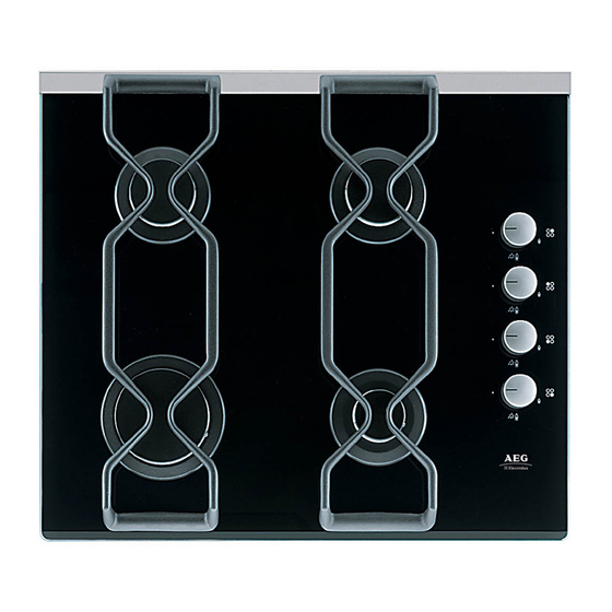
Description of the Hob 1. Hob Top 2. Rapid Burner 3. Semi-rapid Burners 4. Auxiliary Burner 5. Control knob for back right burner (semi-rapid) 6. Control knob for back left burner (semi-rapid) 7. Control knob for front left burner (rapid) 8. -
Page 6: Operation
Operation HOB BURNERS To light a burner, turn the relevant control knob anticlockwise to the maximum position, then push it down to ignite the burner. Upon, ignition, keep the knob pushed down about 5 seconds, then adjust the flame as required. If the burner does not ignite, turn the control knob to zero, and try again. -
Page 7: Maintenance And Cleaning
Maintenance and Cleaning Before any maintenance or cleaning can be carried out, you must DISCONNECT the hob from the electricity supply. The hob is best cleaned whilst it is still warm, as spillage can be removed more easily than if it is left to cool. Pan Supports To keep the pan supports in the correct position, they are mounted on metal pins... -
Page 8: Troubleshooting
Something Not Working? If the hob is not working correctly, please carry out the following checks before contacting your local AEG Service Force Centre. SYMPTOM There is no spark when lighting the The gas ring burns unevenly SOLUTION Check that the unit is plugged in and the electrical supply is switched on Check that the RCCB has not tripped (if fitted) -
Page 9: Service And Spare Parts
Service and Spare Parts If you require spare parts or an engineer contact your local Service Force Centre by telephoning: Your call will be routed to your local Service Force Centre. For the address of your local Service Force Centre and further information about Service Force, please visit the website at www.serviceforce.co.uk When you contact the Service Centre, they will need the following information: 1. -
Page 10: Guarantee Conditions
Guarantee Conditions Standard guarantee conditions We, AEG, undertake that if within 12 months of the date of the purchase this AEG appliance or any part thereof is proved to be defective by reason only of faulty workmanship or materials, we will, at our discretion repair or replace the same FREE OF CHARGE for labour, materials or carriage on condition that: •... -
Page 11: Instructions For The Installer
Instructions for the Installer Engineer technical data OVERALL DIMENSIONS Width: 580 mm. CUT OUT DIMENSIONS SUPPLY CONNECTIONS Gas: IGNITION HT SPARK HEAT INPUT Rear Left Burner 1.9 kW (6483 BTU/HR) (semi rapid) Front Left Burner 2.9 kW Natural Gas (9895 BTU/HR) (rapid) 2.7 kW L.P.G. -
Page 12: Important Safety Requirements
Instructions for the Installer TYPE OF GAS NOMINAL THERMAL POWER NATURAL GAS 20 mbar NOMINAL FLOW VALUE = RATE 37.78 MJ/m NOZZLE REFERENCE Ws - 50.7 MJ/ m 1/100 mm NOMINAL THERMAL LPG GAS POWER 28-30/37 mbar NOMINAL FLOW VALUE = RATE 49.92 MJ/Kg NOZZLE REFERENCE... -
Page 13: Location
Location The hob may be located in a kitchen, a kitchen/diner or bed sitting room, but not in a bathroom or shower room. Before making the cut out in the worktop ensure that there is a minimum distance of 55 mm. between the rear edge of the hob and the wall. A minimum distance of 100 mm. -
Page 14: Gas Connection
Instructions for the Installer FO 0264 A) End of shaft with nut B) Washer C) Elbow On the end of the shaft, which includes the GJ 1/2" threaded elbow, adjustment is fixed so that the washer is fitted between the components as shown in the diagram. Screw the parts together without using excessive force. -
Page 15: Cut Out Size
Cut Out Size The dimensions of the cut-out are given in the diagram. Building In Building over a cupboard or drawer If the hob is to be installed above a cupboard or drawer it will be necessary to fit a heat resistant board below the base of the hob on the underside of the work surface. -
Page 16: Building Over A Kitchen Unit With Door
Instructions for the Installer Building over a kitchen unit with door Proper arrangements must be taken in designing the furniture unit, in order to avoid any contact with the bottom of the hob which can be heated when it is operated. -
Page 17: Electrical Connections
Electrical connections Any electrical work required to install this hob should be carried out by a qualified electrician or competent person, in accordance with the current regulations. THIS HOB MUST BE EARTHED. The manufacturer declines any liability should these safety measures not be observed. This hob is designed to be connected to a 230-240V 50Hz AC electrical supply. -
Page 18: Permanent Connection
Instructions for the Installer Permanent Connection In the case of a permanent connection, it is necessary that you install a double pole switch between the hob and the electricity supply (mains), with a minimum gap of 3 mm. between the switch contacts and of a type suitable for the required load in compliance with the current electric regulations. -
Page 19: Fault Finding
Fault Finding Preliminary Electrical Systems Check START Isolate appliance and carry out: A: Earth Continuity check. Has inlet fuse blown? Inlet wiring faulty. Rectify any fault. Isolate appliance and carry out: B: Insulation check. Rectify any fault including replacing fuses as necessary. Carry out: Carry out: D: Resistance to... - Page 20 Instructions for the Installer A. EARTH CONTINUITY CHECK Appliance must be electrically disconnected - meter set on Ω (Ohms) x 1 scale and adjust zero if necessary. — Test leads from any appliance earth point to earth pin on plug. Resistance should be less than 0.1 Ω...
-
Page 21: Ignition System / Gas Ignition
Ignition System / Gas Ignition Ignitor does not spark Check plug top fuse and replace if necessary Check polarity and earth continuity of supply point Check earth continuity of appliance Check continuity from 'N' on the mains connector block and "O" on the ignitor unit Check continuity from 'L' on the mains connector block and the... -
Page 22: Commissioning
Instructions for the Installer Commissioning When the hob has been fully installed it will be necessary to check the minimum flame setting. To do this, follow the procedure below. 1) Turn the gas tap to the MAX position and ignite. 2) Set the gas tap to the MIN flame position then turn the control knob from MIN to MAX several times. -
Page 23: Conversion From Natural Gas To Lpg
Conversion from Natural Gas to LPG It is important to note that this model is designed for use with natural gas but can be converted for use with butane or propane gas providing the correct injectors are fitted and the gas rate is adjusted to suit. Method 1) Ensure that the gas taps are in the 'OFF' position 2) Isolate the hob from the electricity supply... - Page 24 © Electrolux plc 2003 From the Electrolux Group. The world’s No.1 choice. The Electrolux Group is the world’s largest producer of powered appliances for kitchen, cleaning and outdoor use. More than 55 million Electrolux Group products (such as refrigerators, cookers, washing machines, vacuum cleaners, chain saws and lawn mowers) are sold each year to a value of approx.
Need help?
Do you have a question about the GAS HOB 69802 G and is the answer not in the manual?
Questions and answers