Table of Contents
Advertisement
Quick Links
Advertisement
Table of Contents

Related Manuals for Asus TX97-L


Summary of Contents for Asus TX97-L
- Page 1 TX97-L Pentium Motherboard ® USER’S MANUAL...
- Page 2 Product warranty or service will not be extended if: (1) the product is repaired, modified or altered, unless such repair, modification of alteration is authorized in writing by ASUS; or (2) the serial number of the product is defaced or missing.
-
Page 3: Asus Contact Information
Technical Support BBS: +1-408-474-0569 Email: tsd-usa@asus.com.tw WWW: www.asus.com ASUS COMPUTER GmbH Marketing Info Address: Harkort Str. 25, 40880 Ratingen, BRD, Germany Telephone: 49-2102-445011 Fax: 49-2102-442066 Email: info-ger@asus.com.tw Technical Support BBS: 49-2102-448690 Email: tsd-ger@asus.com.tw Hotline: 49-2102-499712 ASUS TX97-L User’s Manual... -
Page 4: Table Of Contents
How this manual is organized ............7 Item Checklist .................. 7 II. FEATURES ..................8 Features of the ASUS TX97-L Motherboard ........8 Introduction to ASUS Smart Series of motherboards ... 9 Parts of the ASUS TX97-L Motherboard ........11 III. - Page 5 ASUS PCI-SC200 & PCI-SC860 SCSI Cards ........ 59 Setting Up the ASUS PCI-SC200 & PCI-SC860 ....... 60 Setting the INT Assignment for the ASUS PCI-SC200 ..... 60 Terminator Requirements for SCSI Devices ......60 Terminator Settings for the ASUS PCI-SC860 ......61 Terminator Settings for the ASUS PCI-SC200 ......
-
Page 6: Federal Communications Commission Statement
Canadian Department of Communications Statement This digital apparatus does not exceed the Class B limits for radio noise emissions from digital apparatus set out in the Radio Interference Regulations of the Canadian Department of Communications. ASUS TX97-L User’s Manual... -
Page 7: Introduction
Support Software: Information on the included support software VI. ASUS SCSI Cards: Installation of ASUS SCSI cards (optional) VII. ASUS L101 Card: Installation of the ASUS LAN card (optional) Item Checklist Please check that your package is complete. If you discover damaged or missing items, please contact your retailer. -
Page 8: Features
II. FEATURES Features of the ASUS TX97-L Motherboard The ASUS TX97-L is carefully designed for the demanding PC user who wants many intelligent features in a small package. This motherboard: • Intel Chipset: Features Intel’s 430TX PCIset with I/O subsystems. -
Page 9: Introduction To Asus Smart Series Of Motherboards
OS such as in the next release of Windows 95 must be used. • PC ’97 Compliant - Both the BIOS and hardware levels of ASUS TX97 series of motherboards meet PC ’97 compliancy. The new PC 97 requirements for... - Page 10 Message LED - Chassis LEDs now act as information providers. Through the way a particular LED illuminates, the user can determine the stage the computer is in. A simple glimpse provides useful information to the user. ASUS TX97-L User’s Manual...
-
Page 11: Parts Of The Asus Tx97-L Motherboard
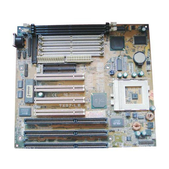
II. FEATURES Parts of the ASUS TX97-L Motherboard Programmable PS/2 Mouse, USB, IrDA Super Multi-I/O Flash ROM Serial, Parallel, Floppy Hardware Monitor Thermal Sensor 3 ISA Slots 4 PCI Slots IDE Connectors AT Power Connector ATX Power 3 DIMM Sockets Intel’s 430TX... -
Page 12: Installation
III. INSTALLATION ASUS TX97-L Motherboard Layout Key- PS/2 Mouse, COM 1 Hardware Boot Block USB, IrDA Monitor board Serial Ports Write Keyboard COM 2 Power LM78 Thermal Sensor System BIOS Parallel (Printer) Port Flash EEPROM Wake on LAN Power Fan... - Page 13 31 Speaker Output Connector (4 pins) 20) W0LCON p. 32 Wake on LAN Activity Connector (3-pins) The onboard hardware monitor uses the address 290H-297H so legacy ISA cards must not use this address or else conflicts will occur. ASUS TX97-L User’s Manual...
-
Page 14: Installation Steps
3. Hold components by the edges and try not to touch the IC chips, leads or connectors, or other components. 4. Place components on a grounded antistatic pad or on the bag that came with the component whenever the components are separated from the system. ASUS TX97-L User’s Manual... -
Page 15: Jumper Settings
(4) Hold down <Delete> during bootup and enter BIOS setup to re- enter user preferences. RTC RAM CLRTC Clear Data [short solder pointS (Position R73) momentarily] CLRTC Short solder points to Clear Data Thermal Sensor RTC RAM (Clear Data) ASUS TX97-L User’s Manual... - Page 16 External frequency (called the BUS Clock) within the CPU. These must be set together with the above jumpers CPU External (BUS) Frequency Selection. WARNING! Frequencies above 66MHz exceed the specifications for the onboard Intel Chipset and are not guaranteed to be stable. ASUS TX97-L User’s Manual...
- Page 17 66MHz [1-2] [2-3] [2-3] [----] [2-3] [1-2] AMD-K6-PR166 166MHz E-2.5x 66MHz [1-2] [2-3] [2-3] [----] [2-3] [2-3] *NOTE: The only IBM or Cyrix 6x86(L) (or M1) that is supported on this motherboard is revision 2.7 or later. (see next page). ASUS TX97-L User’s Manual...
-
Page 18: Compatible Cyrix Cpu Identification
AMD (.25micron) K6-233,266,300 ---- 2.2V(Dual) [----] [1-2] [----] 2.0Volts 2.1Volts 2.2Volts 2.3Volts 2.4Volts 3.4V (STD) 2.5Volts 2.6Volts 2.7Volts 2.8Volts 2.9Volts 3.5V (VRE) Thermal Sensor 3.0Volts 3.1Volts 3.2Volts 3.3Volts Single Plane Dual Plane CPU CPU Vcore Voltage Selection ASUS TX97-L User’s Manual... -
Page 19: System Memory (Dimm)
Socket 3 will not support 64, 128, or 256MB DIMMs with 64Mbit SDRAM cells. • If Socket 1 and/or Socket 2 has 64, 128, or 256MB DIMM’s with 64Mbit SDRAM cells, Socket 3 must be empty. ASUS TX97-L User’s Manual... - Page 20 III. INSTALLATION (This page was intentionally left blank) ASUS TX97-L User’s Manual...
-
Page 21: Dimm Memory Installation
DIMM to be inserted into the DIMM socket on the motherboard. Four clock signals are supported on this motherboard. You must ask your retailer for the specifications before purchasing memory modules. ASUS TX97-L User’s Manual... -
Page 22: Central Processing Unit (Cpu)
IMPORTANT: You must set jumpers for “CPU to BUS Frequency Ratio” and jumpers for “BUS Frequency Selection” depending on the CPU that you install. Lever Lock Blank Thermal Sensor Notch ZIF Socket 7 with Pentium Processor ASUS TX97-L User’s Manual... -
Page 23: Expansion Cards
Both ISA and PCI expansion cards may need to use IRQs. System IRQs are avail- able to cards installed in the ISA expansion bus first, and any remaining IRQs are then used by PCI cards. Currently, there are two types of ISA cards. ASUS TX97-L User’s Manual... -
Page 24: Assigning Dma Channels For Isa Cards
Used By ISA and DMA x Used By ISA for those IRQs and DMAs you want to reserve). ISA Cards and Hardware Monitor The onboard hardware monitor uses the address 290H-297H so legacy ISA cards must not use this address or else conflicts will occur. ASUS TX97-L User’s Manual... -
Page 25: External Connectors
WARNING! Some pins are used for connectors or power sources. These are clearly separated from jumpers in “Map of the ASUS Motherboard.” Placing jumper caps over these will cause damage to your motherboard. IMPORTANT: Ribbon cables should always be connected with the red stripe on the Pin 1 side of the connector. - Page 26 (using the 25-Pin male) to a free expansion Pin 1 slot opening. COM 2 TIP: You may also remove the bracket connectors and mount them directly to the Pin 1 case to save expansion slot space. Thermal Sensor Serial Port Connectors ASUS TX97-L User’s Manual...
- Page 27 This lead is for an open chassis monitor. A high level signal to the CHASSIS lead will indicate to the system that the chassis has been opened. +5Volt (Power Supply Stand By) Chassis Signal Ground Thermal Sensor Chassis open alarm lead ASUS TX97-L User’s Manual...
- Page 28 Primary or Secondary IDE connectors will cause the LED to light up. TIP: If the case-mounted LED does not light, try reversing the 2-Pin plug. IDE LED Thermal Sensor IDE (Hard Drive) LED Lead ASUS TX97-L User’s Manual...
- Page 29 Power Supply AT Power Connector Using a slight angle, align the plastic guide pins on the lead to their receptacles on the connector. Once aligned, press the lead onto the connector until the lead locks into place. ASUS TX97-L User’s Manual...
- Page 30 Front View Back View (NC) IRRX IRTX IRTX (NC) IRRX For the infrared feature to be available, Thermal Sensor you must connect an optional Infrared module to the motherboard. Infrared Module Connector ASUS TX97-L User’s Manual...
- Page 31 Power LED & LOCK Keyboard Lock SMI Lead ATX Power Speaker Switch* Connector Reset SW SPKR Requires an ATX power supply, optional ATX to Thermal Sensor AT power connector adapter, and a momentary switch button. System Panel Connectors ASUS TX97-L User’s Manual...
- Page 32 The WAKE_LAN connector allows the system to power up when there is a wakeup package (signal) received from the network through the ASUS PCI- L101 LAN card. Requires the ASUS PCI-L101 and an ATX power supply with at least 720mAmp 5VSB.
-
Page 33: Power Connection Procedures
Shut down the computer?. The system will give three quick beeps after about 30 seconds and then power off after Windows shuts down. NOTE: The message “You can now safely turn off your computer” will not appear when shutting down with ATX power supplies. ASUS TX97-L User’s Manual... -
Page 34: Bios Software
“Save Current BIOS To File” option. If the boot block in the file is different from the current boot block, this option will not update the main block. Instead, it will display the following messages. ASUS TX97-L User’s Manual... -
Page 35: Advanced Features Menu
This option erases the Plug-and-Play (PnP) configuration record. 2. Update BIOS Including Boot Block and ESCD This option updates the boot block, the baseboard BIOS, and the PnP extended sys- tem configuration data (ESCD) parameter block from a new BIOS file. ASUS TX97-L User’s Manual... -
Page 36: Managing & Updating Your Motherboard's Bios
PnP BIOS and therefore cannot be programmed by the Flash Memory Writer utility. 1. Download an updated ASUS BIOS file from the internet (WWW), FTP, or a BBS (Bulletin Board Service) and save to the diskette you created above. See ASUS CONTACT INFORMATION on Page II of the User’s Manual for details. -
Page 37: Bios Setup
Reset button on the system case. You can also restart by turning the system off and then back on again. But do so only if the first two methods fail. When you invoke Setup, the CMOS SETUP UTILITY main program screen will appear with the following options: ASUS TX97-L User’s Manual... -
Page 38: Load Defaults
To set the date, highlight the “Date” field and then press either <Page Up>/<Page Down> or <+>/<–> to set the current date. Follow the month, day and year format. Valid values for month, day and year are: Month: (1 to 12), Day: (1 to 31), Year: (up to 2079) ASUS TX97-L User’s Manual... - Page 39 IDE hard disks; set it to Large for drives over 528MB that do not sup- port LBA. Large type of drive can only be used with MS-DOS and is very uncom- mon. Most IDE drives over 528MB support the LBA mode. ASUS TX97-L User’s Manual...
- Page 40 If you are using a VGA or any higher resolution card, choose EGA/VGA. Halt On (All Errors) This field determines which types of errors will cause the system to halt. Choose from All Errors; No Errors; All,But Keyboard, All,But Diskette; and All,But Disk/Key. ASUS TX97-L User’s Manual...
-
Page 41: Bios Features Setup
This field speeds up the Power-On Self Test (POST) routine by skipping retesting a second, third, and forth time. Setup default setting for this field is Enabled. A com- plete test of the system is done on each test. ASUS TX97-L User’s Manual... - Page 42 Enable this option otherwise leave this on the setup default of Disabled............................Video ROM BIOS Shadow (Enabled) This field allows you to change the video BIOS location from ROM to RAM. Relocat- ing to RAM enhances system performance, as information access is faster than the ROM. ASUS TX97-L User’s Manual...
-
Page 43: Chipset Features Setup
The default setting of 60ns DRAM sets the optimal timings for items 2 through 9 for 60ns DRAM modules. If you are using 70ns DRAM modules, you must change this item to 70ns DRAM. See section III for DRAM installation information. ASUS TX97-L User’s Manual... - Page 44 IV. BIOS SOFTWARE SDRAM CAS# Latency (3T) If you use ASUS SDRAM DIMM modules, you can set this to 2T for better perfor- mance, otherwise leave on default or check with your vendor for DIMM specs. SDRAM Speculative Read (Disabled) If Enabled, the CPU will issue predict commands to access the DRAM, if a miss occurs, the CPU will cancel this command.
- Page 45 Because each IDE device may have a different Mode timing (0, 1, 2, 3, 4), it is necessary for these to be independent. PIO and DMA timings can be independently set. The default setting of Auto will allow autodetection to ensure optimal performance. ASUS TX97-L User’s Manual...
-
Page 46: Power Management Setup
Video Off Option (Susp,Stby -> Off ) This field determines when to activate the video off feature for monitor power management. The settings are All Modes -> Off; Always On; Suspend -> Off; and Susp,Stby -> Off . ASUS TX97-L User’s Manual... - Page 47 Turning an external modem off and then back on while the computer is off causes an initializa- tion string that will also cause the system to power on. ASUS TX97-L User’s Manual...
-
Page 48: Pnp And Pci Setup
You will then be prompted to “Press F1 to continue, DEL to enter SETUP”. PNP and PCI Setup This “PNP and PCI Setup” option configures the PCI bus slots. All PCI bus slots on the system use INTA#, thus all installed PCI cards must be set to this value. ASUS TX97-L User’s Manual... -
Page 49: Details Of Pnp And Pci Setup
ISA MEM Block BASE to its default setting of No/ICU. SYMBIOS SCSI BIOS (Auto) The default uses Auto settings for the onboard SCSI BIOS. If you do not want to use the onboard SCSI BIOS, choose Disabled. ASUS TX97-L User’s Manual... -
Page 50: Load Bios Defaults
<Enter>. The system displays a confirmation message on the screen. Press <Y> and then <Enter> to confirm. Press <N> and then <Enter> to abort. This feature does not affect the fields on the Standard CMOS Setup screen. ASUS TX97-L User’s Manual... -
Page 51: Supervisor Password And User Password
<Enter> instead of entering a new password when the “Enter Password” prompt appears. A message confirms the password has been disabled. NOTE: If you forget the password, see CMOS RAM in section III for procedures on clearing the CMOS. ASUS TX97-L User’s Manual... -
Page 52: Ide Hdd Auto Detection
The auto-detection feature can only detect one set of parameters for a particular IDE hard drive. Some IDE drives can use more than one set. This is not a problem if the drive is new and empty. ASUS TX97-L User’s Manual... -
Page 53: Save & Exit Setup
Select this option to exit the Setup utility without saving the modifications you specify during the current session. To exit without saving, highlight the “Exit Without Sav- ing” option on the main screen and then press <Enter>. ASUS TX97-L User’s Manual... - Page 54 (This page was intentionally left blank) ASUS TX97-L User’s Manual...
-
Page 55: Asus Smart Motherboard Support Cd 3.10
Patch for PIIX4 chipset: Installs the necessary drivers for PCI card and PCI bridge for Windows 95/95a (OSR1) and 95b (OSR2) for ASUS motherboards. • Browse this CD: Allows you to see the contents of the ASUS support CD. • Technical Support Form: View the Technical Support Form with Notepad. -
Page 56: Desktop Management Interface (Dmi)
V. SUPPORT SOFTWARE Desktop Management Interface (DMI) Introducing the ASUS DMI Configuration Utility This motherboard supports DMI within the BIOS level and provides a DMI Con- figuration Utility to maintain the Management Information Format Database (MIFD). DMI is able to auto-detect and record information pertinent to a computer’s system such as the CPU type, CPU speed, and internal/external frequencies, and memory size. -
Page 57: Using The Asus Dmi Configuration Utility
V. SUPPORT SOFTWARE Using the ASUS DMI Configuration Utility Edit DMI (or delete) Use the (left-right) cursors to move the top menu items and the (up-down) cursor to move between the left hand menu items. The bottom of the screen will show the available keys for each screen. - Page 58 You can load the BIOS defaults from a MIFD file and can clear all user modified and added data. You must reboot your computer in order for the defaults to be saved back into the Flash BIOS. ASUS TX97-L User’s Manual...
-
Page 59: Asus Pci Scsi Cards
SCO UNIX floppy disk. Windows 95 support is also available using the device drivers included within the Windows software. The ASUS PCI-SC200 and ASUS PCI-SC860 are Plug and Play adapters that are auto detected by BIOS and current operating systems that support Plug and Play features. -
Page 60: Setting Up The Asus Pci-Sc200 & Pci-Sc860
VI. ASUS PCI SCSI Cards Setting Up the ASUS PCI-SC200 & PCI-SC860 There are two jumper settings you may need to make on the ASUS PCI-SC200 to set it up. One setting assigns the PCI INT interrupt, the other sets the card’s termination. -
Page 61: Terminator Settings For The Asus Pci-Sc860
Not Terminated Terminator Setting (Terminated / Not Terminated) Decide whether or not you need to terminate the ASUS PCI-SC200 based on its position in the SCSI chain. Only the devices at each end of the chain need to be terminated. If you have only internal or only external devices connected to the ASUS PCI-SC200, then you must terminate the ASUS PCI-SC200. -
Page 62: Scsi Id Numbers For Scsi Devices
SCSI identification number that is not in use by any other SCSI device. There are eight possible ID numbers, 0 through 7. The ASUS PCI-SC200 and ASUS PCI-SC860 cards have fixed SCSI IDs of 7. The SCSI ID serves two purposes: •... -
Page 63: Asus Lan Card
Motherboard type Other If you are using the ASUS PCI-L101 on an ASUS motherboard, leave the jumper on its defaut setting of “ASUS.” If you are using another brand of motherboard, set the jumper to “Other.” Connect the Wake on LAN (WOL) output signal to the motherboard’s WOL_CON in order to utilize the wake on LAN feature of the moth-... -
Page 64: Features
A: To enable Wake-On-LAN function, your system requires Ethernet LAN adapter card that can activate Wake-On-LAN function, a client with Wake-On-LAN capa- bility, and software such as LDCM Rev. 3.10 or up that can trigger wake-up frame. ASUS TX97-L User’s Manual...
Need help?
Do you have a question about the TX97-L and is the answer not in the manual?
Questions and answers