Intel D845GLVA Product Manual
Desktop board
Hide thumbs
Also See for D845GLVA:
- Specification (114 pages) ,
- Specification (15 pages) ,
- Quick reference (18 pages)
Table of Contents
Advertisement
Advertisement
Table of Contents

Subscribe to Our Youtube Channel
Related Manuals for Intel D845GLVA

Summary of Contents for Intel D845GLVA
- Page 1 Intel Desktop Board ® D845GLVA Product Guide Order Number: C30686-001...
-
Page 2: Revision History
Intel may make changes to specifications and product descriptions at any time, without notice. Desktop Board D845GLVA may contain design defects or errors known as errata which may cause the product to deviate from published specifications. Current characterized errata are available on request. -
Page 3: Table Of Contents
Contents 1 Desktop Board Features Desktop Board Components ....................9 Processor ........................... 10 Main Memory ........................11 ® Intel 845GL Chipset......................11 ® Intel 82845GL Graphics and Memory Controller Hub (GMCH) ........ 11 ® Intel 82801DB I/O Controller Hub (ICH4)..............12 Firmware Hub (FWH).................... - Page 4 Intel Desktop Board D845GLVA Product Guide Installing and Removing Memory ..................23 Installing DIMMs ......................24 Removing DIMMs ...................... 24 Connecting the IDE Cable ....................25 Connecting the Front Panel Header ................... 26 Installing a USB 2.0 Solution ....................26 Installing a Front Panel Audio Solution ................
- Page 5 Contents Add-In Card and Peripheral Interface Connectors..........59 Internal Headers ......................60 Desktop Board Resources....................62 Memory Map ......................62 DMA Channels ......................62 Interrupts ........................63 A Error Messages and Indicators BIOS Beep Codes ......................65 BIOS Error Messages ......................66 B Regulatory Compliance Safety Regulations ......................
- Page 6 Intel Desktop Board D845GLVA Product Guide Tables 1. Feature Summary ......................7 2. Processors Supported by the Desktop Board .............. 10 3. RJ-45 LAN Connector LEDs ..................13 4. Jumper Settings for the BIOS Setup Program Modes (J9H2) ........27 5.
-
Page 7: Desktop Board Features
Desktop Board D845GLVA has been designed to support DIMMs based on 512 Mbit NOTE: technology up to 2 GB, but this technology has not been validated on this Intel desktop board. For more information about the latest list of tested memory, refer to the Intel World Wide Web site at: http://support.intel.com/support/motherboards/desktop/... - Page 8 Management • Support for Suspend to RAM (Instantly Available PC) ✏ NOTE For information about this Intel desktop board, including the Technical Product Specification (TPS), BIOS updates, and device drivers, go to the Intel World Wide Web site at: http://support.intel.com/support/motherboards/desktop/...
-
Page 9: Desktop Board Components
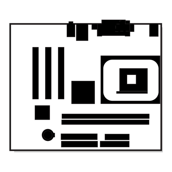
Desktop Board Features Desktop Board Components Figure 1 shows the location of the major components on Desktop Board D845GLVA. OM15859 Front panel audio header Primary IDE connector CD-ROM connector (ATAPI) Speaker Back panel connectors Battery 12 V processor core voltage connector... -
Page 10: Processor
CAUTION Failure to use an ATX12V or SFX-12V power supply, or not connecting the additional power supply lead to Desktop Board D845GLVA may result in damage to the desktop board and/or power supply. Desktop Board D845GLVA supports a single Intel Pentium 4 processor or Intel Celeron processor. -
Page 11: Main Memory
✏ NOTE Desktop Board D845GLVA has been designed to support DIMMs based on 512 Mbit technology up to 2 GB, but this technology has not been validated on this board. For more information about the latest list of tested memory, refer to the Intel World Wide Web site at: http://support.intel.com/support/motherboards/desktop/... -
Page 12: Intel ® 82801Db I/O Controller Hub (Ich4)
• AC ’97 2.1 compliant link for audio and telephony codecs • Integrated Intel 82562ET 10/100 Mbit/sec Platform LAN Connect (PLC) device for interfacing the ICH4 LAN connect interface to LAN connect component • Three UHCI and one ECHI compliant host controllers supporting up to four USB ports... -
Page 13: Audio Subsystem
• Configurable EEPROM that contains the MAC address LAN Subsystem Software For LAN software and drivers, refer to the D845GLVA link on Intel’s World Wide Web site at: http://support.intel.com/support/motherboards/desktop/ RJ-45 LAN Connector LEDs Two LEDs are built into the RJ-45 LAN connector. Table 3 describes the LED states when the desktop board is powered up and the LAN subsystem is operating. -
Page 14: Hi-Speed Usb 2.0 Support
• Laser servo (LS-120) drives Expansion Slots Desktop Board D845GLVA has three PCI bus add-in card connectors. BIOS The BIOS provides the Power-On Self-Test (POST), the BIOS Setup program, the PCI and IDE auto-configuration utilities, and the video BIOS. The BIOS is stored in the Firmware Hub. -
Page 15: Pci Auto Configuration
Desktop Board Features PCI Auto Configuration If you install a PCI add-in card in your computer, the PCI auto-configuration utility in the BIOS automatically detects and configures the resources (IRQs, DMA channels, and I/O space) for that add-in card. You do not need to run the BIOS Setup program after you install a PCI add-in card. IDE Auto Configuration If you install an IDE device (such as a hard drive) in your computer, the IDE auto-configuration utility in the BIOS automatically detects and configures the device for your computer. -
Page 16: Suspend To Ram (Instantly Available Pc Technology)
Intel Desktop Board D845GLVA Product Guide Suspend to RAM (Instantly Available PC Technology) CAUTION For Instantly Available PC technology, the 5 V standby line for the power supply must be capable of delivering adequate +5 V standby current. Failure to provide adequate standby current when using this feature can damage the power supply and/or effect ACPI S3 sleep state functionality. -
Page 17: Hardware Management
• PME# wake up support Power Connectors Desktop Board D845GLVA has two power connectors. See Figure 13 on page 58 for the location of the power connectors. Fan Connectors Desktop Board D845GLVA has two chassis fan connectors and one processor fan connector. See Figure 13 on page 58 for the location of the fan connectors. -
Page 18: Battery
Intel Desktop Board D845GLVA Product Guide Battery A battery on the board keeps the values in CMOS RAM and the clock current when the computer is turned off. See Chapter 2 starting on page 19 for instructions on how to replace the battery. -
Page 19: Installing And Replacing Desktop Board Components
2 Installing and Replacing Desktop Board Components This chapter tells you how to: • Install the I/O shield • Install and remove the desktop board • Install and remove a processor • Install and remove memory • Connect the IDE cable •... -
Page 20: Installing The I/O Shield
Intel Desktop Board D845GLVA Product Guide Installing the I/O Shield The desktop board comes with an I/O shield. When installed in the chassis, the shield blocks radio frequency transmissions, protects internal components from dust and foreign objects, and promotes correct airflow within the chassis. -
Page 21: Installing And Removing The Desktop Board
You will need a Phillips* (#2 bit) screwdriver. Refer to Appendix B for regulatory requirements and installation instructions and precautions. Figure 4 shows the location of the six mounting holes for Desktop Board D845GLVA. OM15861 Figure 4. Desktop Board Mounting Screw Holes... -
Page 22: Installing And Removing A Processor
Installing the Processor Fan Heatsink The desktop board has an integrated processor fan heatsink retention mechanism (RM). For instructions on how to install the processor fan heatsink to the integrated processor fan heatsink RM, refer to the Intel World Wide Web site at: http://support.intel.com/support/processors/pentium4/intnotes478.htm... -
Page 23: Connecting The Processor Fan Heatsink Cable
OM15862 Figure 6. Connecting the Processor Fan Heatsink Cable to the Processor Fan Header Removing a Processor For instruction on how to remove the processor fan heatsink, refer to the Intel World Wide Web site at: http://support.intel.com/support/processors/pentium4/intnotes478.htm Installing and Removing Memory... -
Page 24: Installing Dimms
Intel Desktop Board D845GLVA Product Guide Installing DIMMs To install DIMMs, follow these steps: 1. Observe the precautions in “Before You Begin” on page 19. 2. Turn off all peripheral devices connected to the computer. Turn off the computer and disconnect the AC power cord. -
Page 25: Connecting The Ide Cable
Installing and Replacing Desktop Board Components Connecting the IDE Cable ® The Intel boxed desktop board package includes an IDE cable. The cable connects two drives to the desktop board. The cable supports both ATA-66 and ATA-100 transfer protocols and is backward compatible with drives using slower IDE transfer protocols. -
Page 26: Connecting The Front Panel Header
Intel Desktop Board D845GLVA Product Guide Connecting the Front Panel Header Before connecting the front panel header, observe the precautions in “Before You Begin” on page 19. Refer to Table 31 on page 61 for pin assignments. Installing a USB 2.0 Solution Before installing a USB 2.0 solution, observe the precautions in “Before You Begin”... -
Page 27: Setting The Bios Configuration Jumper Block
Installing and Replacing Desktop Board Components Setting the BIOS Configuration Jumper Block Figure 9 shows the location of the BIOS configuration jumper block. J9H2 OM15857 Figure 9. Location of the BIOS Configuration Jumper Block The three-pin BIOS jumper block enables all board configurations to be done in BIOS Setup. Table 4 shows the jumper settings for the Setup program modes. -
Page 28: Clearing Passwords
Intel Desktop Board D845GLVA Product Guide Clearing Passwords This procedure assumes that the board is installed in the computer and the configuration jumper block is set to normal mode. 1. Observe the precautions in “Before You Begin” on page 19. - Page 29 Installing and Replacing Desktop Board Components FORHOLDSREGEL Eksplosionsfare, hvis batteriet erstattes med et batteri af en forkert type. Batterier bør om muligt genbruges. Bortskaffelse af brugte batterier bør foregå i overensstemmelse med gældende miljølovgivning. (Danish) OBS! Det kan oppstå eksplosjonsfare hvis batteriet skiftes ut med feil type. Brukte batterier bør kastes i henhold til gjeldende miljølovgivning.
-
Page 30: Removing The Battery From The Desktop Board
Intel Desktop Board D845GLVA Product Guide ATENÇÃO Haverá risco de explosão se a bateria for substituída por um tipo de bateria incorreto. As baterias devem ser recicladas nos locais apropriados. A eliminação de baterias usadas deve ser feita de acordo com as regulamentações ambientais da região. -
Page 31: Updating The Bios With The Intel ® Express Bios Update Utility
3 Updating the BIOS This chapter tells you how to update the BIOS by either using the Intel Express BIOS Update ® utility or the Intel Flash Memory Update Utility, and how to recover the BIOS if an update fails. -
Page 32: Updating The Bios
Intel Iflash BIOS Update utility file. ✏ NOTE Review the instructions distributed with the update utility before attempting a BIOS update. The Intel Iflash BIOS update utility allows you to: • Update the BIOS in flash memory • Update the language section of the BIOS... - Page 33 Updating the BIOS 6. Listen to the speaker: • Upon applying power, drive A will begin to show activity. In about a minute, two beeps are heard and drive A activity ceases (temporarily) indicating the successful recovery of the BIOS core. Drive A activity will begin again followed by two more beeps indicating the successful recovery of the boot block.
- Page 34 Intel Desktop Board D845GLVA Product Guide...
-
Page 35: Using The Bios Setup Program
✏ NOTE The BIOS Setup menus described in this section may not show the latest settings. For the latest BIOS settings, refer to the Intel Desktop Board D845GLVA Technical Product Specification or the Intel World Wide Web site at: http://support.intel.com/support/motherboards/desktop/ ✏... -
Page 36: Maintenance Menu
Clears the Wired for Management Boot Integrity Service (BIS) credentials. • Cancel CPU Stepping Signature No options Displays processor’s Stepping Signature. CPU Microcode Update No options Displays processor’s Microcode Update Revision. Revision * For information about the BIS, refer to the Intel Web site at: http://developer.intel.com/design/security/index1.htm... -
Page 37: Main Menu
Using the BIOS Setup Program Main Menu Maintenance Main Advanced Security Power Boot Exit Table 8 describes the Main Menu. This menu reports processor and memory information and is used to configure the system date and system time. Table 8. Main Menu Feature Options... -
Page 38: Advanced Menu
Intel Desktop Board D845GLVA Product Guide Advanced Menu Maintenance Main Advanced Security Power Boot Exit PCI Configuration Boot Configuration Peripheral Configuration IDE Configuration Diskette Configuration Event Log Configuration Video Configuration USB Configuration Chipset Configuration Table 9 describes the Advanced Menu. This menu is used to set advanced features that are available through the chipset. -
Page 39: Pci Configuration Submenu
Using the BIOS Setup Program PCI Configuration Submenu Maintenance Main Advanced Security Power Boot Exit PCI Configuration The submenu shown in Table 10 is used to configure the IRQ priority of PCI slots individually. Table 10. PCI Configuration Submenu Feature Options Description •... -
Page 40: Boot Configuration Submenu
Intel Desktop Board D845GLVA Product Guide Boot Configuration Submenu Maintenance Main Advanced Security Power Boot Exit Boot Configuration The submenu shown in Table 11 is used to set the Plug & Play options and the power-on state of the Numlock key. -
Page 41: Peripheral Configuration Submenu
Using the BIOS Setup Program Peripheral Configuration Submenu Maintenance Main Advanced Security Power Boot Exit Peripheral Configuration This submenu shown in Table 12 is used for configuring computer peripherals. Table 12. Peripheral Configuration Submenu Feature Options Description • Disabled Serial Port A Configures serial port A. - Page 42 Intel Desktop Board D845GLVA Product Guide Table 12. Peripheral Configuration Submenu (continued) Feature Options Description • 378 (default) Base I/O Address Specifies the base I/O address for the parallel port, if (This feature is present Parallel Port is Enabled. • 278...
-
Page 43: Ide Configuration Submenu
Using the BIOS Setup Program IDE Configuration Submenu Maintenance Main Advanced Security Power Boot Exit IDE Configuration This submenu shown in Table 13 is used to configure IDE device options. Table 13. IDE Configuration Submenu Feature Options Description • Disabled IDE Controller Specifies the integrated IDE controller. -
Page 44: Primary/Secondary Ide Master/Slave Submenus
Intel Desktop Board D845GLVA Product Guide Primary/Secondary IDE Master/Slave Submenus Maintenance Main Advanced Security Power Boot Exit ➜ IDE Configuration Primary IDE Master Primary IDE Slave Secondary IDE Master Secondary IDE Slave There are four IDE submenus: Primary master, primary slave, secondary master, and secondary slave. -
Page 45: Diskette Configuration Submenu
Using the BIOS Setup Program Diskette Configuration Submenu Maintenance Main Advanced Security Power Boot Exit Diskette Configuration This submenu shown in Table 15 is used to configure the diskette drive. Table 15. Diskette Configuration Submenu Feature Options Description • Disabled Floppy Controller Configures the integrated diskette controller. -
Page 46: Event Log Configuration Submenu
Intel Desktop Board D845GLVA Product Guide Event Log Configuration Submenu Maintenance Main Advanced Security Power Boot Exit Event Log Configuration The submenu shown in Table 16 is used to configure the event logging features. Table 16. Event Log Configuration Submenu... -
Page 47: Video Configuration Submenu
Using the BIOS Setup Program Video Configuration Submenu Maintenance Main Advanced Security Power Boot Exit Video Configuration The submenu shown in Table 17 is used to configure video features. Table 17. Video Configuration Submenu Feature Options Description • 4 MB Graphics Aperture Size Amount of system memory available for direct access by •... -
Page 48: Chipset Configuration Submenu
Intel Desktop Board D845GLVA Product Guide Chipset Configuration Submenu Maintenance Main Advanced Security Power Boot Exit Chipset Configuration The menu shown in Table 19 is used to configure advanced chipset features. Table 19. Chipset Configuration Submenu Feature Options Description • Default (default) -
Page 49: Security Menu
Using the BIOS Setup Program Security Menu Maintenance Main Advanced Security Power Boot Exit The menu shown in Table 20 is used to set passwords and security features. Table 20. Security Menu If no password entered previously: Feature Options Description Supervisor Password Is No options Reports if there is a supervisor password set. -
Page 50: Power Menu
Intel Desktop Board D845GLVA Product Guide Power Menu Maintenance Main Advanced Security Power Boot Exit The menu shown in Table 21 is used to set power management features. Table 21. Power Menu Feature Options Description ACPI No Options When selected, displays the ACPI submenu. -
Page 51: Boot Menu
Silent Boot Disabled displays normal POST messages. • Enabled (default) Enabled displays OEM logo instead of POST messages. • Disabled Intel Rapid BIOS Boot Allows BIOS to skip certain tests while booting. • Enabled (default) • Disabled Scan User Flash Area Enables the BIOS to scan the flash ROM for user binary files that are executed at boot time. -
Page 52: Boot Device Priority Submenu
Intel Desktop Board D845GLVA Product Guide Boot Device Priority Submenu Maintenance Main Advanced Security Power Boot Exit Boot Device Priority The submenu represented in Table 24 is for setting boot devices priority. Table 24. Boot Device Priority Submenu Options Description Feature •... -
Page 53: Removable Devices Submenu
Using the BIOS Setup Program Removable Devices Submenu Maintenance Main Advanced Security Power Boot Exit Removable Devices The submenu in shown Table 26 is for setting removable devices. Table 26. Removable Devices Submenu Feature Options Description Removable Device Dependent on installed Specifies the boot sequence from the available (Note) removable devices... -
Page 54: Exit Menu
Intel Desktop Board D845GLVA Product Guide Exit Menu Maintenance Main Advanced Security Power Boot Exit The menu shown in Table 28 is used to exit the BIOS Setup program, saving changes, and loading and saving defaults. Table 28. Exit Menu... -
Page 55: Technical Reference
5 Technical Reference Board Connectors The board connectors can be divided into three groups: • Back panel connectors • Midboard connectors — Audio connectors — Fan headers and power connectors — Add-in board and peripheral interface connectors • Internal headers CAUTION Many of the midboard and front panel connectors provide operating voltage (+5 V dc and +12 V dc, for example) to devices inside the computer chassis, such as fans and internal... -
Page 56: Back Panel Connectors
Intel Desktop Board D845GLVA Product Guide Back Panel Connectors ✏ NOTE The line out connector, located on the back panel, is designed to power either headphones or amplified speakers only. Poor audio quality may occur if passive (non-amplified) speakers are connected to this output. -
Page 57: Midboard Connectors
Technical Reference Midboard Connectors Audio Figure 12 shows the location of the front panel audio header (A) and ATAPI-style CD-ROM connector (B). OM15865 Item Description Front panel audio CD-ROM (Atapi-style) Figure 12. Audio Connectors Table 29 shows the pin assignments for the front panel audio header. Table 29. -
Page 58: Fan Headers And Power Connectors
Failure to use an ATX12V or SFX-12V power supply, or not connecting the additional power supply lead to Desktop Board D845GLVA may result in damage to the desktop board. Desktop Board D845GLVA requires an ATX12V or SFX-12V compliant power supply to function according to desktop board specifications. -
Page 59: Add-In Card And Peripheral Interface Connectors
Technical Reference Add-In Card and Peripheral Interface Connectors Figure 14 shows the add-in card and peripheral interface connectors. OM15864 Item Description Item Description PCI bus connector 3 Floppy drive PCI bus connector 2 (SMBus routed) Primary IDE PCI bus connector 1 Secondary IDE Figure 14. -
Page 60: Internal Headers
Intel Desktop Board D845GLVA Product Guide Internal Headers Figure 15 shows the location of internal headers. J9F2 J9G1 J8H3 OM15869 Label Description USB 2.0 Power LED Front panel Figure 15. Internal Headers... -
Page 61: Usb 2.0 Header (J9F2)
Technical Reference Table 30 shows the pin assignments for the USB 2.0 header. Table 30. USB 2.0 Header (J9F2) Signal name Signal name VBUS0 (Power) VBUS1 (Power) Ground Ground Key (no pin) Not connected Note: USB ports may be assigned as needed. Table 31 shows the pin assignments for the front panel header. -
Page 62: Desktop Board Resources
Intel Desktop Board D845GLVA Product Guide Desktop Board Resources Memory Map Table 32. System Memory Map Address Range (decimal) Address Range (hex) Size Description 1024 K - 2097152 K 100000 - 7FFFFFFF 2047 MB Extended Memory 960 K - 1024 K... -
Page 63: Interrupts
Technical Reference Interrupts Table 34. Interrupts System Resource I/O channel check Reserved, interval timer Reserved, keyboard buffer full Reserved, cascade interrupt from slave PIC COM2* COM1* LPT2 (Plug & Play option) / ** Diskette drive controller LPT1* Real time clock Onboard mouse port (if present, else user available) Reserved, math coprocessor Primary IDE (if present, else user available) - Page 64 Intel Desktop Board D845GLVA Product Guide...
-
Page 65: A Error Messages And Indicators
A Error Messages and Indicators Desktop Board D845GLVA reports POST errors in two ways: • By sounding a beep code • By displaying an error message on the monitor BIOS Beep Codes The BIOS beep codes are listed in Table 35. The BIOS also issues a beep code (one long tone followed by two short tones) during POST if the video configuration fails (a faulty video card or no card installed) or if an external ROM module does not properly checksum to zero. -
Page 66: Bios Error Messages
Intel Desktop Board D845GLVA Product Guide BIOS Error Messages When a recoverable error occurs during the POST, the BIOS displays an error message describing the problem. Table 36. BIOS Error Messages Error Message Explanation GA20 Error An error occurred with Gate-A20 when switching to protected mode during the memory test. - Page 67 Error Messages and Indicators Table 36. BIOS Error Messages (continued) Error Message Explanation Memory Size Decreased Memory size has decreased since the last boot. If no memory was removed, then memory may be bad. Memory Size Increased Memory size has increased since the last boot. If no memory was added, there may be a problem with the system.
- Page 68 Intel Desktop Board D845GLVA Product Guide...
-
Page 69: B Regulatory Compliance
• Instructions and precautions for integrators who are installing the desktop board in a chassis. Safety Regulations Desktop Board D845GLVA complies with the safety regulations stated in Table 37 when correctly installed in a compatible host system. Table 37. Safety Regulations... -
Page 70: Product Certification Markings
Desktop Board D845GLVA has the following product certification markings: • UL joint US/Canada Recognized Component mark: consists of small c followed by a stylized backward UR and followed by a small US. Includes adjacent UL file number for Intel desktop board: E210882 (component side). •... -
Page 71: Installation Instructions
Regulatory Compliance Installation Precautions When you install and test the desktop board, observe all warnings and cautions in the installation instructions. To avoid injury, be careful of: • Sharp pins on connectors • Sharp pins on printed circuit assemblies • Rough edges and sharp corners on the chassis •... -
Page 72: Chassis And Component Certifications
Use Only for Intended Applications All Intel desktop processor boards are evaluated as Information Technology Equipment (I.T.E.) for use in personal computers for installation in homes, offices, schools, computer rooms, and similar locations. The suitability of this product for other applications or environments, such as medical,...
Need help?
Do you have a question about the D845GLVA and is the answer not in the manual?
Questions and answers