Table of Contents
Advertisement
Advertisement
Table of Contents

Related Manuals for Intel D845BG


Summary of Contents for Intel D845BG
- Page 1 ® Intel Desktop Boards D845PT and D845BG Product Guide Order Number: A72165-001...
-
Page 2: Revision History
Intel may make changes to specifications and product descriptions at any time, without notice. The D845PT and D845BG desktop boards may contain design defects or errors known as errata, which may cause the product to deviate from published specifications. Current characterized errata are available on request. -
Page 3: Table Of Contents
Contents 1 Desktop Board Features Board Components ......................11 Processor ..........................13 Main Memory ........................13 ® Intel 845 Chipset .......................14 ® Intel 82845 Memory Controller Hub (MCH)...............14 ® Intel 82801BA I/O Controller Hub (ICH2) ..............15 Firmware Hub (FWH) ....................15 Input/Output (I/O) Controller....................15 Real-Time Clock........................15... - Page 4 Intel Desktop Boards D845PT and D845BG Product Guide Installing and Removing a Processor ..................27 Installing the Processor Fan Heatsink Retention Mechanism Base ......27 Installing a Processor ....................29 Installing the Processor Fan Heatsink ................29 Connecting the Processor Fan Heatsink Cable ............30 Removing a Processor ....................30...
- Page 5 Place Battery Marking ....................87 Use Only for Intended Applications................87 Figures 1. D845PT Board Components ..................11 2. D845BG Board Components ..................12 3. Location of Standby Power Indicator................21 4. Installing the I/O Shield ....................24 5. D845PT Board Mounting Holes ..................25 6. D845BG Board Mounting Holes..................26 7.
- Page 6 21. Audio Connectors ......................69 22. Power and Hardware Control Connectors..............70 23. D845PT Board Add-in Card and Peripheral Interface Connectors ........71 24. D845BG Board Add-in Card and Peripheral Interface Connectors........72 25. Front Panel Connectors ....................73 Tables 1. Feature Summary ......................9 2.
- Page 7 Contents 30. Serial Port B Connector ....................70 31. Front Panel USB Connectors..................73 32. System Memory Map....................74 33. DMA Channels......................74 34. I/O Map.........................75 35. Interrupts ........................77 36. Beep Codes ........................79 37. BIOS Error Messages ....................80 38. Safety Regulations......................83 39. EMC Regulations ......................83...
- Page 8 Intel Desktop Boards D845PT and D845BG Product Guide viii...
-
Page 9: Desktop Board Features
Table 1 describes the major features of the boards. Table 1. Feature Summary • microATX at 8.2 inches by 9.6 inches (D845PT board) Form Factors • ATX at 8.2 inches by 12.0 inches (D845BG board) ® ® Processor Support for a single Intel... - Page 10 • SCSI hard drive activity LED connector for the front panel Other Features • Chassis intrusion connector • Speaker ✏ NOTE ® For information about Intel desktop boards, including technical product specifications, BIOS updates, and device drivers, go to the Intel customer support World Wide Web site: http://support.intel.com/support/motherboards/desktop/...
-
Page 11: Board Components
Analog Devices Inc. AD1885 audio codec Diskette drive connector AGP connector Firmware Hub (FWH) CD-ROM connector (ATAPI) Intel 82801BA I/O Controller Hub (ICH2) Auxiliary line-in connector (ATAPI) BIOS configuration jumper block Back panel connectors SCSI hard drive activity LED connector... -
Page 12: D845Bg Board Components
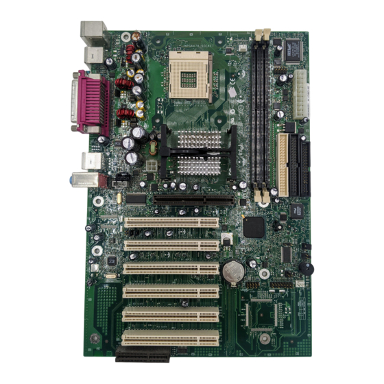
Intel Desktop Boards D845PT and D845BG Product Guide Figure 2 shows the location of the major components on the D845BG board. OM12624 Analog Devices Inc. AD1885 audio codec Diskette drive connector AGP connector Firmware Hub (FWH) CD-ROM connector (ATAPI) Intel 82801BA I/O Controller Hub (ICH2) -
Page 13: Processor
Failure to use an ATX12V power supply, or not connecting the additional power supply lead to the D845PT or D845BG boards may result in damage to the desktop board and/or power supply. The boards support a single Intel Pentium 4 processor. Processors are not included with the board and must be purchased separately. -
Page 14: Intel ® 845 Chipset
The D845PT and D845BG desktop boards have been designed to support DIMMs based on 512 Mbit technology up to 2 GB, but this technology has not been validated on these boards. For more information about the latest list of tested memory, refer to the Intel World Wide Web site at: http://support.intel.com/support/motherboards/desktop/ •... -
Page 15: Intel ® 82801Ba I/O Controller Hub (Ich2)
Intel 82801BA I/O Controller Hub (ICH2) The Intel 82801BA I/O Controller Hub integrates many I/O functions and provides the I/O subsystem with access to the rest of the platform. ICH2 features on D845PT and D845BG boards includes: • Integrated IDE controller supports two Ultra DMA-33 and ATA-66/100 channels, BMIDE and PIO modes •... -
Page 16: Usb Support
Ultra DMA-33 and ATA-66/100 protocols • Laser servo (LS-120) drives Expansion Slots The D845PT and D845BG boards have the following add-in card connectors: The D845PT board has: • Three PCI bus add-in card connectors (PCI bus connector 3 slot shared with CNR) •... -
Page 17: Accelerated Graphics Port (Agp)
✏ NOTE The D845PT and D845BG boards are only compatible with 1.5 V AGP cards. AGP is a high-performance interface for graphics-intensive applications, such as 3D graphics. AGP is independent of the PCI bus and is intended for exclusive use with graphical display devices. -
Page 18: Ide Auto Configuration
Supports RJ-45 connector with status indicator LEDs • Programmable transit threshold • Configurable EEPROM that contains the MAC address LAN Subsystem Software For LAN software and drivers, refer to the D845PT or D845BG link on Intel’s World Wide Web site at: http://support.intel.com/support/motherboards/desktop... -
Page 19: Rj-45 Lan Connector Leds
PME# wakeup support ACPI ACPI gives the operating system direct control over the power management and Plug & Play functions of a computer. The use of ACPI with the D845PT or D845BG board requires an operating system that provides full ACPI support. -
Page 20: Hardware
Intel Desktop Boards D845PT and D845BG Product Guide Hardware Power Connectors The D845PT and D845BG boards have two power connectors. See Figure 22 on page 70 for the location of the power connectors. Fan Connectors The D845PT and D845BG boards have one processor fan connector and two standard fan connectors. -
Page 21: Location Of Standby Power Indicator
Refer to the descriptions in and follow the steps outlined below: 1. Note the total D845PT or D845BG board standby current requirement. 2. Add to that the total PS/2 port standby current requirement if a wake-enabled device is connected. -
Page 22: Wake From Usb
PCI 2.2 slots (non-wake-enabled) CNR** (wake enabled) CNR** (non-wake-enabled) USB ports * Refer to the Intel Desktop Board D845PT/D845BG Technical Product Specification for the exact standby current requirements ** Dependent upon system configuration ✏ NOTE PCI requirements are calculated by totaling the following: •... -
Page 23: Installing And Replacing Desktop Board Components
2 Installing and Replacing Desktop Board Components This chapter tells you how to: • Install the I/O shield • Install and remove the desktop board • Install and remove a processor • Install and remove memory • Install and remove an AGP retention mechanism and card •... -
Page 24: Installing The I/O Shield
Intel Desktop Boards D845PT and D845BG Product Guide Installing the I/O Shield The board comes with an I/O shield. When installed in the chassis, the shield blocks radio frequency transmissions, protects internal components from dust and foreign objects, and promotes correct airflow within the chassis. -
Page 25: Installing And Removing The Desktop Board
Refer to your chassis manual for instructions on installing and removing the board. The D845PT board is secured to the chassis by six screws and the D845BG board by eight screws. See Figure 5 and Figure 6 for the locations of the mounting holes of each board. -
Page 26: D845Bg Board Mounting Holes
Intel Desktop Boards D845PT and D845BG Product Guide Figure 6 shows the location of the mounting holes for the D845BG board. OM12626 Figure 6. D845BG Board Mounting Holes... -
Page 27: Installing And Removing A Processor
Instructions on how to install the processor fan heatsink retention mechanism (RM) base and processor to the desktop board are given below. For instruction on how to install the processor fan heatsink, refer to the processor installation manual or the Intel customer support World Wide Web site: http://support.intel.com/support/processors/pentium4/intnotes478.htm... -
Page 28: Installing The Processor Fan Heatsink Rm Base To The Board
Intel Desktop Boards D845PT and D845BG Product Guide 3. Remove the four white pushpins from the RM base, if installed. 4. Align the four fasteners of the processor fan heatsink RM base (A) with the corresponding holes in the desktop board (B). Gently press down the four corners of the base until it snaps into place (see Figure 8). -
Page 29: Installing A Processor
4. Lower the lever to its original position. OM12078 Figure 10. Installing a Processor Installing the Processor Fan Heatsink For instructions on how to install the processor fan heatsink, refer to the boxed processor manual or the Intel World Wide Web site at: http://support.intel.com/support/processors/pentium4/intnotes478.htm... -
Page 30: Connecting The Processor Fan Heatsink Cable
Intel Desktop Boards D845PT and D845BG Product Guide Connecting the Processor Fan Heatsink Cable Connect the processor fan heatsink cable to the processor fan connector (see Figure 11). OM12630 Figure 11. Connecting the Processor Fan Heatsink Cable to the Processor Fan Connector... -
Page 31: Installing And Removing Memory
Installing and Replacing Desktop Board Components Installing and Removing Memory CAUTION To be fully compliant with all applicable Intel SDRAM memory specifications, the boards require DIMMs that support the Serial Presence Detect (SPD) data structure. You can access the PC Serial Presence Detect Specification at: http://www.intel.com/technology/memory/pcsdram/spec/... -
Page 32: Removing Dimms
Intel Desktop Boards D845PT and D845BG Product Guide OM12631 Figure 12. Installing a Memory Module 5. Make sure the clips at either end of the DIMM socket(s) are pushed outward to the open position. 6. Holding the DIMM by the edges, remove it from its anti-static package. -
Page 33: Installing And Removing The Agp Retention Mechanism And Card
AGP card RM, follow the instructions on page 36. ✏ NOTE All D845PT and D845BG boxed desktop boards may not include an AGP RM. See “Installing an AGP Card” on page 35 if your boxed desktop board does not include an AGP RM. OM10592... -
Page 34: Installing The Agp Card Retention Mechanism
Intel Desktop Boards D845PT and D845BG Product Guide The AGP card RM (see Figure 14) encloses the board’s AGP connector and stabilizes the AGP card. Place the board (component side up) on a flat, supportive surface, preferably on the anti-static bag in which the board was shipped. Follow the steps outlined below to attach the RM (A) to the AGP connector (B): 1. -
Page 35: Installing An Agp Card
Installing and Replacing Desktop Board Components Installing an AGP Card Follow these instructions to install an AGP card: 1. Place the AGP card in the AGP connector. 2. Press down on the card until it is completely seated in the AGP connector and the card retention notch snaps into place around the RM pin. -
Page 36: Removing The Agp Card Retention Mechanism
Intel Desktop Boards D845PT and D845BG Product Guide Removing the AGP Card Retention Mechanism Follow these instructions to remove the AGP card retention mechanism: 1. Using diagonal cutters (A), cut the loop (B) joining the two sides of the retention mechanism (see Figure 16). -
Page 37: Connecting The Ide Cable
Installing and Replacing Desktop Board Components Connecting the IDE Cable ® The Intel boxed desktop board package include an IDE cable. The cable connects two drives to the desktop board. The cable supports the Ultra DMA-33 and ATA-66/100 transfer protocols. -
Page 38: Setting The Bios Configuration Jumper Block
Intel Desktop Boards D845PT and D845BG Product Guide Setting the BIOS Configuration Jumper Block CAUTION Always turn off the power and unplug the power cord from the computer before changing the jumper. Moving the jumper with the power on may result in unreliable computer operation. -
Page 39: Clearing Passwords
Installing and Replacing Desktop Board Components Clearing Passwords This procedure assumes that the board is installed in the computer and the configuration jumper block is set to normal mode. 1. Observe the precautions in “Before You Begin” on page 23. 2. -
Page 40: Replacing The Battery
Intel Desktop Boards D845PT and D845BG Product Guide Replacing the Battery A coin-cell battery (CR2032) powers the real-time clock and CMOS memory. When the computer is not plugged into a wall socket, the battery has an estimated life of three years. When the computer is plugged in, the standby current from the power supply extends the life of the battery. - Page 41 Installing and Replacing Desktop Board Components VORSICHT Bei falschem Einsetzen einer neuen Batterie besteht Explosionsgefahr. Die Batterie darf nur durch denselben oder einen entsprechenden, vom Hersteller empfohlenen Batterietyp ersetzt werden. Entsorgen Sie verbrauchte Batterien den Anweisungen des Herstellers entsprechend. (German) AVVERTIMENTO Esiste il pericolo di un esplosione se la pila non viene sostituita in modo corretto.
-
Page 42: Removing The Battery
Intel Desktop Boards D845PT and D845BG Product Guide To replace the battery, follow these steps: 1. Observe the precautions in “Before You Begin” (see page 23). 2. Turn off all peripheral devices connected to the computer. Disconnect the computer’s power cord from the ac power source (wall outlet or power adapter). -
Page 43: Updating The Bios
1. Go to the Intel customer support World Wide Web site: http://support.intel.com/support/motherboards/desktop/ 2. Navigate to the D845PT or D845BG page and click the Express BIOS Update utility file for the D845PT or D845BG board’s BIOS. 3. Download the file to your hard drive. (You can also save this file to a diskette. This is useful if you are updating the BIOS for multiple identical systems.) -
Page 44: Updating The Bios With The Intel ® Flash Memory Update Utility
Flash Memory Update Utility With the Intel Flash Memory Update Utility you can update the system BIOS from a floppy disk or other bootable media. The utility available from the Web provides a simple method for creating a bootable flash memory update floppy that will automatically update your BIOS. -
Page 45: Recovering The Bios
Updating the BIOS Recovering the BIOS It is unlikely that anything will interrupt the BIOS update; however, if an interruption occurs, the BIOS could be damaged. The following steps explain how to recover the BIOS if an update fails. The following procedure uses recovery mode for the Setup program. See page 38 for more information on Setup modes. - Page 46 Intel Desktop Boards D845PT and D845BG Product Guide...
-
Page 47: Using The Setup Program
* For information about the BIS, refer to the Intel World Wide Web site: http://developer.intel.com/design/security/index1.htm... -
Page 48: Maintenance Menu
Invokes the Extended Configuration submenu. Configuration CPU Stepping No options Displays CPU’s Stepping Signature. Signature CPU Microcode No options Displays CPU’s Microcode Update Revision. Update Revision * For information about the BIS, refer to the Intel Web site at: http://developer.intel.com/design/security/index1.htm... -
Page 49: Extended Configuration Submenu
Using the Setup Program Extended Configuration Submenu Main Advanced Security Power Boot Exit Maintenance Extended Configuration This submenu shown in Table 9 is used to set system control and video memory cache mode. This submenu becomes available when User Defined is selected under Extended Configuration. Table 9. -
Page 50: Main Menu
Intel Desktop Boards D845PT and D845BG Product Guide Main Menu Maintenance Advanced Security Power Boot Exit Main Table 10 describes the Main Menu. This menu reports processor and memory information and is used to configure the system date and system time. -
Page 51: Advanced Menu
Using the Setup Program Advanced Menu Maintenance Main Security Power Boot Exit Advanced PCI Configuration Boot Configuration Peripheral Configuration IDE Configuration Diskette Configuration Event Log Configuration Video Configuration Table 11 describes the Advanced Menu. This menu is used to set advanced features that are available through the chipset. -
Page 52: Pci Configuration Submenu
• 11 PCI Slot 5 IRQ Priority No options Always set to Auto. (Note) PCI Slot 6 IRQ Priority No options Always set to Auto. (Note) Note: PCI slots 4, 5, and 6 are available only on the D845BG board. -
Page 53: Boot Configuration Submenu
Using the Setup Program Boot Configuration Submenu Maintenance Main Security Power Boot Exit Advanced PCI Configuration Boot Configuration Peripheral Configuration IDE Configuration Diskette Configuration Event Log Configuration Video Configuration The submenu shown in Table 13 is used to set the Plug & Play options, reset configuration data, and the power-on state of the Numlock key. -
Page 54: Peripheral Configuration Submenu
Intel Desktop Boards D845PT and D845BG Product Guide Peripheral Configuration Submenu Maintenance Main Security Power Boot Exit Advanced PCI Configuration Boot Configuration Peripheral Configuration IDE Configuration Diskette Configuration Event Log Configuration Video Configuration This submenu shown in Table 14 is used for configuring computer peripherals. -
Page 55: Dma Channels
Using the Setup Program Table 14. Peripheral Configuration Submenu (continued) Feature Options Description • Disabled Parallel Port Configures the parallel port. • Enabled Auto assigns LPT1 the address 378h and the interrupt IRQ7. • Auto (default) An * (asterisk) displayed next to an address indicates a conflict with another device. -
Page 56: Ide Configuration Submenu
Intel Desktop Boards D845PT and D845BG Product Guide IDE Configuration Submenu Maintenance Main Security Power Boot Exit Advanced PCI Configuration Boot Configuration Peripheral Configuration IDE Configuration Diskette Configuration Event Log Configuration Video Configuration This submenu shown in Table 15 is used to configure IDE device options. -
Page 57: Primary/Secondary Ide Master/Slave Submenus
Using the Setup Program Primary/Secondary IDE Master/Slave Submenus Maintenance Main Security Power Boot Exit Advanced Boot Configuration Peripheral Configuration Primary IDE Master ➜ IDE Configuration Diskette Configuration Primary IDE Slave Event Log Configuration Secondary IDE Master Secondary IDE Slave Video Configuration There are four IDE submenus: Primary master, primary slave, secondary master, and secondary slave. -
Page 58: Diskette Configuration Submenu
Intel Desktop Boards D845PT and D845BG Product Guide Table 16. Primary/Secondary IDE Master/Slave Submenus (continued) Feature Options Description • Disabled (default) Specifies the Ultra DMA mode for the drive. Ultra DMA • Mode 0 • Mode 1 • Mode 2 •... -
Page 59: Event Log Configuration Submenu
Using the Setup Program Event Log Configuration Submenu Maintenance Main Security Power Boot Exit Advanced PCI Configuration Boot Configuration Peripheral Configuration IDE Configuration Diskette Configuration Event Log Configuration Video Configuration The submenu shown in Table 18 is used to configure the event logging features. Table 18. -
Page 60: Video Configuration Submenu
Intel Desktop Boards D845PT and D845BG Product Guide Video Configuration Submenu Maintenance Main Security Power Boot Exit Advanced PCI Configuration Boot Configuration Peripheral Configuration IDE Configuration Diskette Configuration Event Log Configuration Video Configuration The submenu shown in Table 19 is used to configure video features. -
Page 61: Security Menu
Using the Setup Program Security Menu Maintenance Main Advanced Power Boot Exit Security The menu shown in Table 20 is used to set passwords and security features. Table 20. Security Menu If no password entered previously: Feature Options Description Supervisor Password Is No options Reports if there is a supervisor password set. -
Page 62: Power Menu
Intel Desktop Boards D845PT and D845BG Product Guide Power Menu Maintenance Main Advanced Security Boot Exit Power The menu shown in Table 21 is used to set power management features. Table 21. Power Menu Feature Options Description ACPI No Options When selected, displays the ACPI submenu. -
Page 63: Boot Menu
Disabled displays normal POST messages. • Enabled (default) Enabled displays OEM graphic instead of POST messages. • Disabled ® Intel Rapid BIOS Boot Enables the computer to boot without running certain POST tests. • Enabled (default) • Disabled (default) Scan User Flash Area Enables the BIOS to scan the flash memory for user binary files that are executed at boot time. -
Page 64: Boot Device Priority Submenu
After the predefined boot device types (removable devices, hard drives, and ATAPI CD-ROM drives), the entries in this list will reflect as many boot entry vector (BEV) boot devices (for example, Intel UNDI, PXE devices) and SCSI CD-ROM drives as are installed, up to the five BEV boot devices supported by the BIOS. -
Page 65: Hard Disk Drives Submenu
Using the Setup Program Hard Disk Drives Submenu Maintenance Main Advanced Security Power Boot Exit Boot Device Priority Hard Disk Drives Removable Devices ATAPI CD-ROM Drives The submenu shown in Table 25 is for setting hard disk drives. Table 25. Hard Disk Drives Submenu Feature Options... -
Page 66: Atapi Cd-Rom Drives
Intel Desktop Boards D845PT and D845BG Product Guide ATAPI CD-ROM Drives Maintenance Main Advanced Security Power Boot Exit Boot Device Priority Hard Disk Drives Removable Devices ATAPI CD-ROM Drives The submenu shown in Table 27 is for setting ATAPI CD-ROM drives. -
Page 67: Technical Reference
5 Technical Reference Board Connectors The board connectors can be divided into three groups: • Back panel connectors • Midboard connectors Audio connectors Power and hardware connectors Add-in board and peripheral interface connectors • Front panel connectors CAUTION Many of the midboard and front panel connectors provide operating voltage (+5 V dc and +12 V dc, for example) to devices inside the computer chassis, such as fans and internal... -
Page 68: Back Panel Connectors
Intel Desktop Boards D845PT and D845BG Product Guide Back Panel Connectors Figure 20 shows the back panel connectors on the board. OM12636 Item Description Color PS/2 mouse port Green PS/2 keyboard port Purple USB port 0 Black USB port 1... -
Page 69: Midboard Connectors
Technical Reference Midboard Connectors Audio Connectors Figure 21 shows the location of the audio connectors. OM12637 Item Description Color Front panel audio (see Table 29 for pin assignments) Black Auxiliary line in White CD-ROM Black Figure 21. Audio Connectors Table 29 shows the pin assignments for the front panel audio connector. Table 29. -
Page 70: Power And Hardware Connectors
The D845PT and D845BG boards require an ATX12V compliant power supply to function according to desktop board specifications. Both boards have two ATX12V compliant power supply connectors that are needed to provide extra power to the Intel 845 chipset and Pentium 4 processor. Figure 22 shows the power and hardware connectors. -
Page 71: Add-In Card And Peripheral Interface Connectors
Technical Reference Add-In Card and Peripheral Interface Connectors Figure 23 shows the add-in card and peripheral interface connectors for the D845PT board. OM12639 Item Description Item Description CNR (optional) PCI bus connector 3 Secondary IDE PCI bus connector 2 Primary IDE PCI bus connector 1 Diskette drive Figure 23. -
Page 72: D845Bg Board Add-In Card And Peripheral Interface Connectors
Intel Desktop Boards D845PT and D845BG Product Guide Figure 24 shows the add-in card and peripheral interface connectors for the D845BG board. OM12640 Item Description Item Description CNR (optional) PCI bus connector 1 PCI bus connector 6 PCI bus connector 5... -
Page 73: Front Panel Connectors
Technical Reference Front Panel Connectors Figure 25 shows the location of the front panel connectors. OM12641 Item Description Front panel USB (see Table 31 for pin assignments) Front panel Alternate power/sleep LED Front panel audio Figure 25. Front Panel Connectors Table 31 shows the pin assignments for the front panel USB connectors. -
Page 74: Desktop Board Resources
Intel Desktop Boards D845PT and D845BG Product Guide Desktop Board Resources Memory Map Table 32. System Memory Map Address Range (decimal) Address Range (hex) Size Description 1024 K - 2097152 K 100000 - 7FFFFFF 2047 MB Extended Memory 960 K - 1024 K... -
Page 75: I/O Map
Technical Reference I/O Map Table 34. I/O Map Address (hex) Size Description 0000 - 000F 16 bytes DMA controller 0020 - 0021 2 bytes Programmable Interrupt Control (PIC) 0040 - 0043 4 bytes System timer 0060 1 byte Keyboard controller byte—reset IRQ 0061 1 byte System speaker... - Page 76 Intel Desktop Boards D845PT and D845BG Product Guide Table 34. I/O Map (continued) Address (hex) Description 96 contiguous bytes starting on a 128-byte ICH2 (ACPI + TCO) divisible boundary 64 contiguous bytes starting on a 64-byte D845PT and D845BG board resources...
-
Page 77: Interrupts
Technical Reference Interrupts Table 35. Interrupts System Resource I/O channel check Reserved, interval timer Reserved, keyboard buffer full Reserved, cascade interrupt from slave PIC COM2* COM1* LPT2 (Plug and Play option) / ** Diskette drive controller LPT1* Real time clock Onboard mouse port (if present, else user available) Reserved, math coprocessor Primary IDE (if present, else user available) - Page 78 Intel Desktop Boards D845PT and D845BG Product Guide...
-
Page 79: A Error Messages And Indicators
A Error Messages and Indicators The D845PT and D845BG boards report POST errors in two ways: • By sounding a beep code • By displaying an error message on the monitor BIOS Beep Codes The BIOS beep codes are listed in Table 36. The BIOS also issues a beep code (one long tone followed by two short tones) during POST if the video configuration fails (a faulty video card or no card installed) or if an external ROM module does not properly checksum to zero. -
Page 80: Bios Error Messages
Intel Desktop Boards D845PT and D845BG Product Guide BIOS Error Messages When a recoverable error occurs during the POST, the BIOS displays an error message describing the problem. Table 37. BIOS Error Messages Error Message Explanation GA20 Error An error occurred with Gate-A20 when switching to protected mode during the memory test. - Page 81 Error Messages and Indicators Table 37. BIOS Error Messages (continued) Error Message Explanation Memory Size Decreased Memory size has decreased since the last boot. If no memory was removed, then memory may be bad. Memory Size Increased Memory size has increased since the last boot. If no memory was added, there may be a problem with the system.
- Page 82 Intel Desktop Boards D845PT and D845BG Product Guide...
-
Page 83: B Regulatory Compliance
B Regulatory Compliance This appendix contains: • Safety standards, electromagnetic compatibility (EMC) regulations, and product certification markings for the D845PT and D845BG desktop boards. • Instructions and precautions for integrators who are installing this desktop board in a chassis. Safety Regulations This desktop board complies with the safety regulations stated in Table 38 when correctly installed in a compatible host system. -
Page 84: Product Certification Markings
The desktop boards have the following product certification markings: • UL joint US/Canada Recognized Component mark: consists of small c followed by a stylized backward UR and followed by a small US. Includes adjacent UL file number for Intel desktop boards: E210882 (component side). •... -
Page 85: Installation Precautions
Regulatory Compliance Installation Precautions When you install and test the desktop board, observe all warnings and cautions in the installation instructions. To avoid injury, be careful of: • Sharp pins on connectors • Sharp pins on printed circuit assemblies • Rough edges and sharp corners on the chassis •... -
Page 86: Ensure Electromagnetic Compatibility (Emc) Compliance
Intel Desktop Boards D845PT and D845BG Product Guide Ensure Electromagnetic Compatibility (EMC) Compliance Before computer integration, make sure that the power supply and other modules or peripherals, as applicable, have passed Class B EMC testing and are marked accordingly. In the installation instructions for the host chassis, power supply, and other modules pay close attention to the following: •... -
Page 87: Place Battery Marking
Use Only for Intended Applications All Intel desktop processor boards are evaluated as Information Technology Equipment (I.T.E.) for use in personal computers for installation in homes, offices, schools, computer rooms, and similar locations. The suitability of this product for other applications or environments, such as medical,... - Page 88 Intel Desktop Boards D845PT and D845BG Product Guide...
Need help?
Do you have a question about the D845BG and is the answer not in the manual?
Questions and answers