Intel D845GVSR User Manual
Hide thumbs
Also See for D845GVSR:
- Product manual (84 pages) ,
- User manual (35 pages) ,
- Quick reference (20 pages)
Table of Contents
Advertisement
Quick Links
User' s Guide
D845GVSR Motherboard
All manuals and user guides at all-guides.com
C C O O N N T T E E N N T T S S
Chapter 1
Motherboard Description
Motherboard Overview
Chapter 2
Using the BIOS Setup Program
About the Setup Program
Entering the Setup Program
BIOS Setup Program
Chapter 3
Installing Board Options
Before You Begin
Installing and Removing the Processor
Installing and Removing Memory Modules
Changing the Jumpers
Replacing the Battery
The Things to do in Post-installation
Appendix A Specifications
Specifications
A-1
1-3
2-1
2-2
2-4
3-1
3-2
3-5
3-7
3-8
3-9
Rev. B
Advertisement
Table of Contents

Related Manuals for Intel D845GVSR


Summary of Contents for Intel D845GVSR
- Page 1 All manuals and user guides at all-guides.com Rev. B User’ s Guide D845GVSR Motherboard C C O O N N T T E E N N T T S S Chapter 1 Motherboard Description Motherboard Overview Chapter 2 Using the BIOS Setup Program...
- Page 2 All manuals and user guides at all-guides.com...
- Page 3 All manuals and user guides at all-guides.com Safety Information Battery Warning Instruction Caution If battery is incorrectly replaced there poses a danger of explosion. Replace battery only with the same or equivalent type recommended by the manufacturer. Discard used batteries according to the manufacturer’s instructions.
- Page 4 All manuals and user guides at all-guides.com Before You Read The information in this user’s guide is subject to change without notice. eMachines, Inc. shall not be liable for technical or editorial errors or omissions contained herein; nor for incidental or consequential damages resulting from the furnishing, performance, or use of this material. eMachines, stylized “e”...
-
Page 5: Table Of Contents
All manuals and user guides at all-guides.com CONTENTS Chapter 1 Motherboard Description Motherboard Overview .................... 1-3 Rear Panel Connectors ..................1-4 Chapter 2 Using the BIOS Setup Program About the Setup Program ..................2-1 Entering the Setup Program ..................2-2 Help Window .................... - Page 6 All manuals and user guides at all-guides.com Chapter 3 Installing Board Options Before You Begin ....................3-1 Installing and Removing the Processor ..............3-2 Installing the Processor ..................3-2 Removing the Processor .................. 3-4 Installing and Removing Memory Modules ............3-5 Installing a Memory Module ................
- Page 7 Intel ® 82845GV Graphics Memory Controller Hub (GMCH) Intel ® 82801DB I/O Controller Hub (ICH4) Built-in high performance audio CODEC and PCI audio controller in Intel ® 82845GV GMCH NSC PC87372 super I/O controller Intel ® 82562ET 10/100 Mbps (PLC) device...
-
Page 8: Chapter 1 Motherboard Description
All manuals and user guides at all-guides.com NOTE The internal graphics device on Intel 82845GV supports Intel Dynamic Video Memory Technology (D.V.M.T). D.V.M.T. dynamically responds to application requirements by allocating the proper amount of display and texturing memory. As your system has sharing memory architecture using the main memory for video memory, the usable main memory size is less than real size when the computer is running. -
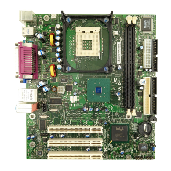
Page 9: Motherboard Overview
All manuals and user guides at all-guides.com Motherboard Overview mPGA478 socket Intel 82845GV Graphics Memory Rear chassis fan connector Controller Hub(GMCH) CPU fan connector Auxiliary 12V power supply connector DIMM sockets NSC PC87372 super I/O controller Power supply connector Back panel... -
Page 10: Rear Panel Connectors
All manuals and user guides at all-guides.com Rear Panel Connectors The motherboard has connectors for peripheral devices. LAN connector Parallel port connector Line-in jack USB connectors PS/2 mouse connector Line-out jack PS/2 keyboard connector Microphone jack Serial port (COM1) connector USB connectors Video connector Motherboard Description... -
Page 11: Chapter 2 Using The Bios Setup Program
All manuals and user guides at all-guides.com Using the BIOS Setup Program Using the BIOS Setup Program This chapter explains how to use the BIOS Setup program. You can use the Setup program to change the computer’s configuration information and boot-up sequence, etc. About the Setup Program Your system uses a Phoenix BIOS, which is stored in flash memory on the motherboard. -
Page 12: Entering The Setup Program
All manuals and user guides at all-guides.com Entering the Setup Program To enter the Setup program, turn the computer on and press DEL as soon as you see the “emachines” logo. If you do not press the key quickly, the computer starts loading the operating system. NOTE For reference purposes, write down the current Setup settings. -
Page 13: Help Window
All manuals and user guides at all-guides.com The next table shows the function keys available for menu screens. Setup Key Description <F1> or <Alt-H> Brings up a help screen for the current item. <Esc> Exits the menu. < > or < > Selects a different menu screen. -
Page 14: Bios Setup Program
All manuals and user guides at all-guides.com BIOS Setup Program Main Menu This menu reports processor and memory information and is for configuring the system date, system time, floppy options, and IDE devices. Feature Options Description BIOS Revision No options Displays the BIOS revision. -
Page 15: Advanced Menu
All manuals and user guides at all-guides.com Advanced Menu This menu is for setting advanced features that are available through the chipset. Feature Options Description Boot Configuration No options Configures Plug and Play. When selected, displays the Boot Configuration submenu. Peripheral Configuration No options Configures peripheral ports and devices. - Page 16 All manuals and user guides at all-guides.com Peripheral Configuration Submenu This submenu is for configuring peripheral ports and devices. Feature Options Description Serial Port A • Disabled Configures serial port A. • Enabled Auto assigns the first free COM port, normally COM1, the address 3F8h, •...
- Page 17 All manuals and user guides at all-guides.com Primary/Secondary IDE Master/Slave Submenus Feature Options Description Drive Installed No options Displays the type of drive installed. Type • Auto Specifies the IDE configuration mode for IDE devices. User allows • User capabilities to be changed. Auto fills-in capabilities from ATA/ATAPI device.
- Page 18 All manuals and user guides at all-guides.com Video Configuration Submenu This submenu is for configuring video features. Feature Options Description AGP Aperture Size • 4MB Sets the aperture size for the video controller. • 8MB • 16MB • 32MB • 64MB •...
-
Page 19: Security Menu
All manuals and user guides at all-guides.com Security Menu This menu is for setting passwords and security features. Feature Options Description Set Supervisor Password can be up Specifies the supervisor password. Password to seven alphanumeric characters. Set User Password Password can be up Specifies the user password. -
Page 20: Power Menu
All manuals and user guides at all-guides.com Power Menu This menu is for setting power features. Feature Options Description ACPI No options Sets the ACPI power management options. When selected, displays the ACPI submenu. ACPI Submenu This submenu is for configuring the ACPI power options. Feature Options Description... - Page 21 All manuals and user guides at all-guides.com Boot Device Priority Submenu You can select the boot sequence from the available devices. To specify boot sequence: 1. Select the boot device with < > or < >. 2. Press <+> to move the device up the list or <-> to move the device down the list. Hard Disk Drives Submenu This submenu is for setting hard disk drive priority.
-
Page 22: Exit Menu
All manuals and user guides at all-guides.com ATAPI CD-ROM Drives Submenu This submenu is for setting ATAPI CD-ROM drive priority. Feature Options Description 1st Drive Dependent on Specifies the boot sequence from the available ATAPI CD-ROM drives. installed To specify boot sequence: ATAPI CD-ROM 1. -
Page 23: Chapter 3 Installing Board Options
All manuals and user guides at all-guides.com Installing Board Options Installing Board Options This chapter describes how to install board options in your computer. You can use these instructions to install a variety of devices and board options. Although your board options may look a bit different from the ones illustrated herein, you can install and remove it the same way. -
Page 24: Installing And Removing The Processor
All manuals and user guides at all-guides.com Installing and Removing the Processor The processor that you install must be compatible with mPGA478 socket. Installing the Processor To install the processor, follow these steps: 1. See the illustration in “Motherboard Overview” in Chapter 1 for the location of the processor socket. - Page 25 All manuals and user guides at all-guides.com 4. Press the ZIF handle back to close it. 5. Attach the heatsink to the processor socket. NOTE Depending on the model, the heatsink may vary. 6. Connect the fan connector cable from the CPU fan to the CPU fan connector on the motherboard.
-
Page 26: Removing The Processor
All manuals and user guides at all-guides.com Removing the Processor To remove the processor, follow these steps: 1. Unplug the cable connector from the CPU fan connector on the motherboard. CPU fan connector 2. Remove the heatsink by releasing both tabs on the heatsink that secure the heatsink to the socket. -
Page 27: Installing And Removing Memory Modules
All manuals and user guides at all-guides.com 3. Pull the ZIF handle sideways away from the socket then upward to 90-degree angles and carefully pull the chip straight up from the socket. ZIF handle 4. Press the ZIF handle back to close it. Installing and Removing Memory Modules The motherboard has two dual inline memory module (DIMM) sockets. -
Page 28: Installing A Memory Module
All manuals and user guides at all-guides.com Installing a Memory Module Follow these steps to install DIMMs: 1. Release the plastic retaining clips at each end of the socket by pressing the clips outward until they snap open. 2. Orient a DIMM to the socket so the notch in the DIMM connector are aligned with the crossbars in the socket. -
Page 29: Changing The Jumpers
All manuals and user guides at all-guides.com Changing the Jumper The jumper is a small electrical connector that control circuit or function in your system. Jumper is a small block on a circuit board with two or more pins emerging from them. To change a jumper setting, pull the plug off its pins and carefully fit it down onto the pins indicated. -
Page 30: Replacing The Battery
All manuals and user guides at all-guides.com Replacing the Battery The 3 V, coin-cell CR2032-type battery on the mainboard provides power to the real-time clock and CMOS RAM. It has an estimated lifetime of three years if the computer is turned off. To replace the battery, follow these steps: 1. -
Page 31: The Things To Do In Post-Installation
All manuals and user guides at all-guides.com The Things to do in Post-installation After you install or remove board options, if necessary, be sure to run Setup program to update the configuration of your system. See Chapter 2 for detail information. If you installed a new optional equipment and Windows has installed in your system, you need to have Windows detects it. - Page 32 All manuals and user guides at all-guides.com Blank 3-10 Installing Board Options...
-
Page 33: Appendix A Specifications
• Each slot supports up to 1 GB memory of 200/266/333 MHz Non-ECC • Unbuffered DDR Synchronous DRAM (DDR SDRAM) Video memory • Use main memory (Intel Dynamic Video Memory Technology) NOTE As your system has sharing memory architecture using the main memory for video... -
Page 34: Specifications
• Four analog line-level stereo inputs for connection from LINE IN, CD, VIDEO and AUX • Advanced power management Built-in LAN Integrated LAN Media Access Controller in Intel ® 82801DB I/O Controller Hub (ICH4) Controller • PCI Bus Master interface •...
Need help?
Do you have a question about the D845GVSR and is the answer not in the manual?
Questions and answers