Table of Contents
Advertisement
G
S
ETTING
TARTED
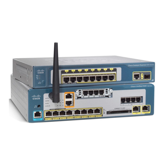
Cisco Unified Communications 500 Series Model UC 520
INCLUDING LICENSE AND WARRANTY
1
Cisco One-Year Limited Hardware Warranty Terms
2
Overview
3
Equipment
4
Installing the Chassis and Power Supply
5
Grounding the Chassis
6
Connecting the Power
7
Powering Up the System
8
Creating the Initial Software Configuration
9
Installing a Cisco Catalyst Express 520 for a UC 520
10
Connecting the Interfaces and Devices
11
Verifying the Communications
12
Modifying the Software Configuration
13
Related Documentation
G
UIDE
Advertisement
Table of Contents

Related Manuals for Cisco UC520-24U-8FXO-K9


Summary of Contents for Cisco UC520-24U-8FXO-K9
- Page 1 Installing the Chassis and Power Supply Grounding the Chassis Connecting the Power Powering Up the System Creating the Initial Software Configuration Installing a Cisco Catalyst Express 520 for a UC 520 Connecting the Interfaces and Devices Verifying the Communications Modifying the Software Configuration Related Documentation...
-
Page 2: Cisco One-Year Limited Hardware Warranty Terms
There are special terms applicable to your hardware warranty and various services that you can use during the warranty period. Your formal Warranty Statement, including the warranties and license agreements applicable to Cisco software, is available on Cisco.com. Follow these steps to access and download your warranty and license agreements from Cisco.com. - Page 3 One (1) Year Replacement, Repair, or Refund Policy for Hardware Cisco or its service center will use commercially reasonable efforts to ship a replacement part within ten (10) working days after receipt of a Return Materials Authorization (RMA) request. Actual delivery times can vary, depending on the customer location.
- Page 4 Figure 1 shows the typical deployment of a Cisco Unified 500 Series in a Cisco Smart Business Communications System. The Cisco Smart Business Communications System is a unified communications solution for small businesses that provides voice, data, video, security, and wireless capabilities while integrating with existing desktop applications like calendar, e-mail, and Customer Relationship Management (CRM).
-
Page 5: Table
4 FXS, 4 FXO or 2 BRI 8 PoE, and 8 PoE, and UC520-16U-2BRI-K9 4 FXO or 2 BRI 4 FXO or 2 BRI UC520W-16U-2BRI-K9 UC520-24U-8FXO-K9 4 FXS, SIP trunk, 4 FXS/DID, UC520-24U-4BRI-K9 8 PoE, and 4 FXS, 8 PoE, and... - Page 6 Table 2 UC 520 Interfaces Value in Software Description Label Configuration Console/Aux port CONSOLE — Fast Ethernet 10/100 expansion port EXPANSION FastEthernet0/1/8 Fast Ethernet 10/100 WAN port FastEthernet0/0 Fast Ethernet 10/100 Power over Ethernet Power Over Ethernet, and FastEthernet0/1/0 to 0/1/7 (PoE) ports PWR 0 LNK to PWR 7 FXS (Foreign Exchange Station) ports...
-
Page 7: Software Components
Table 3 lists the labels and descriptions for the interfaces on a Cisco Catalyst Express 520, along with the values for these interfaces in the software configuration on the UC 520. Table 3 Cisco Catalyst Express 520 Switch: Interfaces Value in Software... - Page 8 All files and configurations for IP Communications Manager that provides a wide range of IP phones are stored internally on Express (Cisco Unified CME) telephony features for small to the UC 520 for a cost-effective, medium-sized business highly reliable, IP customers and autonomous small communications solution.
- Page 9 Table 5 UC 520 Software Components (continued) Software Component Description Benefits Cisco Secure VPN Carries private data over a public Most cost-effective method to network and extends remote provide increased VPN access to users over a shared throughput with minimal effect infrastructure.
-
Page 10: Uc520-48U-T/E/F-K9
License Support Table 6 lists the maximum number of phones and devices supported in Cisco Unified CME, based on licensing and organized by model. Table 6 Cisco Unified CME License Support Cisco Unified CME Maximum Devices (Wired and UC 520 Models... -
Page 11: Table Of Contents
Table 7 lists the maximum numbers of mailboxes supported on the UC 520, based on licensing and organized by model. Table 7 Cisco Unity Express License Support General Delivery Mailboxes UC 520 Models Mailboxes (GDMs) UC520-8U-4FXO-K9 12 + 2 for teleworkers... - Page 12 Wall-mount bracket for power supply (included with 8- and 16-user models only) – Rack-mount brackets for chassis (included with 32- and 48-user models only) – Getting Started Guide for Cisco Unified Communications 500 Series Model UC 520 for Small – Business (this guide) Cisco Smart Business Communications System Setup –...
- Page 13 Figure 5 for the 24-, 32- and 48-user models. Figure 2 UC 520 with FXO Ports (8- and 16-user model) Cisco Unified 500 Series Figure 3 UC 520 with FXO Ports (24-, 32- , and 48-user model) Cisco Unified 500...
- Page 14 FXO ports (Optional) Factory-installed VIC or T1/E1 VWIC Compact Flash slot Figure 4 UC 520 with BRI Ports (8- and 16-user model) Cisco Unified 500 Series Music-on-hold (MoH) port Expansion port Console/Aux port FXS ports Power over Ethernet (PoE) ports...
- Page 15 Cisco Product Identification Tool The Cisco Product Identification tool provides detailed illustrations and descriptions showing where to find serial number labels on Cisco products. It includes the following features: • A search option that allows browsing for models using a tree-structured product hierarchy •...
-
Page 16: Safety Information
Rack-Mounting Safety Information The Regulatory Compliance and Safety Information document for Cisco Unified 500 Series contains translations of the warnings that appear in this guide. For safety information you must know before working on the UC 520, see the Regulatory Compliance... - Page 17 Warning Definitions Warning IMPORTANT SAFETY INSTRUCTIONS This warning symbol means danger. You are in a situation that could cause bodily injury. Before you work on any equipment, be aware of the hazards involved with electrical circuitry and be familiar with standard practices for preventing accidents.
- Page 18 Warning To avoid electric shock, do not connect safety extra-low voltage (SELV) circuits to telephone-network voltage (TNV) circuits. LAN ports contain SELV circuits, and WAN ports contain TNV circuits. Some LAN and WAN ports both use RJ-45 connectors. Use caution when connecting cables. Statement 1021 Warning Hazardous network voltages are present in WAN ports regardless of whether power to the unit is OFF or ON.
- Page 19 Warning Ultimate disposal of this product should be handled according to all national laws and regulations. Statement 1040 Warning This equipment must be installed and maintained by service personnel as defined by AS/NZS 3260. Incorrectly connecting this equipment to a general-purpose outlet could be hazardous.
-
Page 20: Installation Guidelines
Before you install the UC 520, review the Regulatory Compliance and Safety Information for Cisco Unified Communications 500 Series for Small Business document on Cisco.com. This platform is a self-contained unit. Do not remove or install any modules or interface cards unless otherwise directed. - Page 21 To install a chassis on a desktop, table, or other flat surface, place the unit upside-down on a flat surface. Attach the four rubber pads to the recessed areas on the bottom of the unit. Place the unit on a desktop. Wall-Mounting (8- and 16-user models only) You can mount the unit and power supply to a wall or other vertical surface.
- Page 22 Figure 6 Wall-Mount Holes on the Bottom of the UC 520 8.318 in. (21.127 cm) Front panel Mounting-screw holes Align the mounting-screw holes with a wall stud, or use wall anchors. Step 2 a. For attaching to a wall stud, use two #10 wood screws (round- or pan-head) with #10 washers, or two #10 washer-head screws.
- Page 23 Figure 7 shows the wall-mount bracket for the power supply and the mounting-screw holes Step 4 on the back of the bracket. Align the mounting-screw holes with a wall stud, or use wall anchors. Figure 7 Wall-Mount Bracket for Power Supply a.
- Page 24 Step 1 Attach the mounting brackets to the sides of the chassis as shown in Figure 8, using the screws provided. Use four screws on each side. Use a number 2 Phillips screwdriver to install the bracket screws. Figure 8 Attaching Rack-Mount Brackets to the UC 520 Figure 9 shows the brackets in the rack-mount kit for the power supply.
- Page 25 Position the power supply in the wall-mount bracket. (This step applies only to the 8- and Step 3 16-user models.) a. Orient the front and back of the power supply vertically. b. Position the end nearest the power cable at the top. Assemble the brackets for rack-mounting the power supply as shown in Figure 10, using the...
-
Page 26: Grounding The Chassis
Be sure to leave space above and below each unit in a rack to allow for cooling air circulation. Note If you are deploying a single integrated wireless access point, connect the antenna to the front panel before you mount the unit on a wall. It is difficult to attach an antenna after the platform is mounted to a wall. - Page 27 Warning This equipment needs to be grounded. Use a green and yellow 14 AWG ground wire to connect the host to earth ground during normal use. Statement 190 To connect the chassis to a reliable earth ground, perform the following steps. Strip one end of the ground wire to the length required for the ground lug or terminal.
-
Page 28: Connecting The Power
Figure 12 Attaching the Ground to Chassis (24-, 32-, and 48-User Model) Grounding lug Step 4 Connect the other end of the ground wire to a known reliable earth ground point. If there is any doubt as to the reliability of the ground point, contact a licensed electrician for assistance. Connecting the Power Warning Only trained and qualified personnel should be allowed to install, replace, or service this... -
Page 29: Powering Up The System
Warning Do not work on the system or connect or disconnect cables during periods of lightning activity. Statement 1001 To connect the power supply to the UC 520, follow these steps: Step 1 Connect the AC power cord to the the power supply. Connect the power interface cable to the power connector port on the back of the unit. -
Page 30: Creating The Initial Software Configuration
Blinking green Connected Creating the Initial Software Configuration To use the Cisco Configuration Assistant to create and save the initial software configuration, follow these steps: If necessary, install Configuration Assistant on a PC to be used to manage the configuration Step 1 of the UC 520. - Page 31 Using an RJ-45-to-RJ-45 Ethernet cable, connect the Ethernet port of the PC on which the Step 3 Cisco Configuration Assistant is installed to a PoE port on the front panel of the UC 520. Use the Configuration Assistant to perform the following tasks. For more information, see Step 4 online help.
-
Page 32: Installing A Cisco Catalyst Express 520 For A Uc
“Installation Guidelines” section on page The warnings in this chapter are translated into different languages in the Regulatory Compliance and Safety Information for the Catalyst Express 520 Switches document on Cisco.com. This section contains basic installation information including the following: Warning Definitions •... - Page 33 Warning IMPORTANT SAFETY INSTRUCTIONS This warning symbol means danger. You are in a situation that could cause bodily injury. Before you work on any equipment, be aware of the hazards involved with electrical circuitry and be familiar with standard practices for preventing accidents.
- Page 34 Warning Ethernet cables must be shielded when used in a central office environment. Statement 171 Warning Do not work on the system or connect or disconnect cables during periods of lightning activity. Statement 1001 Warning Read the installation instructions before connecting the system to the power source.
- Page 35 Warning For connections outside the building where the equipment is installed, the following ports must be connected through an approved network termination unit with integral circuit protection: 10/100/1000 Ethernet. Statement 1044 Warning When installing or replacing the unit, the ground connection must always be made first and disconnected last.
- Page 36 • The heat sinks and the bottom of the Cisco Catalyst Express 520 switch might be hot to the touch if the switch is operating at its maximum temperature 113°F (45°C) and is in an environment that exceeds normal room temperature (such as a closet, a cabinet, or a closed or multirack assembly).
- Page 37 • Cabling is safely away from other devices that might damage the cables. Desktop Installation When installing a Cisco Catalyst Express 520 on a desktop, table, or shelf, observe the following precautions: Warning The plug-socket combination must be accessible at all times because it serves as the main disconnecting device.
- Page 38 After the Cisco Catalyst Express 520 switch successfully completes POST, disconnect the Step 5 power cord from the AC outlet and connect the switch to the UC 520. For detailed instructions on using the Cisco Catalyst Express 520 switch, see the User Guide for the Catalyst Express 520 Switches at: http://www.cisco.com/en/US/products/ps7238/tsd_products_support_series_home.html...
-
Page 39: Connecting The Interfaces And Devices
Step 4 a. Verify that the switch you just installed appears on the Topology View page. b. Add the Cisco Catalyst Express 520 switch to the Community for the UC 520. For more information, see the online help. Connecting the Interfaces and Devices... - Page 40 PBX. Connect the Devices To connect wireless access points, Cisco Unified IP phones, and other devices to a UC 520 or a Cisco Catalyst Express 520 switch, follow these steps in any order: Install and connect Cisco Unified IP phones to the PoE ports on the front panel of the UC 520 Step 1 and if installed, to PoE ports on front of the switch.
-
Page 41: Verifying The Communications
PC that is connected to the Step 2 UC 520. Test the PSTN by placing a call from a Cisco Unified IP phone that is connected to the UC 520 Step 3 to a number in the local calling area. -
Page 42: Modifying The Software Configuration
Go to the phone that you called. Verify that the [Message] indicator is lit. e. Press the [Message] button on a phone and retrieve the voice-mail message. If appropriate, repeat the previous steps using devices connected to the Cisco Catalyst Step 6 Express 520. - Page 43 Before deploying the system at the customer site, use the Cisco Configuration Assistant to create and save the initial configuration by accepting the default values. To stage a single-site key system configuration, change the Voice System Type setting from PBX (default) to Key System Configuration.
-
Page 44: Cisco Configuration Assistant
Cisco Configuration Assistant The Cisco Configuration Assistant is installed on a PC or laptop that is connected to the Cisco Unified Series by direct connection to a PoE port on the front panel of the platform, by connection to the LAN, or via VPN client. - Page 45 Cisco Unified CME Phone User Page The Cisco Unified CME phone user page enables phone users to program a small set of features on their own phones, such as changing speed dial buttons, and to search the Cisco Unified CME directory.
- Page 46 Note http://www.cisco.com/en/US/products/ps7293/prod_installation_guides_list.html. Prerequisites • The Cisco Configuration Assistant must be installed on a PC or laptop to be connected to the UC 520. For information, see the Getting Started with Cisco Configuration Assistant at http://www.cisco.com/go/configassist or on the CD-ROM that shipped with the product.
- Page 47 Express on a UC 520, you must download a language pack from Cisco.com. Prerequisites • Cisco Configuration Assistant must be installed on a PC or laptop to be connected to the UC 520. For information, see the Getting Started with Cisco Configuration Assistant at http://www.cisco.com/go/configassist...
- Page 48 CD-ROM that shipped with product. Using a RJ-45 to RJ-45 Ethernet cable, connect the Ethernet port of the PC on which the Cisco Step 5 Configuration Assistant is installed to a PoE port on the front panel of the unit.
- Page 49 • The Ethernet port of the PC is connected to a PoE port on the front panel of the UC 520 or the Cisco Catalyst Express 520 switch, or to the switch port on the back of a Cisco Unified IP phone that is connected to a PoE port on the platform or switch and is active, using an RJ-45 to RJ-45 Ethernet cable.
-
Page 50: Related Documentation
When the login screen appears, enter your username and password. User names and Step 2 passwords for individual phone users are defined by the office administrator using the Cisco Unified CME and Cisco Unity Express GUI. The home window appears. For information, see online help. - Page 51 Documentation Document Title Cisco Unity Express administrative and Cisco Unified Communications 500 Series for Small user documentation Business supports Cisco Unity Express Version 2.3.4 and higher releases. Cisco Unity Express Documentation, By Version at http://www.cisco.com/en/US/docs/voice_ip_comm/unity _exp/roadmap/cuedocs.html User documentation for Cisco Unified IP...
- Page 52 Tel: 31 0 800 020 0791 Fax: 408 527-0883 Fax: 31 0 20 357 1100 Cisco has more than 200 offices worldwide. Addresses, phone numbers, and fax numbers are listed on the Cisco Website at www.cisco.com/go/offices. © 2009 Cisco Systems, Inc. All rights reserved.
Need help?
Do you have a question about the UC520-24U-8FXO-K9 and is the answer not in the manual?
Questions and answers