Table of Contents
Advertisement
Quick Links
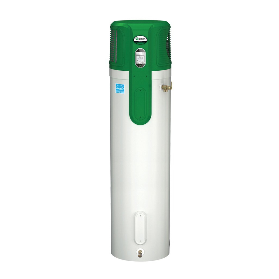
A.O. Smith - Voltex™
Hybrid Electric
Heat Pump Water Heater
Installation
Instructions and
Use & Care Guide
To obtain technical, warranty or service assistance during or after
the installation of this water heater, call toll free
1-800-527-1953
When calling for assistance, please have the following
information ready:
1. Model number
2. 7 Digit product number
3. Serial number
4. Date of installation
5. Place of Purchase
Table of Contents
Water Heater Safety ............................................................................... 2
Installing Your Water Heater ................................................................. 3-9
Installation Checklist .............................................................................. 10
Operating Your Water Heater ........................................................... 11-13
Maintenance of Your Water Heater .................................................. 14-15
Diagnostic Codes .................................................................................. 16
Troubleshooting Chart ........................................................................... 17
Repair Parts Illustration ......................................................................... 18
Notes... .............................................................................................. 19-20
Consumer Information ................................................................ 3
Consumer Responsibilities ......................................................... 3
Unpacking Instructions ............................................................ 3-4
Location Requirements ............................................................... 4
Water System Piping ................................................................ 5-6
Temperature & Pressure Relief Valve ....................................... 7-8
Electrical Requirements ........................................................... 8-9
Before Using ............................................................................. 11
Water Temperature Regulation ................................................. 11
Adjusting the User Interface Module/ Operational Mode .......... 12
Operational Conditions ............................................................. 13
Temperature and Pressure Relief Valve .................................... 14
Draining and Flushing ................................................................ 14
Heating Element Replacement ............................................. 14-15
Cleaning the Heat Pump ........................................................... 15
Page
318257-000
February 2010
1
Advertisement
Table of Contents

Related Manuals for A.O. Smith Voltex Hybrid Electric PHPT-80


Summary of Contents for A.O. Smith Voltex Hybrid Electric PHPT-80
-
Page 1: Table Of Contents
A.O. Smith – Voltex™ Hybrid Electric Heat Pump Water Heater Installation Instructions and Use & Care Guide To obtain technical, warranty or service assistance during or after the installation of this water heater, call toll free 1-800-527-1953 When calling for assistance, please have the following information ready: 1. -
Page 2: Water Heater Safety
WATER HEATER SAFETY Your safety and the safety of others are very important. We have provided many important safety messages in this manual and on your appliance. Always read and obey all safety messages. This is the safety alert symbol. This symbol alerts you to potential hazards that can kill or hurt you and others. -
Page 3: Installing Your Water Heater
INSTALLING YOUR WATER HEATER Consumer Information This water heater should be installed in accordance with the local code authority having jurisdiction, the power company or electric utility, and this installation manual. In the absence of local code requirements, follow the regulations set forth in the latest edition of The National Electric Code, NFPA 70. -
Page 4: Location Requirements
• The water heater must NOT be placed on its side. It should be transported and stored in an upright position. • Remove exterior packaging and place installation components aside. • Inspect all parts for damage prior to installation and start-up. -
Page 5: Water System Piping
Water System Piping Piping, fi ttings, and valves should be installed according to the installation drawing (Figure 4). If the indoor installation area is subject to freezing temperatures, the water piping must be properly insulated. Water supply pressure should be 50-60 PSIG and not exceed the maximum 80 PSIG. -
Page 6: Condensate Drain Line Installation
Please note the following: • The system should be installed only with piping that is suitable for potable (drinkable) water such as copper, CPVC, or polybutylene. This water heater must not be installed using iron piping or PVC water piping. •... -
Page 7: Temperature & Pressure Relief Valve
Temperature and Pressure Relief Valve WARNING Explosion Hazard If the temperature and pressure relief valve is dripping or leaking, have a qualified person replace it. Examples of a qualified person include: licensed plumbers, authorized electric company personnel, and authorized service personnel. -
Page 8: Electrical Requirements
Figure 6 T&P Relief Valve Insulation Manual Relief Lever T&P Relief Valve T&P Relief Valve Drain Line Locate the hot water (outlet) & cold water (inlet) pipes to the water heater. Locate the slit running the length of a section of pipe insulation. -
Page 9: Insulation Blankets
Figure 8A Junction Box Green Ground Wire Black Wire Red Wire Figure 8B Condensate Pump Wiring Condensate Pump Wiring Loop 18 AWG - White (Loop Located Behind Junction Box) White Wires From Water Heater Figure 9 Wiring Diagram Overload Protection Approved Connectors Black Green... -
Page 10: Installation Checklist
INSTALLATION CHECKLIST Water Heater Location □ Centrally located with the water piping system. □ The fl ooring beneath the water heater must be able to support the weight of the water heater when fi lled with water (967 lbs. full). □... -
Page 11: Operating Your Water Heater
OPERATING YOUR WATER HEATER Before Using Make sure the water heater has been properly installed. See “Installing Your Water Heater” section. Make sure the air filter is correctly seated, as it may shift during shipping or installation. See “Repair Parts Illustration”... -
Page 12: Adjusting The User Interface Module/ Operational Mode
Adjusting the User Interface Module/Operational Modes Water Temperature Adjustment The water temperature can be adjusted from 95°F to 150°F. Use the Up and Down Buttons panel to set the desired temperature. Before attempting to adjust the thermostat, IMPORTANT: read the “Water Temperature Regulation” section. If the instructions are not clear, contact a qualifi... -
Page 13: Operational Conditions
Operational Conditions Powered Anode Operation To shelter the glass-lined water tank from corrosion through electrolysis, this water heater is equipped with a non-sacrificial powered anode which should not need to be replaced under normal operating conditions. If the powered anode malfunctions it should be replaced by a qualified technician. -
Page 14: Maintenance Of Your Water Heater
MAINTENANCE OF YOUR WATER HEATER Temperature and Pressure Relief Valve WARNING Explosion Hazard If the temperature and pressure relief valve is dripping or leaking, have a qualified person replace it. Examples of a qualified person include: licensed plumbers, authorized electric company personnel, and authorized service personnel. -
Page 15: Cleaning The Heat Pump
Figure 12: Screws Remove the access cover(s), then remove the foam insulation block. Remove the protective plastic cover(s) over the elements from their attachment point. Disconnect the electrical wires from the heating element(s) by loosening the screws (Figure 12). Remove the screw-in element(s) by turning the element(s) counterclockwise with a 1-1/2 inch socket wrench. -
Page 16: Diagnostic Codes
DIAGNOSTIC CODES DISPLAY SHOWS UPPER ELEMENT CONNECT FAULT LOWER ELEMENT CONNECT FAULT HEAT PUMP CONNECT FAULT CONNECT FAULT AMBIENT TEMP SENSOR SHORT OR OPEN OR AD ERROR UPPER TEMP SENSOR SHORT OR OPEN OR AD ERROR LOWER TEMP SENSOR SHORT OR OPEN OR AD ERROR DISCHARGE TEMP SENSOR SHORT OR OPEN... -
Page 17: Troubleshooting Chart
TROUBLESHOOTING CHART PROBLEM NO HOT WATER INSUFFICIENT HOT WATER/ SLOW HOT WATER RECOVERY HIGH OPERATION COSTS DRIP FROM TEMPERATURE & PRESSURE RELIEF VALVE (Warning: Do not plug or cap T&P discharge pipe.) OTHER POSSIBLE CAUSE(S) Hot water usage pattern exceeds the capability of the water heater in current mode No power to the water heater... -
Page 18: Repair Parts Illustration
REPAIR PART ILLUSTRATION REPAIR PARTS Repair parts may be ordered through your plumber, local distributor, home improvement center, or by calling 1-800-527-1953. When ordering repair parts always give the following information: 1. Model, serial and product number 2. Item number 3. -
Page 19: Notes
NOTES... - Page 20 Copyright © 2010 A.O. Smith Corporation. All rights reserved.
Need help?
Do you have a question about the Voltex Hybrid Electric PHPT-80 and is the answer not in the manual?
Questions and answers