Table of Contents
Advertisement
Service Handbook
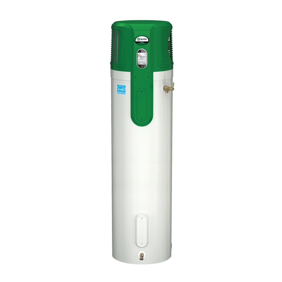
RESIDENTIAL HYBRID ELECTRIC HEAT PUMP WATER HEATER
FOR MODELS:
PHPT-60 (60 GAL.)
®
PHPT-80 (80 GAL.)
INSTALLATION CONSIDERATIONS -
PREVENTIVE MAINTENANCE -
OPERATION & SERVICE - TROUBLESHOOTING
SERVICE SHOULD ONLY BE PERFORMED BY A QUALIFIED SERVICE TECHNICIAN
PRINTED IN THE U.S.A. 0511
321547-000
Advertisement
Table of Contents
Troubleshooting

Related Manuals for A.O. Smith PHPT-60


Summary of Contents for A.O. Smith PHPT-60
- Page 1 Service Handbook RESIDENTIAL HYBRID ELECTRIC HEAT PUMP WATER HEATER FOR MODELS: PHPT-60 (60 GAL.) ® PHPT-80 (80 GAL.) INSTALLATION CONSIDERATIONS - PREVENTIVE MAINTENANCE - OPERATION & SERVICE - TROUBLESHOOTING SERVICE SHOULD ONLY BE PERFORMED BY A QUALIFIED SERVICE TECHNICIAN PRINTED IN THE U.S.A. 0511...
-
Page 2: Table Of Contents
Table of Contents Introduction ................................3 Certifi cation and Approvals ............................ 3 Tools Required............................... 3 Terms, Defi nitions, and Formulas .......................... 4 Safety Precautions ..............................5 Installation Check List............................6 Potential Issues ..............................7 Dry Fire Protection / Powered Anode Operation ....................8 Water Piping System ............................ -
Page 3: Introduction
Service Handbook Introduction: Your safety, and the safety of others, is extremely important in the servicing of this water heater. Many safety-related messages and instructions have been provided in this handbook and on your water heater to warn you and others of potential hazards. -
Page 4: Terms, Defi Nitions And Formulas
Terms, Defi nitions and Formulas First Hour Rating (FHR) is a volume of hot water delivered by a water heater during a 1-hour, Department Of Energy mandate test procedure. The FHR is given in gallons or liters. Energy Factor (EF) is an indicator of the combined thermal effi ciency and standby effi ciency of a water heater. -
Page 5: Safety Precautions
Safety Precautions Explosion Hazard WARNING Excessive Weight Hazard Use two or more people to move and install water heater. Failure to do so can result in back or other injury. -
Page 6: Installation Checklist
Installation Checklist Water Heater Location installed, see “Closed System/Thermal Expansion” section (p.10). • Centrally located with the water piping system. • Mixing valve (when applicable) installed per • The fl ooring beneath the water heater must be able manufacturer’s instructions see “Water Piping to support the weight of the water heater when System”... -
Page 7: Potential Issues
Potential Installation Issues Symptom Cause Solution Temperature set to 60 ºF and not Vacation mode is on Turn off Vacation mode by pressing adjustable the Vacation button Electric mode selected but the Upon initial start up, the heat No action is necessary. heat pump is running pump will run until the tank If after heat pump operation has... -
Page 8: Dry Fire Protection / Powered Anode Operation
Dry Fire Element Protection cleared before the water heater will operate. In order to Dry Fire is a term used to describe a heating element clear the error, shut off power to the water heater, and that is on and not fully submerged in water. This will purge all air from the water heater tank. -
Page 9: Water Piping System
Water Piping System 3. Some local codes may require, and the manufacturer of Piping, fi ttings, and valves should be installed according to this water heater recommends, installing a mixing valve the installation drawing (Figure 2). If the indoor installation or an anti-scald device in the domestic hot water line as area is subject to freezing temperatures, the water piping shown (Figure 2), or at the point of use. -
Page 10: T&P Valve / Thermal Expansion
Temperature and Pressure Relief Valve tubing so that any discharge from the valve exits only within 6 in. (152mm) above drain, or at any distance below, the structural fl oor, and does not contact any live electrical part. Explosion Hazard The discharge opening must not be blocked or reduced in size under any circumstance. -
Page 11: General Service / Preventive Maintenance
General Service information • Volts times Amps = Watts • Element Cycling: • Watts divided by Volts = Amps Most two-element water heaters are non- simultaneous. In other words, only one element • Replacement Elements: operates at a time. Use replacement elements that are rated at the If the upper element fails, the customer will lose hot same wattage, voltage and shape indicated on water. -
Page 12: Operational Overview
Operational Overview Vacation mode should be used when hot water will Heat Pump Water Heater Operation: not be needed for a period of time greater than three Heat pump water heaters remove heat from (3) days. In vacation mode electric elements are used surrounding air and use that heat to heat water. -
Page 13: Operating Your Heat Pump
Operating Your Heat Pump Water Heater Vacation Mode - The set point changes to 60°F Turning the Unit On: which is the temperature that will be VACATION maintained. This mode is recommended for The power button is located at the bottom of the UIM, periods of three (3) days or more in which the below the display. -
Page 14: Control Board Overview
Control Board Overview Figure 5 Heat Pump Water Heater Control Board Overview: The Control Board on the Heat Pump Water Heater monitors the complete heating system and reports any errors through the User Interface Module (UIM). Based on the inputs from the sensors and/or the manual inputs from the UIM, the Control Board determines which heating mode the unit should be in to reach the user set-point. -
Page 15: Control Board Section "A
Section “A” of Control Board Figure 6 Section “A” CN201 FUS201 FUS202 CN202 CN206 CN207 CN 201 Line Power: • Pin 1 - Control board power wire L1 (240VAC) • Pin 2 - Control board power wire L2 (240VAC) • Pin 3 - Not used •... -
Page 16: Control Board Section "B
Section “B” of Control Board Figure 7 Section “B” Pin 1 Pin 2 Terminal 1 Terminal 2 RY 203 Upper Element Relay: • Terminal 1 - COM Connects to L1 behind the ECO Switch. • Terminal 2 - NO Connects to the upper heating element. CN 203 Powered Anode: •... -
Page 17: Control Board Section "C
Section “C” of Control Board Section “C” Figure 8 CN 208 CN 211/215 Dip Switch CN 212 CN 204 CN 204 Upper and Lower tank water temperature sensors: • Pin 1 - Upper water temperature sensor on tank. • Pin 2 - Upper water temperature sensor on tank. •... -
Page 18: Control Board Section "D
Section “C” of Control Board (con’t) CN 211/215 UIM Communication Cable: • Pin 1 - +5 V • Pin 2 - +12 V • Pin 3 - Signal A+ • Pin 4 - Signal B+ • Pin 5 - Ground Note: Both CN211 and CN215 are identical and either can be used for the UIM communication. -
Page 19: Wiring Diagrams
Wiring Diagram for Models With Relay COIL TEMP. SENSOR HEAT PUMP WATER Figure 10 BLACK DISCHARGE TEMP. SENSOR HEATER WIRING DIAGRAM AMBIENT TEMP. SENSOR BLACK TANK LOWER TEMP. SENSOR TANK UPPER TEMP. SENSOR ANODE - POWERED GREEN DISPLAY GREEN CN215 CN203 CN204 CN211... -
Page 20: Wiring Diagrams
Wiring Diagram for Non-Relay Models Junction Box FIigure 11 Overload Circui Protectio Breaker Approved Connectors Black To 240v 1 Phase Green Power supply Ground Wire Electrical Service ground... -
Page 21: Accessing Maintenance Display
Accessing the Maintenance Display Interpreting the fault code history The User Interface Module on the front of the heat pump water heater has a multi-function display that Fault code E01 is the newest code detected. If there gives information about the status and condition of the is a fault shown on the User Display, E01 is the active operation of the water heater. -
Page 22: Element Test (Continuity Check)
E l ement Test (Continuity Tester) I. Preparing for the Test 1. Press the power button on the User Interface Module (UIM). 2. Turn off power to the water heater at the breaker or disconnect switch serving the water heater. 3. -
Page 23: Element Test (Ohm's Check)
E l ement Test (OhmMeter) I. Preparing for the Test 1. Press the power button on the User Interface Module. 1. Turn off power to the water heater at the breaker or disconnect switch serving the water heater. 2. Verify there is no power at the incoming power connections to the water heater with an AC volt meter. -
Page 24: Heating Element Replacement
Heating Element Replacement Replacement heating elements must be of the same style and Voltage/wattage rating as the ones originally in the water heater. This information can be found on the fl ange or terminal block of the element or on the water heater data plate. -
Page 25: Energy Cutout (Eco) Troubleshooting
Energy Cutout (ECO) Switch Troubleshooting ECO Function and Troubleshooting: Checking the ECO: An energy cutout (ECO) switch is installed on this 1. Shut off power to the unit at the breaker/fuse water heater to shut down the water heating means panel prior to servicing the unit. -
Page 26: Run Capacitor
Checking the Run Capacitor If the compressor is not operating or is not operating Figure 16 correctly, the run capacitor may be the cause and should be checked. Capacitor A bad capacitor will typically be either shorted or open. Terminals Visually inspect the body of the capacitor;... -
Page 27: Powered Anode Replacement / Removing The Shroud
Powered Anode Troubleshooting and Replacement Checking the Powered Anode for Proper Removing the Powered Anode: 1. Press the power button on the UIM to place the water Operation: heater in Standby Mode. When dissimilar metals are in contact with water, a Note: Power to the board is still present at this time. -
Page 28: Component Check Flowcharts
Compressor Check Flow Chart Compressor Fault Table 4 Check Voltage * Resistance Check maintenance (VAC) (Ω) display ± 5% ± 5% Put unit in stand by Turn power off at breaker / fuse panel Verify connections C-GROUND >1M and insure they are R-GROUND >1M seated fully... - Page 29 Powered Anode Check Flow Chart Powered anode Fault Check Reconnect Fault connection at terminal to cleared? anode powered anode Good Check Reconnect Fault connection on terminal to Done cleared? control board @ control board CN203 @ CN203 Good Fault Call tech Reconnect Check cleared?
- Page 30 Fan Check Flow Chart Fan doesn’t operate when compressor is on; no fault on Set to effi ciency mode; increase set point15°F so compressor comes on Check voltage at control board Replace connector CN207 control board * between pins 1 and 3 (240V) Turn off power at breaker/fuse...
- Page 31 Fan Check Flow Chart Fan connect fault on UIM Check Reconnect Fault connection at Done on CN207 cleared? CN207 Good Check Good resistance 49-61Ω Replace control on fan cable board connector pin 1 to 3 ˃100Ω case Replace fan of motor motor assembly hot? Thermal switch...
-
Page 32: Temperature Sensors
Temperature Sensors Temperature Sensor Resistance Overview: Measurement: The temperature sensors used in this water heater are negative temperature co-effi cient (NTC) thermisitors. If a temperature sensor connect fault is indicated by With this type sensor, as temperature increases, the Maintenance Display or if a temperature sensor the resistance across the thermisitor decreases or issue is suspected, use the following procedure to as temperature decreases, resistance will increase. -
Page 33: Resistance Vs. Temperature Charts
Resistance vs. Temperature Charts Chart #1 Resistance vs. temperature for ambient and coil thermistors Temperature (F) Chart #2 Resistance vs. Temperature for Tank and Discharge thermistors Temperature (F) -
Page 34: R-134A Temperature Chart
Pressure-Temperature Chart for Refrigerant R-134a Chart #3 PSIG °F PSIG °F PSIG °F PSIG °F PSIG °F PSIG °F PSIG °F PSIG °F... -
Page 35: Cleaning The Evaporator
Cleaning the Evaporator Proper maintenance and cleaning of the supplied, 3. Loosen and remove the four (4) nuts that washable air fi lter should prevent the evaporator mount the fan assembly to the fan shroud. from getting dirty. However, should the evaporator Lower the fan assembly and carefully rest it become dirty, it must be cleaned to maintain in the area adjacent to the condensate pan. -
Page 36: Common Service Problems
Troubleshooting Common Service Problems As a first step in diagnosis and troubleshooting, the unit should be disconnected from power at the breaker/fuse panel for ten seconds, then reconnect power to the unit and determine if the noted error code still appears. The process of waiting for the error code to reappear may take about 8 minutes for the initial power initialization of the unit. - Page 37 Troubleshooting Common Service Problems PROBLEM POSSIBLE CAUSE TEST/CORRECTIVE ACTION HIGHER THAN EXPECTED Electric mode selected Change to effi ciency or hybrid for reducing energy costs OPERATING COSTS: Ambient air temperature Ambient air temperature must preventing compressor operation be ≥ 45°F and ≤109°F to enable compressor operation.
-
Page 38: Common Service Problems
Troubleshooting Common Service Problems PROBLEM POSSIBLE CAUSE TEST/CORRECTIVE ACTION LEAKS AROUND TANK The threads are leaking and need Insert a cotton swab between the to be resealed jacket opening and the fi tting. If FITTINGS the cotton absorbs water, follow (e.g., drain valve, relief these steps: valve, etc.):... -
Page 39: Fault Code Troubleshooting Guide
Fault Code Troubleshooting Guide Upper Element Connect Fault (Upper heating element circuit is open): Loose connection or damaged wire- • Turn off power at the circuit breaker / fuse box and check for a loose connection at the element. For access directions see “Heating Element Replacement”... - Page 40 Fault Code Troubleshooting Guide Ambient Temperature Sensor Short or Open or Ad Error (Ambient temperature sensor circuit is not functioning): Loose connection or damaged wire- • Turn off power at the circuit breaker / fuse box. • Check that connector CN212 on control board is seated. •...
- Page 41 Fault Code Troubleshooting Guide connector. Refer to chart #2 (p.33) for expected resistance value. If the measured resistance is >200Ω or =0Ω, the thermisitor is faulty. • Replace thermisitor assembly. Control board faulty- • Replace control board. • If replacing the control board doesn’t resolve the issue, contact technical support. Coil Temperature Sensor Short or Open or Ad Error (Coil temperature sensor circuit is not functioning): Loose connection or damaged wire-...
- Page 42 Fault Code Troubleshooting Guide ohms indicates good; high resistance indicates the switch is defective and should be replaced. Heat Pump High Temperature Fault (Compressor discharge temperature is too high): The refrigerant system may be blocked- • Check the heat pump piping and evaporator; if the tubing or evaporator is covered with frost in one spot, this indicates there is a restriction in the system at that point.
- Page 43 Fault Code Troubleshooting Guide Low Supply Voltage Fault (Very low input voltage): Power supply voltage is extremely low- • Verify the unit is connected to 240 VAC, unit is intended for 240 VAC connection only. The unit will not operate below 184 VAC. High Temperature Lock Out (ECO tripped due to excessivly high tank temperature): Eco has detected a tank temperature of 190 ±...
-
Page 44: Fault Code Troubleshooting Guide
Fault Code Troubleshooting Guide Power Anode Drive Voltage LT Tank Voltage (Powered anode circuit not working): Anode shorted to tank or upper element- • Check for short circuit- 1. Disconnect the red wire from the tab on the anode; use an Ohm meter to check between the wire tab on the anode and the tank. -
Page 45: Draining And Filling The Water Heater
Draining and Filling the Water Heater D raining and F illing the Water Heater 1. Place the water heater in Standby Mode by pressing the power button on the user interface module. 2. Turn off the power to the water heater at the breaker or disconnect switch serving the water heater. -
Page 46: Condensate Pump
Condensate Pump Troubleshooting A condensate pump may be necessary if the drain Condensate Drain Maintenance point is above the level of the condensate drain on the heat pump water heater. A condensate Condensate may be produced when the heat pump pump failure detect is provided with the heat pump runs, depending on the amount of humidity in the water heater control. -
Page 47: Parts List
Service Parts List for 60 and 80 Gallon Heat Pump Water Heaters Item Part Number 1. Ambient / Discharge / Coil Temperature Sensor Assembly ..........9007473015 2. Upper / Lower Temperature Sensor Assembly ..............9007474015 3. Run Capacitor ........................9007475005 4. - Page 48 ® 500 Tennessee Waltz Parkway, Ashland City, TN 37015 Technical Support: 800-527-1953 • Parts: 800-433-2545 • Fax: 800-644-9306 www.hotwater.com Copyright © 2011, Inc. All Rights Reserved...
Need help?
Do you have a question about the PHPT-60 and is the answer not in the manual?
Questions and answers