Table of Contents
Advertisement
Installation Instructions and
Use & Care Guide
Heat Pump Water Heater
DO NOT RETURN THIS UNIT TO THE STORE
Read this manual and the labels on the water heater before you install,
operate, or service it. If you have difficulty following the directions, or
aren't sure you can safely and properly do any of this work yourself:
Call our Technical Assistance Hotline at 1-888-479-8324. We can help you with
installation, operations, troubleshooting, or maintenance. Before you call, write
down the model and serial number from the water heater's data plate.
Incorrect installation, operation, or service can damage the water heater, your house
and other property, and present risks including fire, scalding, electric shock, and
explosion, causing serious injury or death.
LOW LEAD
CONTENT
Table of Contents Page
Important Safety Information ................................. 3
Getting Started ............................................................ 6
INSTALLATION ................................................................... 7
Diagnostic Codes ........................................................ 20
MAINTENANCE ............................................................... 26
Repair Parts Illustration .......................................... 31
Keep this manual in the pocket on heater for future reference whenever maintenance, adjustment or service is required.
Hybrid Electric
Retain your original receipt as proof of purchase.
September 2017
100270596_2000188001 (REV B)
Advertisement
Table of Contents
Troubleshooting

Related Manuals for A.O. Smith ProLine XE


Summary of Contents for A.O. Smith ProLine XE
- Page 1 Installation Instructions and Use & Care Guide Hybrid Electric Heat Pump Water Heater DO NOT RETURN THIS UNIT TO THE STORE Read this manual and the labels on the water heater before you install, operate, or service it. If you have difficulty following the directions, or aren’t sure you can safely and properly do any of this work yourself: Call our Technical Assistance Hotline at 1-888-479-8324.
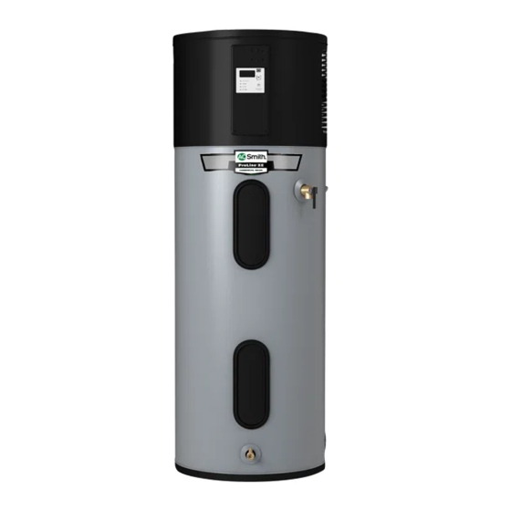
- Page 2 COMPLETED INSTALLATION (TYPICAL) TYPICAL INSTALLATION FOR 208V/240V Air Filter Condensate Drain Access Cover Connectivity Port User Interface Module (UIM) Temperature and Shut-off Valve Union* Pressure Relief Valve (Hot) Upper Element and ECO (Outlet) Primary Condensate Drain (3/4” PVC) Discharge Pipe (Do Not Cap or Plug) Thermal Expansion Tank Lower Element...
-
Page 3: Important Safety Information
IMPORTANT SAFETY INFORMATION Read and follow all safety messages and instructions in Important information to keep this manual. Fill out this section and keep this manual in the pocket of the water This is the safety alert symbol. It is used to alert you to heater for reference. - Page 4 IMPORTANT SAFETY INFORMATION RISKS DURING OPERATION o reduce the risk of property For information about changing the damage, serious injury or death, factory thermostat setting(s), refer to Scalding Risk read and follow the precautions below, the “Adjusting Temperature” section in This water heater all labels on the water heater, and this manual (“Step 12”...
- Page 5 IMPORTANT SAFETY INFORMATION According to a national standard • Keep the water heater from becom- Maintain the T&P Relief Valve properly. American Society of Sanitary Engineer- ing wet. Immediately shut the water Follow the maintenance instructions ing (ASSE 1070) and most local plumbing heater off and have it inspected by a provided by the manufacturer of the codes, the water heater’s thermostat...
-
Page 6: Getting Started
GETTING STARTED Review all of the instructions • Teflon® tape or pipe joint com- pound approved for potable water before you begin work. Improper installation can • Tools to make the electrical connec- damage the water heater, your home tions (for example, screwdrivers, and other property, and can present wire strippers) risks of serious injury or death. -
Page 7: Installation
INSTALLATION Follow these steps for proper HOW: Connect the Thermal Expansion installation: Tank (available at your local plumbing supplier) to the cold water supply line Step 1: near the water heater. The expansion ✓ tank contains a bladder and an air Verify that your charge. - Page 8 INSTALLATION BACKGROUND: Water expands when WARNING! Even if the water heater thermostat is set to a relatively low heated, and the increased volume temperature, hot water can scald. of water must have a place to go, or Install Thermostatic Mixing Valves thermal expansion will cause large to reduce the risk of scalding (page increases in water pressure (despite...
- Page 9 INSTALLATION The location has adequate Avoid locations such as upper The site location must be space (clearances) for period- floors, or where a leak might free from any corrosive ic servicing. For optimal water damage the structure or elements in the atmosphere heater efficiency, the unit must have furnishings.
- Page 10 INSTALLATION Step 3: WARNING! Be sure the water runs When the tank is empty, cool before draining the tank to re- disconnect the Temperature & Removing the old water duce the risk of scalding. Pressure (T&P) Relief Valve discharge pipe. You may be able to heater Connect a garden hose to reuse the discharge pipe, but do not...
- Page 11 INSTALLATION Step 4: • There is adequate access and space Locate the wiring behind the around the water heater for future condensate drain access cover maintenance. A minimum clearance Installing the new by removing the 4 screws of 6 in. must be maintained from attaching the cover to the unit.
- Page 12 INSTALLATION WARNING! To avoid serious injury • Use appropriate fittings and Condensate Drain or death from explosion, install a T&P primer to cement the condensate Access Cover Relief Valve according to the following Primary Drain drains to the heat pump drain Connection instructions: pan.
- Page 13 INSTALLATION Step 9: Terminate the discharge pipe Install a Thermostatic Mixing a maximum of 12 in/300 mm Valve. Consult the valve Connect the water above a floor drain, sump or manufacturer’s instructions or supply other safe location. Do not drain the a qualified person.
- Page 14 INSTALLATION IF YOU HAVE COPPER PIPES: NOTICE: This water heater model con- tains an outlet connection (J-tube) that If your home has copper water pipes, has an orientation mark that must line up with arrow (in a 12 o’clock position). you can solder the water pipe connec- tions or use compression fittings which Connect the hot water supply...
- Page 15 INSTALLATION Open a hot water faucet and This water heater requires a allow the water to run until it 240/208 VAC single phase 30 flows with a full stream. amp power supply, at 60Hz. Check the water heater’s data plate Let the water run full stream (see figure 23 on page 15) and ensure for three full minutes.
- Page 16 INSTALLATION Operation For detailed descriptions of all opera- set points until the desired tempera- ture is displayed. The temperature tional modes see “Operating Mode The water heater is now ready for setting will blink on the display; Descriptions” page 17. normal operation.
- Page 17 INSTALLATION Post Installation Review Water Temperature Ad- (upper or lower) and the heat pump simultaneously to help improve justment Understand how to use the recovery. This transition is seamless User Interface Module to set and will go unnoticed. The water temperature can be the various modes and adjusted from 95°F / 35°C to 150°F / functions.
- Page 18 INSTALLATION Electric Mode - NOTE: When Vacation Mode is formance. During the defrosting selected, the vacation timer will be dis- period, the user interface module The water heater functions as a played. Press the Up and Down button will display “ICE” as an indication. conventional electric unit, relying on to modify the timer to desired number only the elements for heat.
- Page 19 INSTALLATION Temperature Unit Indication Light Temperature Up (Increase) Button °F °C Display Segment DAYS Temperature Down (Decrease) Button Mode/Enter Operational Mode Button Indication Light Vacation Time Indication Figure 26 - User Interface Module (UIM) Display Optional Heat Trap Piping Vacuum Relief Valve (when required by local code) *Union Cold Water...
-
Page 20: Diagnostic Codes
DIAGNOSTIC CODES WARNING! Electric Shock Hazard; Disconnect power before servicing. Do not remove the plactic guard from over wiring. Do not touch electrical wiring. Failure to do so can result in death or electrical shock. DISPLAY SHOWS INDICATES CORRECTIVE ACTION - -- --- (series of dashes) Unit is doing a system diagnostic. - Page 21 DIAGNOSTIC CODES WARNING! Electric Shock Hazard; Disconnect power before servicing. Do not remove the plactic guard from over wiring. Do not touch electrical wiring. Failure to do so can result in death or electrical shock. Condensate management 1. Ensure unit is installed level. 2.
-
Page 22: Troubleshooting
TROUBLESHOOTING WARNING! Working near an energized • Locate the electrical junction box Check the top two screws of the on the side of the water heater and circuit can result in severe injury or death ECO using a non-contact circuit remove the cover. - Page 23 TROUBLESHOOTING Check/Reset Energy Cut Off • Replace the insulation and the upper Debris. In rare cases, debris can stick in- access panel. ECO Button. side the T&P Relief Valve preventing the valve from seating fully. In that case, the • Turn the power back on to the water T&P Relief Valve discharge pipe will drip.
-
Page 24: Water Heater Sounds
TROUBLESHOOTING Water Heater Sounds Low Water Pressure • Lower heating element not function- ing properly. During the normal operation of the Check both the cold and hot water at a • No power to the water heater (No water heater, sounds or noises may be sink to determine if the lower pressure lights on the unit are on and display heard. - Page 25 TROUBLESHOOTING User Interface Module (UIM) set too Lower heating element not working. low. If the water temperature at several If the lower heating element is not faucets is too cool, adjust the UIM ac- working, you will have some hot water cording to the instructions in Step 12 of but not as much as before.
-
Page 26: Maintenance
MAINTENANCE Routine Maintenance • Sediment may form large masses that Open the drain valve on the can prevent the tank from draining. water heater. Have a qualified person use a de-lim- Routine maintenance will help your ing agent suitable for potable water water heater last longer and work bet- to remove the sediment buildup. - Page 27 MAINTENANCE Element Anode Rod. The anode rod is a sac- • Garden hose to drain the tank rificial metal rod that helps reduce • Hand dishwashing soap to lubricate corrosion and premature failure (leaks) WARNING! Working on an ener- the gasket in the tank.
- Page 28 MAINTENANCE Remove the bad element the element. Inspect the gasket for Open a hot water faucet and let the hot water run until it is using an element wrench. damage. If the gasket is damaged, cool. replace the gasket and re-install the Make sure the new element is element.
- Page 29 MAINTENANCE T&P Relief Valve Main- • A replacement ECO (available by Mark the wires with tape so calling the number in the repair you’ll know how to put them tenance parts list located on page 31). A back on. business card to check the gap Read and follow the operating and between the ECO and tank.
-
Page 30: Condensate Drain
MAINTENANCE • At least every five years, have a NOTE: The water heater may conduct a qualified person inspect the T&P system diagnostic prior to operation. Relief Valve and discharge pipe. Condensate Drain Damage caused by corrosive water conditions, mineral deposits, or Maintenance other problems can only be deter- mined when a qualified person... -
Page 31: Repair Parts Illustration
REPAIR PARTS ILLUSTRATION REPAIR PARTS LIST PARTS DESCRIPTION PART NUMBER ITEM Personnel Protector 9003900005 Element (4500 Watts) 9000092015 Energy Cut-Off (ECO) Switch 9008167015 Temperature & Pressure Relief Valve 9000728015 (T&P) J-Tube (at hot water outlet) 11.25” for 9008848005 50 gallon J-Tube (at hot water outlet) 14.25”... - Page 32 Tef on® is a registered trademark of Chemours A.O. Smith Water Heaters 599, Hill Street West Fergus, ON Canada N1M 2X1 Should you have any questions, please visit us online at www.hotwater.ca; or email us at techsupport@hotwater.com; or Call our tech support line at 1 888 GSW TECH (479 8324)
Need help?
Do you have a question about the ProLine XE and is the answer not in the manual?
Questions and answers
WHAT DOES FLASHING BLUE LIGHT INDICATE
BLUE LIGHT ?