Table of Contents
Advertisement
Quick Links
Advertisement
Table of Contents

Related Manuals for Edimax AR-6024


Summary of Contents for Edimax AR-6024
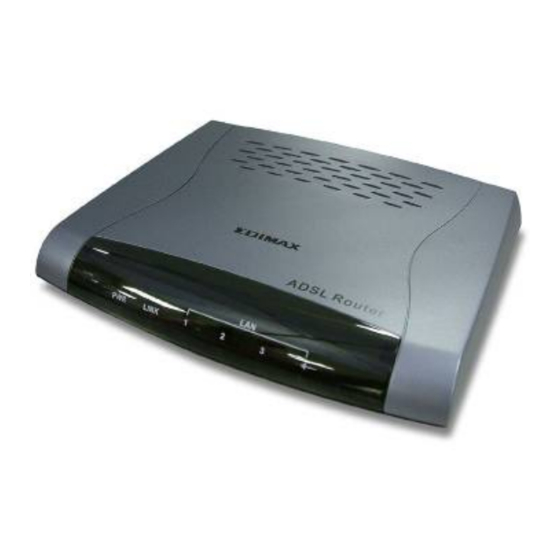
- Page 1 ADSL Broadband Router AR-6024 User’s Manual...
-
Page 2: Table Of Contents
Table of Contents Specification... 2 Package Contents ... 5 Hardware Connecting... 6 LED Indicators... 7 General Setting ... 8 One Page Setup--------------------------------------------------------------------------------- 12 Status ---------------------------------------------------------------------------------------------- 14 Router ... 14 ADSL ... 16 PPP... 17 Advanced Setting ... 22 ADMINISTRATION ----------------------------------------------------------------------------- 23 WAN... -
Page 3: Specification
Specification 4-Port Ethernet ADSL Router Features ADSL Compliance ANSI T1.413 i2 ITU G.992.1 (G.dmt) Annex A, B ITU G.992.2 (G.lite) Maximum downstream rate of 8Mbps Maximum upstream rate of 1Mbps Dying Gasp (optional) ATM Protocols and Encapsulations PPP over ATM (RFC 2364) PPP over Ethernet (RFC 2516) Bridged/Routed Ethernet over ATM (RFC 1483) Classical IP over ATM (RFC 1577) - Page 4 DHCP server/client/relay agent PPP auto reconnect and configurable timeouts PPP auto reconnect on WAN access PPP Auto, PAP, and CHAP 128 character support for PPPx username/passwords DNS proxy NAT, NAPT & Dynamic NAPT ALG support (FTP, SMTP/POP3, ICMP, NNTP, RTSP, IRC, CuSeeMe, Telnet, Messenger, EPIC games, id games, Sierra studios games) Wild Card DMZ Virtual server (Port mapping)
-
Page 5: Application Diagram
Hardware LAN: 4-Port 10/100Base-T (RJ-45) ADSL: One Port (RJ-11) Power: 9VAC 800mA LED indicators: Power, Ready (Status), ADSL, LAN*4 Reset button Certification: FCC Part 15/Part 68, CE, LVD Application Diagram Internet... -
Page 6: Package Contents
Package Contents ADSL Router CD-ROM containing Manual Ethernet Cable (CAT5 UTP Straight-Through) ADSL Cable (Standard telephone cable) USB Cable (Optional) Power Adapter Quick Installation Guide hardcopy... -
Page 7: Hardware Connecting
Hardware Connecting 4 Port Ethernet ADSL Router Splitter (optional and changes depending on country specification) RJ-45 Ethernet port connect Ethernet cable here RJ-11 ADSL port connect ADSL cable here Factory Reset Power Adapter (9VAC/800mA) Power cord connect here... -
Page 8: Led Indicators
LED Indicators Label Meaning Power WAN Link LAN 1/ LAN 2/ LAN Link LAN 3/ LAN 4 4 Port Ethernet ADSL Router Status Indicates Power is on Power is off Flashing Link being attempted by router. Link established No link Flashes when data is being sent or Flashing received on the LAN connection. -
Page 9: General Setting
General Setting You can use the RJ 45 cable or the USB cable connect to the ADSL Router. Please see the connecting procedures as below: Move your cursor as following sequence Start \ Settings \ Control Panel and click Control Panel. Then double-click on the Network Connections In the LAN or High-Speed Internet window, right-click on icon corresponding to your network interface card (NIC) and select Properties.(This icon may be labeled Local Area Connection). - Page 10 Highlight Internet Protocol (TCP/IP) under “This connection uses the following items.” by click on it once. Click on the Properties button. Select Obtain an IP address automatically: by clicking once in the circle. Click OK button to confirm and save your changes, and the close the Control Panel.
- Page 11 Launch your PC web browser and enter the URL: 10.0.0.2 In the User name/Password prompt, please type in admin/epicrouter as default.
- Page 12 Now you can start browsing the web through the ADSL device.
-
Page 13: One Page Setup
One Page Setup When working with wide area connections, the first thing you must do is to have the handle of the connection. Once you have the handle for a Connection you must define the PVC and protocol settings for it. LAN IP Address &... - Page 14 Password: Enter the password provided by your ISP. Disconnect Timeout: Disconnect Timeout means the router will disconnect after being idle for a preset amount of time. WAN Type: Select type from the list. VC Settings VPI: If instructed to change this, type in the VPI value for the initial connection (using PVC 0).
-
Page 15: Status
Status Router The Home page shows the Firmware Version and WAN and LAN interface status. Firmware Version: This field displays the Firmware Version number. WAN: These fields display the IP Address, Subnet Mask, MAC Address for WAN interface. - Page 16 LAN: These fields display the IP Address, Subnet Mask, MAC Address for LAN interface. Number of Ethernet devices connected to the DHCP server: This field displays the number of DHCP clients connected to the ADSL Router. It also shows the IP address and MAC address of the attached DHCP clients.
-
Page 17: Adsl
ADSL The ADSL Status page shows the ADSL physical layer status. Showtime Firmware Version: This field displays the ADSL data pump firmware version number. Line State: This field displays the ADSL connection process and status. Modulation: This field displays the ADSL modulation status for G.dmt or T1.413. Annex Mode: This field displays the ADSL Annex modes for Annex A or Annex B. -
Page 18: Ppp
The PPP Status page shows the status of PPP for each PPP interface. See PPP. These fields display the following information on each PPP interface: Connection Name (user defined) Interface (PVC) Mode (PPPoE or PPPoA) Status (Connected or Not Connected) Packets Sent Packets Received Bytes Sent... - Page 19 WAN Configuration: The WAN configuration page allows the user to set the configuration WAN/ADSL ports. Per VC Settings Virtual Circuit: Selection Enable or Disable. VPI: If instructed to change this, type in the VPI value for the initial connection (using PVC 0).
- Page 20 Bandwidth: Bandwidth setting takes effect only when the CBR is selected. The maximum available bandwidth is from the upstream data rate of ADSL status page. ENCAPSULATION: Selection follow as Table-1 Configuration BRIDGE: Enabling bridge mode will place the unit into Transparent bridge mode (like a Ethernet ADSL modem) to use this mode you should also set your WAN type to a Bridging option (e.g RFC1482 Bridge using LLC).
- Page 21 Table-1 Configuration Bridge Mode Configuration IP address Subnet Mask WAN Type 1483 Bridged IP LLC, 1483 Bridged IP VC-Mux Bridge Enabled PPP Service PPP User name Password DHCP Client Unchecked enable Table-2 Rx Entity Packet Class ADSL IGMP query IGMP report IGMP leave General Multicast IP Ethernet...
- Page 22 PPP: The current release supports multiple PPP sessions per PVC. The PPP configuration in the WAN configuration page is for the first PPP session for each PVC. The predefined PPP Account Name (Account ID) is “Simple PPP Account 0” for PVC0 and predefined PPP Connection Name is “Simple PPP Session 0” for PVC0.
- Page 23 please leave it blank. Note: Click the Submit button to save the settings in temporary memory. If you make changes the configurations.
-
Page 24: Advanced Setting
Advanced Setting ADMINISTRATION The links under the ADMINISTRATION column are associated to the pages that represent the configurations of system and interfaces. Note: When the configurations are changed, please click the Save Setting and Reboot button. The WAN configuration page allows the user to set the configuration for WAN/ADSL ports. - Page 25 Per VC Settings Virtual Circuit: Selection Enable or Disable. VPI: If instructed to change this, type in the VPI value for the initial connection (using PVC 0). Default = 0. VCI: If instructed to change this, type in the VCI value for the initial connection (using PVC 0).
- Page 26 End-user multicast application device send IGMP report while receiving IGMP query or being activated by user, the ADSL modem should be responsible to proxy (that is, change source IP to ADSL modem’s WAN IP) the IGMP report to ADSL WAN side, include all PVCs. The same case is for IGMP leave packet. Not necessary to relay multicast routing between two ADSL PVCs or two interfaces in LAN side.
- Page 27 Table-1 Configuration Bridge Mode Configuration IP address Subnet Mask WAN Type 1483 Bridged IP LLC, 1483 Bridged IP VC-Mux Bridge Enabled PPP Service PPP User name Password DHCP Client Unchecked enable Table-2 Rx Entity Packet Class ADSL IGMP query IGMP report IGMP leave General Multicast IP Ethernet...
- Page 28 PPP: The current release supports multiple PPP sessions per PVC. The PPP configuration in the WAN configuration page is for the first PPP session for each PVC. The predefined PPP Account Name (Account ID) is “Simple PPP Account 0” for PVC0 and predefined PPP Connection Name is “Simple PPP Session 0” for PVC0.
- Page 29 please leave it blank. Note: Click the Submit button to save the settings in temporary memory. If you make changes the configurations.
-
Page 30: Lan
The LAN configuration page allows you to set the configuration for the LAN port. LAN IP Address & Subnet Mask: The default is 10.0.0.2 and 255.0.0.0 you can change it to another private IP address, such as 211.22.10.191 and 255.255.255.0. For most configurations it is recommended to leave it as default. DHCP Server: System Allocated. - Page 31 DHCP Gateway Selection: The default setting for the DHCP Gateway Selection is “Automatic”. The user can select the “User Defined” to specify “User Defined Gateway Address”. The DHCP server will issue the “ User Defined Gateway Address” to the LAN DHCP client. Lease time: The lease time is the amount of time of a network user will be allowed to connect with DHCP server.
-
Page 32: Dns
The DNS Configuration page allows you to set the configuration of DNS proxy. Disable DNS Proxy: The LAN port does not process the DNS query message. For the DHCP requests from local PCs, the DHCP server will set the user-configured preferred DNS sever or alternate DNS server whichever is available as the DNS server. -
Page 33: Nat
The NAT Configuration page allows users to set the configuration for the Network Address Translation. The default setting is Dynamic NAPT. It provides dynamic Network Address Translation capability between LAN and multiple WAN connections, and the LAN traffic is routed to appropriate WAN connections based on the destination IP address and Route Table. - Page 34 Number of NAT Configurations: This field displays the total number of NAT Sessions is entered. Available Sessions Status will be displayed at the end of this page to show all the Session Name with its WAN Interface. Interface: This field allows the user to choose specific WAN Interface (PVC or PPP Session) for NAT Session.
-
Page 35: Port Forwarding
Port Forwarding The Port Forwarding page allows the user define a port forwarding rule without using the firewall policy database definitions and apply it to the connection. Public Port: This field allows the user to enter the port number of Public Network. Private Port: This field allows the user to enter the port number of the Private Network. -
Page 36: Adsl Configuration
ADSL Configuration The ADSL Configuration page allows users to set the configuration for ADSL protocols. Trellis: This field allows the user to enable or disable the Trellis Code. By default, it is always enabled. Handshake Protocol: This field allows the user to select the ADSL handshake protocol. -
Page 37: Rip Configuration
RIP Configuration The RIP System Wide Configuration page allows the user to set the configuration for each Interface (PVCs, PPP Sessions, USB and LAN). Interface: This field allows the user to choose the Interface (PVCs, PPP Sessions, USB and LAN), for the RIP to be configured. Enable: This field allows the user to Enable (Yes) or Disable (No) the Specified interface for RIP. -
Page 38: Firewall
Firewall The Firewall page allows users to configure various database/firewall options and Inbound/Outbound policies for controlling Inbound/Outbound traffic. Firewall: This field allows the user to Disabled or Enabled Firewall. Note: Click the Submit button to save the settings in temporary memory. If you make changes the configurations. - Page 39 Ping of Death checking: Ping of Death is a type of DoS attack that uses a malformed ICMP data packet that contains unusually large amounts of data that causes TCP/IP to crash or behave irregularly. Enabling this will allow the firewall to filter out packets containing Ping of Death properties.
- Page 40 containing the threat. Source Routing checking: Source routing gives the sender of a packet the ability to determine the exact route that an IP packet takes to get to the destination. However, source routing can be used for malicious reasons. Using a source routed packet, the sender could find out important information about nodes in a network, making it easy to exploit any weakness.
- Page 41 Hacker Log This page allows you to configure which Protection Policy (see previous section) violations to log for admin viewing. Alert Log: Enable/ Disable for SYN Flooding, Ping of Death, IP Spoofing, and WinNuke (all of these are explained in the previous section). Enable to log violations of individual policies.
-
Page 42: Service Filtering
Service Filtering Service Filtering allows you to disable service request from certain sources. Note: Click the Submit button to save the settings in temporary memory. If you make changes the configurations. - Page 43 Firewall Databases: IP Group The IP Group lets you specify IP Addresses (Single or Range) and Subnet Masks and assign them to a group name for easy use when configuring inbound and out bound policies for the firewall. IP Entry Name: This is the name you assign to the group of IP addresses and subnet masks.
- Page 44 Service Group The Service Group lets you specify a Port and assign it to a group name for easy use when configuring inbound and outbound policies for the firewall. Service Entry Name: This is the name you assign to the group containing the port number.
- Page 45 Time Window The Time Window lets you specify certain time periods and assign them to a group name for easy use when configuring inbound and outbound policies for the firewall. Time Window Name: This is the name you assign to the group that is given the time designation.
- Page 46 Inbound/ Outbound Policies: Inbound Policy The Inbound Policy allows you to filter inbound (from the WAN into the user side LAN) packets based on a set of rules. This enables you to deny access from different sources and thus increase security. Src IP: This specifies the Source IP for the Inbound Policy.
- Page 47 affected by the policy. See Src IP above for configuration detail. Src Port: This specifies the Source Port for the Inbound Policy. This is the external (WAN side, outside of the firewall) port(s) that will be affected by the policy. In this field, there are two port entry fields and a dropdown menu.
- Page 48 Outbound Policy The Outbound Policy allows you to filter outbound (from the user side LAN to the WAN) packets based on a set of rules. This enables you to deny access to different sources and thus increase security. Src IP: This specifies the Source IP for the Outbound Policy. This is the internal (LAN side, behind the firewall) IP address or addresses and Subnet Mask(s) that will be affected by the policy.
- Page 49 Src Port: This specifies the Source Port for the Outbound Policy. This is the internal (LAN side, behind firewall) port(s) that will be affected by the policy. In this field, there are two port entry fields and a dropdown menu. The dropdown menu has four options: Any Port: Selecting this will cause all Ports to be affected by the policy.
-
Page 50: Diagnostic Test
Diagnostic Test The Diagnostic Test page shows the test results for the physical layer and protocol layer for both LAN and WAN sides. Testing Ethernet LAN Connection: This test checks the Ethernet LAN interface connection. Testing ADSL Synchronization: This test checks the ADSL showtime. If this test returns FAIL, all other tests will be skipped. - Page 51 Ping Primary DNS: This test checks the primary DNS can be reached through pin request. Query DNS for www.conexant.com: This test checks the host name can be resolved to IP address though domain name servers. Ping www.conexant.com: This test checks the specified host can be reached through pin request.
-
Page 52: Router Table
Router Table The Router Table page displays routing table and allows the user to manually enter the routing entry. The routing table will display the routing status of Destination, Netmask, Gateway and Interface. The interface br0 means the USB interface; Io0 means the loopback interface and ppp1 means the PPP interface. -
Page 53: Mac Filtering
MAC Filtering The MAC Filtering configuration page allows the user to set the configuration of IP filtering. Enable and Disable MAC filtering by selecting the “Yes” or “No” radio buttons. Source MAC: When the bridge filtering is enabled, enter the Source Mac address, Select Block and click Add. -
Page 54: Security
Security The links under Security are only to be accessed and configured, when it is login with administrator login name and password. Admin Password The Admin Password Configuration page allows the user to set the password for administrator. User Name: admin Password (default): epicrouter Note: Click the Submit button to save the settings in temporary memory. -
Page 55: User Password
User Password The User Password Configuration page allows the Admin user to set the password for the general user. When logged in as a general user you can view the basic status. User Name: user Password (default): password Note: Click the Submit button to save the settings in temporary memory. If you make changes the configurations. -
Page 56: Misc Configuration
Misc Configuration The Miscellaneous Configuration allows the user to set all the miscellaneous configurations. HTTP server access: This field allows the user to configure the Web pages can be accessed from. ALL: When this field is checked, it allows both WAN and LAN access to the Web pages. - Page 57 FTP server: This field allows the user to Enable or Disable the FTP connection. If you want FTP access from the WAN side you must ensure there are no port forwards for port 21. TFTP server: This field allows the user to Enable or Disable the TFTP connection. DMZ: A DMZ (De-Militarized Zone) is added between a protected network and an external network, in order to provide an additional layer of security.
-
Page 58: System Log
System Log The System Log page shows the events triggered by the system. To clear the System Log simply click on the Clear Log button. Note: Click the Submit button to save the settings in temporary memory. If you make changes the configurations. -
Page 59: Code Update
Code Update The code Update page allows the user to upload new firmware to the ADSL Router. To upload new firmware: 1. Download the latest firmware image from the website. 2. Save the file to your Desktop or other location. 3. -
Page 60: Status
Status Router The Home page shows the Firmware Version and WAN and LAN interface status. Firmware Version: This field displays the Firmware Version number. WAN: These fields display the IP Address, Subnet Mask, MAC Address for WAN interface. LAN: These fields display the IP Address, Subnet Mask, MAC Address for LAN interface. - Page 61 number of DHCP clients connected to the ADSL Wireless Router. It also shows the IP address and MAC address of the attached DHCP clients.
-
Page 62: Adsl
ADSL The ADSL Status page shows the ADSL physical layer status. Showtime Firmware Version: This field displays the ADSL data pump firmware version number. Line State: This field displays the ADSL connection process and status. Modulation: This field displays the ADSL modulation status for G.dmt or T1.413. Annex Mode: This field displays the ADSL Annex modes for Annex A or Annex B. -
Page 63: Wan Status
WAN Status The WAN Status page shows the information and status of WAN PVCs. WAN: These fields display the IP Address, Subnet Mask and MAC Address for the WAN (ADSL) interface. Use the Virtual Circuit selection to selection different PVC for status display. -
Page 64: Atm Status
ATM Status The ATM Status page shows all the statistics information of ATM cells. Reset Counters: This button allows user to reset the ATM Status counter. -
Page 65: Tcp Connections
TCP connections The TCP Status page shows the statistics for all TCP connections. -
Page 66: Learned Mac Table
Learned MAC Table The Learned MAC Table page shows the current learned Bridge MAC table. Aging Timeout: This field allows the user to enter the update period for the MAC table. Note: Click the Submit button to save the settings in temporary memory. If you make changes the configurations. -
Page 67: Ppp Status
PPP Status The PPP Status page shows the status of PPP for each PPP interface. See PPP. These fields display the following information on each PPP interface: Connection Name (user defined) Interface (PVC) Mode (PPPoE or PPPoA) Status (Connected or Not Connected) Packets Sent Packets Received Bytes Sent... -
Page 68: Save Settings/Reboot
Save Settings/Reboot The Save Settings/Reboot page allows users to save the new configuration to the flash and reboot the system. When the configurations are changed via the Web pages, the settings need to be saved into the flash, so it is necessary to go to this Save Settings/Reboot page to save and reboot the system for the changes to be taken effect. -
Page 69: Appendix
Appendix Country Australia Belgium Canada Danmark Deutschland All Internet providers Telus Cybercity Tiscali 1 & 1 Internet DSL AOL DSL Arcor DSL Freenet DSL Fireline networks GMX Internet Hansenet Netcologne Schlund Snafu ADSL VPI:8 VCI:35 VPI:0 VCI:33 VPI:0 VCI:35 VPI:8 VCI:35 VPI:8 VCI:35... - Page 70 Country France ISRAEL Italian Netherlands New Zealand Portugal Spanish Tiscali T-online Anderer Anbieter Wannadoo Tiscali KPN PPPoE LLC Telecom Italia Rest oil presente KPN PPPoA VC-MuX BBeyond Bridge LLC BBeyond PPPoA VC-MuX New Zealand Telecom Todos os apresentador Albura Colt Teeccom Earth VPI:1 VCI:32...
- Page 71 Country Spanish Suomi Switserland Sverige Eresmas Jazztel Ola Internet Retevision Terra Tiscali Telefornica Telepac Uni2 Ya.com Wanadoo Island ssimi Landssimi Vortex Alle anbieter Skanova VPI:8 VCI:35 VPI:8 VCI:35 VPI:8 VCI:35 VPI:0 VCI:35 VPI:8 VCI:32 VPI:1 VCI:32 VPI:8 VCI:32 VPI:8 VCI:35 VPI:1 VCI:33 VPI:8...
- Page 72 Country Taiwan United Arab Emirates United Kingdom Hinet Seednet Etisalat Classical IP Single User Etisalat Classical IP for Business British Telecom VPI:0 VCI:33 VPI:0 VCI:33 VPI:8 VCI:35 VPI:8 VCI:35 VPI:0 VCI:38...
Need help?
Do you have a question about the AR-6024 and is the answer not in the manual?
Questions and answers