Table of Contents
Advertisement
Available languages
Available languages
Operator's
Manual
CRRFTSMRN
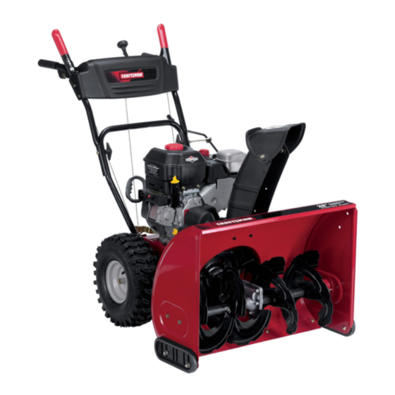
28" SNOW THROWER
Model No. 247.88690
CAUTION:
Before
using
this product,
read this
manual
and follow
all
safety
rules
and operating
instructions.
o SAFETY
ASSEMBLY
OPERATION
MAINTENANCE
PARTS LIST
o ESPANOL
Sears, Roebuck and Co., Hoffman
Estates,
IL 60179, U.S.A.
Visit our website:
www.craftsman.com
FORMNO.769-03973
2/4/2009
Advertisement
Table of Contents

Subscribe to Our Youtube Channel
Related Manuals for Craftsman 88690 - 250cc 28" Path Two Stage Snow Thrower


Summary of Contents for Craftsman 88690 - 250cc 28" Path Two Stage Snow Thrower
- Page 1 Model No. 247.88690 o SAFETY ASSEMBLY OPERATION MAINTENANCE PARTS LIST CAUTION: Before using o ESPANOL this product, read this manual and follow safety rules and operating instructions. Sears, Roebuck and Co., Hoffman Estates, IL 60179, U.S.A. Visit our website: www.craftsman.com FORMNO.769-03973 2/4/2009...
- Page 2 Operation ......Pages 12-15 Espa_ol ......Page43 Service &Maintenance ....Pages 16-23 CRAFTSMAN LiMiTED WARRANTY Two Years on Snow Thrower Whenoperatedand maintained accordingto all suppliedinstructions, ifthis snowthrowerfailsdue to a defectinmaterialor workmanship within two yearsfrom the dateor purchase,call 1-800-4-MY-HOME® to arrangefor free repair.
-
Page 3: California Proposition
This machinewas builtto be operatedaccordingto the safe opera- This symbolpointsout importantsafetyinstructionswhich,if not tion practicesin this manual.As with any type of powerequipment, followed,couldendangerthepersonalsafetyand/orpropertyof carelessness or error on the partof the operatorcan result in serious yourselfand others. Readand followall instructionsin this manual injury.This machineis capableof amputatingfingers,hands,toes beforeattemptingto operatethis machine.Failureto complywith and feet and throwingdebris. -
Page 4: Operation
Safe Handling of Gasoline • Exerciseextremecautionwhenoperatingon or crossinggravel surfaces.Stay alertfor hidden hazardsor traffic. Toavoidpersonalinjuryor propertydamageuseextremecare in handlinggasoline.Gasolineis extremelyflammableand the vaporsare • Exercisecautionwhenchangingdirectionand whileoperatingon explosive.Seriouspersonalinjurycan occurwhengasolineis spilled slopes. on yourselfor yourclotheswhichcan ignite.Washyour skin and • Planyoursnow-throwing patternto avoiddischargetowards changeclothesimmediately. windows,walls,cars etc. Thus,avoidingpossibleproperty •... -
Page 5: Maintenance
MAINTENANCE & STORAGE DO NOT MODIFY ENGINE • Nevertamperwith safetydevices.Checktheirproperoperation Toavoidseriousinjuryor death,do not modifyengine in any way. regularly.Referto the maintenance and adjustmentsectionsof Tampering with the governorsettingcanlead to a runawayengineand this manual. cause it to operateat unsafespeeds.Nevertamperwithfactory setting of engine governor. •... -
Page 6: Safety Symbols
SAFETY SYMBOLS This pagedepictsand describessafetysymbolsthat mayappear on this product. Read,understand,and followall instructionson the machine beforeattemptingto assembleand operate. READ THE OPERATOR'S MANUAL(S) Read, understand, and follow all instructions in the manual(s) before attempting to assemble operate WARNING-- ROTATING BLADES Keep hands out of inlet and discharge openings while machine is running. - Page 7 1.KEEPAWAY FROMROTATING iMPELLER AND AUGER, C ONTACT WiTHiMPELLER OR AUGER CANAMPUTATE HANDS ANDFEET. 2. USECLEAN-OUT TOOL TOUNCLOG DISCHARGE C HUTE. 3.DISENGAGE C LUTCHLEVERS, S TOPENGINE, AND REMAINBEHINDHANDLESUNTIL ALL MOVING PARTSHAVE STOPPEDBEFORE UNCLOGGING OR SERViCiNG MACHINE. TO AVOIDTHROWN OBJECTSiNJURiES, NEVER DIRECT DISCHARGE A TBYSTANDERS. USEEXTRACAUTION WHEN OPERATING O N GRAVEL SURFACES.
-
Page 8: Removing From Carton
NOTE:References to rightor left sideof the snowthrowerare determined from behindthe unit in the operatingposition(standing directlybehindthe snow thrower,facingthe handlepanel). REMOVING FROM CARTON Cut the cornersof thecarton and lay the sidesflat on the ground. Removeand discard all packinginserts. Movethe snowthrowerout of thecarton. Makecertainthe carton has beencompletelyemptiedbefore discardingit. - Page 9 Positionthechute assemblyoverthe base.See Figure3. Closethe flangekeepersto securethechute assemblyto the chute base.See Figure4. The flangekeeperswill click intoplace whenproperlysecure. NOTE:If the flangekeeperswill noteasily clickinto place,usethe palmof yourhand to applyswift,firm pressureto the backof each. Removetheflat washerand hairpinclip from the end of the chutedirectionalcontrol. Insertthe end of the chutedirectionalcontrolinto the lower bracketand securewith the flat washerand hairpinclipjust removed.See Figure5.
- Page 10 SET-UP Chute Clean-Out Tool A chute clean-out tool is fastenedto the top of the augerhousing with a mountingclip. See Figure6. The tool is designedto cleara chuteassemblyof ice and snow.This item is fastenedwith a cabletie at the factory.Cut thecable tie beforeoperatingthe snowthrower. ChuteClean-outTool loft _1 .allmovingpartshave...
- Page 11 Chute Assembly Thedistancesnowis throwncan be adjustedby changingthe angle of the chuteassembly.Todo so: Stopthe engineby removingthe ignitionkeyand loosenthe plasticwingknobfoundon the left sideof the chuteassembly. Pivotthe chute upwardor downwardbeforeretightening thewing knob.See Figure8. Auger Control Priorto operatingyour snowthrower,carefullyreadand followall instructionsbelow. Performall adjustmentsto verifyyour snow throweris operatingsafelyand properly.
- Page 12 Auger Control Gas Cap ChuteAssembly Chute Directional Control Clean Out Tool Recoil Starter Handle Electric Start Button Augers Skid Shoe Outlet Figure10 iGNiTiON Nowthat youhaveset up yoursnowthrower,it'simportant to become acquainted with its controlsand features.Referto Figure10. The ignition keyisa safetydevice.It mustbe fully insertedin orderfor the engineto start.
-
Page 13: Recoil Starter
RECOIL STARTER HANDLE DRIVE CONTROL/AUGER CONTROL LOCK This handleis usedto manuallystartthe engine. ELECTRIC STARTER BUTTON Pressingthe electricstarterbuttonengagesthe engine'selectric starterwhenpluggedintoa 120Vpowersource, ELECTRIC STARTER OUTLET Requiresthe useof a three-prongoutdoorextensioncord(included) and a 120Vpowersource/walloutlet. PRIMER Depressingthe primerforcesfuel directlyintothe engine'scarburetor to aid in cold-weatherstarting, The drivecontrolis located on the righthandle.Squeezethe control grip againstthe handleto engagethe wheeldrive. -
Page 14: Clean-Out Tool
CLEAN-OUT TOOL Useextremecarewhen handlinggasoline.Gasolineis extremely flammableand thevaporsare explosive.Never fuelthe machine Neveruseyour handsto cleara cloggedchuteassembly.Shut indoorsor whilethe engine is hotor running.Extinguishcigarettes, off engineand remainbehind handlesuntilall movingparts have cigars,pipesand othersourcesof ignition. stoppedbeforeusingthe clean-outtool to clearthe chute assembly. Alwaysfill the fuel tank outdoorsand usea funnelor spoutto preventspilling. -
Page 15: To Engage Augers
Pushstarterbuttonto start engine. NOTE:NEVERrepositiontheshift lever(changespeedsor direction of travel)withoutfirst releasingthe drivecontrol and bringingthe snow throwerto a completestop.Doingsowill resultin premature wearto the snow thrower'sdrivesystem. To prolongstarterlife, useshort startingcycles(5 secondsmaximum then wait one minute). TO ENGAGE AUGERS Oncethe enginestarts,releasestarterbutton. Toengagethe augersand startthrowingsnow,squeezethe Allowtheengine to warmup severalminutes,adjustingchoke auger controlagainstthe left handle.Releaseto stop theaugers. -
Page 16: Engine Maintenance
MAINTENANCE SCHEDULE Before performing anytypeofmaintenance/service, disengage all Followthe maintenance schedulegiven below.This chart describes controls and stoptheengine. W aituntilall moving partshavecometo serviceguidelinesonly. Usethe ServiceLog columnto keeptrackof a completestop.Disconnect sparkplugwireandgrounditagainst t he completedmaintenance tasks.To locate the nearest Sears Service enginetoprevent u nintended starting. A lwayswearsafetyglasses during Centeror to scheduleservice,simplycontactSearsat 1-800-4-MY-HOME®. - Page 17 3. With engine OFF but s till w arm, remove oil d rain p lug a nd drain o il into anappropriate receptacle. See Figure 13. 0il FIll Used o ilisahazardous waste p roduct. Dispose ofused o ilproperly. IDonot d iscard with household waste.
-
Page 18: Shave Plate And Skid Shoes
Engine Speed Toavoidserious injury or death, DONOTmodifyenginein any way.Tampering with the governorsettingcan causethe engineand equipmentto operateat unsafespeeds.NEVERtamperwith factory settingof enginegovernor.Runningthe enginefasterthan the speed set at thefactory is dangerous. LUBRICATION Gear Shaft Thegear (hex)shaft shouldbe lubricatedat least oncea seasonor afterevery 25 hoursof operation. Topreventspillage,removeall fuel fromtank by runningengine until it stops. - Page 19 ADJUSTMENTS Shift Cable If thefull rangeof speeds(forwardand reverse)cannotbe achieved, referto the figureto the rightand adjustthe shift cableas follows: Placethe shiftleverin thefastest (F6) forwardspeedposition. Loosenthe hex nuton the shiftcable indexbracket.See Figure Pivotthe bracketdownwardto take up slack in the cable. Retightenthehex nut. Drive Control Whenthedrivecontrol is releasedand in thedisengaged"up"position, the cableshouldhavevery little slack.It shouldNOTbe tight.
-
Page 20: Belt Replacement
Auger Control "_ Referto the Assemblysectionfor instructions on adjustingtheauger controlcable. Skid Shoes Referto the Assemblysectionfor instructions on adjustingthe skid shoes. BELT REPLACEMENT Auger Belt To removeand replaceyoursnow thrower'sauger belt, proceedas follows: Topreventspillage,removeall fuel fromtank by runningengine until itstops. Removethe plasticbelt coveron the front of the engineby remov- ing the two self-tappingscrews.See Figure22. - Page 21 6. Remove the belt a sfollows. Refer toFigure 25. a. Loosen and remove the shoulder screw w hich a cts a sabelt keeper. b. Unhook the support bracket spring f rom the frame. 7. Remove the belt f rom around the auger pulley, and slip the belt between thesupport bracket and the auger pulley.
-
Page 22: Friction Wheel Removal
4, Carefully pivot the snow thrower upand forward so that i trests o n the auger housing. 5. Remove the frame c over from the underside ofthe snow thrower byremoving four s elf-tapping screws which s ecure it.Refer to Figure 24, 6. - Page 23 NOTE: Be careful not t odamage the threads onthe shaft, 7. Carefully position the hex shaft downward and tothe leftbefore carefully sliding the friction wheel assembly offthe shaft. See Figure 31. NOTE: Ifyou're r eplacing the friction wheel assembly asawhole, discard the worn p art and slide t he new part o nto the hex shaft.
-
Page 24: Preparing Snow Thrower
If the snowthrowerwillnot be usedfor30 daysor longer,or if it is the end of the snowseasonwhenthe last possibilityof snowis gone,the equipmentneedsto be storedproperly.Followstorageinstructionsbelowto ensuretop performance from the snowthrowerfor manymoreyears. PREPARING SNOW THROWER PREPARING ENGINE • Whenstoringthe snowthrowerin an unventilatedor metal stor- Forenginesstoredover30 days: age shed,careshouldbe taken to rustprooftheequipment.Using 1. - Page 25 Enginefails to start Chokecontrolnot in ON position Movechokecontrolto ONposition. Sparkplugwire disconnected Connectwireto spark plug. Faultysparkplug Clean,adjustgap,or replace. Fueltank emptyor stale fuel Filltank with clean, freshgasoline. Enginenotprimed. Primeengineas instructedin the OperationSection. Safetykeynot inserted. Insertkeyfully intothe switch. Enginerunserratically Enginerunningon CHOKE Movechokecontrolto OFFposition. Stalefuel Filltank with clean, freshgasoline.
- Page 26 Craftsman Snow Thrower Model 247.88690 i\:/,...
- Page 27 Craftsman Snow Thrower IViodel 247.88690 731-2635 Snow Removal T oolMount 684-04107-0637 SpiralAssembly,LH 684-04108-0637 684-04057A-0637 ImpellerAssembly,12"Dia. SpiralAssembly,RH 710-0347 HexScrew,3/8-16, 1.75,Gr5 731-04870 Spacer,1.25OD x .75 ID x 1.00 710-0451 Bolt,Carriage,5/16-18,.750Grl 736-0188 Washer,Flat, .76x 1.49x .06 710-04484 Screw, 5/16-18, 0 .750 741-0493A Bushing,Flange,.80 ID x .91OD...
- Page 28 Craftsman Snow Thrower Model 247.88690...
- Page 29 Craftsman Snow Thrower IViodel 247.88690 731-04869 Chute,FlangeKeeper 631-04133A HandleAssembly,ClutchLock, LH 746-04397 Cable,SpeedSelector 631-04134B HandleAssembly,ClutchLock, RH 749-04191A-0637 Handle,Upper,LH 684-04111B HandleAss'y, Engage,LH 747-0697 Eye Bolt,ChuteCrank 684-04112B HandleAss'y, Engage,RH 790-00313-0637 Shift Lever J 631-04131B _ ChuteAssembly(IncludesRef.# 27) 731-04912B Chute,Lower,5.0 Dia. 710-04326 Screw,#8-16x .50 710-0276 Bolt, Carriage,5/16-18,1.0...
- Page 30 Craftsman Snow Thrower Model 247.88690...
- Page 31 Craftsman Snow Thrower IViodel 247.88690 656-04025A DiscAssembly,FrictionWheel 634-04148A-0911 RH WheelAssembly,15x 5 x 6 684-04153 FrictionWheelAssembly,5.50D 731-04873 Spacer,1.25x .75x 3.0 738-04168 Axle, .75x 22" 684-04154-0637 SupportBracket,FrictionWheel 684-04156A ShiftAssembly,Rod 790-00218A-0637 Shift Bracket,Speed Selector 710-0809 Hex Screw,1/4-20,1.25,Gr5 J 710-0627 Hex Screw,5/16-24,.750,Gr5 710-0788 Screw,1/4-20,1.000 710-0191 Hex Screw,3/8-24, 1.25,Gr8...
- Page 32 Craftsman Engine Model 15C103-0661 For Snow Thrower Model 247.88690 110580PERATOR'sMANUAL] 48 SHORT BLOCK I 1329 REPLACEMENT ENGINE 1330 REPAIR MANUAL 307A _ 684 t)_' 742 % 177 ,:.C ,_ 287 G _ 24 0 524 __?) 358 ENGINE GASKET SET...
- Page 33 Craftsman Engine Model 15C103-0661 For Snow Thrower Model 247.88690 1026 .._:[: ..1029 F -_ _ 1034 1095 VALVE GASKET SET 51 _-ii_L_ 1022 1022 19o_?
- Page 34 Craftsman Engine Model 15C103=0661 For Snow Thrower Model 247.88690 663_% 1196A ¢_ ",\\ =:_ o _ _, o 1196 \ ..1251A 1070 (_ 1005 1252A _'> 1036 EMISSIONS LABEL 1252 65A_ _>...
- Page 35 Craftsman Engine IViodel 15C103-0661 For Snow Thrower IViodel 247.88690 562 '_'*_, 1o54 1347 13___._ _- lo4_ 4,. Y A _9 365_ 975_ 137 _I[_S ..'_I %.::::c 1009 276 q_ t ..276 _,_ _> 121 CARBURETOR OVERHAUL 104 _...
- Page 36 Craftsman Engine Model 15C103=0661 For Snow Thrower Model 247.88690 794188 CylinderAssembly 690937 Screw(RewindStarter)(SAE) 399269 Kit-Bushing/Seal ( MagnetoSide) 699228 Screw(RewindStarter)(Metric) 299819s• Seal-Oil (MagnetoSide) 691636 Screw(ThrottleValve) 690024 Shaft-Throttle 791720 Head-Cylinder 791716 .+ Gasket-Cylinder H ead 3981850 Kit-IdleSpeed 695745 Tube-Breather 6912420 Pin-FloatHinge 699485•...
- Page 37 Craftsman Engine IViodel 15C103-0661 For Snow Thrower IViodel 247.88690 699480 Screw(BlowerHousing) 793134 Cover-Control 604A 790473 Cover-Control 695710 Shield-Cylinder 699483 Screw(CylinderShield) (M4) 699335 Starter-Rewind 307A 699234 Screw(CylinderShield) (M5) 794614 Arrester-lntake 307B 790557 Screw(CylinderShield) (M4) 791972 Screw(Muffler) 793667 Motor-Starter 692576 Retainer-Governor Shaft...
- Page 38 Craftsman Engine Model 15C103-0661 For Snow Thrower Model 247.88690 794696 KeySet 694088 Gasket-Cylinder H eadPlate 794687 Shield-Carburetor 794701 Pipe-Oil 1005 692592 Fan-Flywheel 1009 790537 Screw(Starter Motor) 1022 691890o+ Gasket-Rocker C over 1023 499924 Cover-Rocker 1026 790287 Rod-Push 1029 691230 Arm-Rocker...
- Page 40 (Thispage applicablein the U.S.A.and Canadaonly.) Sears, Roebuck and Co., U.S.A. (Sears), the California Air Resources Board (CARD) and the United States Environmental Protection Agency (U.S. EPA) Emission Control System Warranty Statement (Owner's Defect Warranty Rights and Obligations) EMISSIONCONTROL WARRANTY COVERAGEISAPPLICABLE TO CERTI- YEAR 1997AND LATERENGINES WHICHARE PURCHASED AND USED FIEDENGINESPURCHASEDIN CALIFORNIAIN 1995ANDTHEREAF- ELSEWHERE IN THE UNITEDSTATES (ANDAFTERJANUARY1,2001 IN...
- Page 41 Look For Relevant Emissions Durability Period and Air index information On Your Engine Emissions Label Engines that are certified to meet the California Air Resources Board (CARB) Tier 2 Emission Standards must display information regarding the Emissions Durability Period and the Air Index. Sears, Roebuck and Co., U.S.A. makes this information available to the consumer on our emission labels.
- Page 42 Congratulations on makinga smartpurchase.YournewCraftsman@ Onceyou purchasethe Agreement,a simplephonecall is all that it productis designedand manufactured for yearsof dependableopera- takesfor youto scheduleservice.Youcan call anytimedayor night,or tion. But likeall products,it may requirerepairfrom time to time.That's schedulea serviceappointmentonline. whenhavinga RepairProtectionAgreementcansave youmoneyand The RepairProtectionAgreementis a risk-freepurchase.If youcancel aggravation.
- Page 43 ..Pagina 64 posterior GARANTiA LIMITADA CRAFTSMAN Dos Ahos en Lanzador de Nieve Cuandohechofuncionary mantenidosegQn todas lasinstrucciones suministradas, s i este lanzador d e nievefalla debidoa un defectoen mate- rial o habilidaddentrode dosa_osde la fechao compra,Ilame 1-800-4MYHOME hacerlosarreglospara reparaci6nlibre.
- Page 44 Esta rn_.quina rueconstruidapara seroperadade acuerdocon La presenciade este sirnboloindicaque setrata de instrucciones las reglasde seguridadcontenidasen este manual.AI igualque irnportantes de seguridadque se deben respetarpara evitar concualquiertipo de equipo rnotorizado, u n descuidoo error por poneren peligrosu seguridadpersonaly/o materialy la de otras partedel operadorpuedeproducirlesionesgraves.Estarn_.quina personas.Lea y sigatodas lasinstruccionesde este manualantes es capazde arnputarrnanosy piesy de arrojarobjetoscon gran...
- Page 45 Manejo seguro de la gasolina Nuncaopere la m_.quina si falta un montajedel canalo si el mismoest,. da_ado.Mantengatodos losdispositivosde seguri- Paraevitar lesionespersonales o daSosmaterialestengamucho dad en su lugary en funcionamiento. cuidadocuandotrabajecon gasolina.La gasolinaes sumamente infiamable y sus vaporespuedencausarexplosiones, S i se derrama •...
-
Page 46: Mantenimiento
• Paraencenderel motor,jab de la cuerdalentarnente hastaque • SegOnla Cornisi6nde Seguridadde Productosparael Consu- sientaresistencb, luegojab r_.pidarnente. El replieguer_.pido de rnidorde los EstadosUnidos(CPSC)y la Agenciade Protecci6n la cuerdade arranque(tensbn de retroceso)le jalar_,la rnanoy Arnbiental d e los EstadosUnidos(EPA),este productotieneuna el brazohaciael motor rn_.s r_.pido de Io que usted puedesoltar. vida Qtilmediade siete (7) a_os,6 60 horasde funcionarniento. - Page 47 SiMBOLOS DE SEGURIDAD Esta p_ginadescribelossirnbolosy figurasde seguridadinternacionales que puedenapareceren este producto.Lea el manualdel operador )araobtenerla inforrnaci6n terrninadasobreseguridad,reunirse,operaci6ny rnantenimiento y reparaci6n. LEA ELMANUAL DELOPERADOR(S) Lea,entienda, y siga todas lasinstrucciones en el manual (es)antes de intentar reunirse y funcionar. LA ADVERTENCIA -- PLATOS ROTATORIOS Guarde manos de entrada y aperturas de la descarga mientras la m_iquina corre.
-
Page 48: Montaje
NOTA:las referencias al lado derechoo y ciertosde la rn_.quina quitanievesedeterrninandesdela parteposteriorde la unidaden posici6nde operaci6n(perrnaneciendo directarnente detr_.sde la rn_.quina quitanieve,rnirandohaciael panelde la rnanija). EXTRACCI6N DE LA UNIDAD DE LA CAJA Corte lasesquinasde la cajade cart6ny exti_ndalaen el piso Quitey descartetodos los insertosde ernpaque. Saquela rn_.quina q uitanievede la caja. - Page 49 SitOeel montajedel canalsobrela base.Vea la figura3. Cierrelos fijadoresde la bridapara asegurarel montajedel canal a la basedel canal. Veala figura4. Losfijadoresde la brida emitenun chasquidocuandoest_.nbien asegurados. NOTA:si los fijadoresde la brida no seajustanen su lugarf_.cilmente, utilice la palmade su rnanopara apfcar una presi6nr_.pida y firmeen la parteposteriorde cadauno.
- Page 50 CONFIGURACION "_ " Herramienta de Limpieza del Canal Hay una herramienta de limpiezadel canal iajustada a la parte superiorde la caja de la barrenacon un pasadorde ensamNado.Vea la figura6. La herramienta est,. diseSadapara limpiarel hieloy la nievedel montajede un canal.Este productose sujeta medianteuna Herrarnienta de uni6nde cableen la f_.brica.
- Page 51 Ajuste de( montaje del cana( Es posibieajustar (adistanciaa (a cua(se arroja (anievecambiandoel &ngu(o de(montajede(canal. Parahacer(o: Detengael motorquitando(a ((avede encendidoy afioje (aperi((a a mariposade pl&sticoque se encuentraen el (adoizquierdo de( montajede( canal. Gire el canal haciaarriba o haciaabajoantes de apretar(aperi((a a mariposa.Vea (afigura8. Prueba de control de la barrena...
-
Page 52: Llave De Encendido
Hay dosvelocidadesde retroceso(R). La uno (1) es la rn_.s lenta,y la dos (2) es la rn_.s r_.pida. Cumple con los estandares de seguridad de ANSi Lasrn&quinas quitanievede Craftsman curnplen conlosest&ndares d e seguridad del instituto estadounidense d e est&ndares n acionales (ANSI). - Page 53 CONTROL DE LA BARRENA MANIJA DEL ARRANCADOR DE RETRO- CESO CONTROL LA BARRENA Esta manijase ufiliza paraarrancarel motor manualmente. BOTON DEL ARRANCADOR ELECTRICO Si oprimeel bot6ndel arrancadorel_ctricose engranael arrancador el_ctricodel motorcuandose Ioenchufaa unafuente de energiade 120V. SALIDA DEL ARRANCADOR ELECTRICO El controlde la barrenaest,.
- Page 54 CONTROL DIRECClONAL DEL CANAL ANTES DE ENCENDER EL MOTOR CONTROL D|RI:CC|ONAL DI:L CANAL Lea,cornprenday sigatodas las instrucciones y advertencias que aparecenen la rn_quinay en este manualantesde operarla. DESCARGA IZQUIERDA Aceite El motorse envi6con aceiteen el motor.Controleel nivelde aceite antes de cadaoperaci6npara asegurarse de que hayaaceite suficienteen el motor.Paraobtenerrn_sinstrucciones,rernitasea los pasos que aparecenen la p_gina52.
- Page 55 Arrancador el_ctrico Tire de la rnanijadel arrancadorcon un rnovirniento firrney r_.pido. N o sueltela rnanijani perrnitaque se desenganche. Determinesi el cableadode su hogares un sisternade tres cables Mantenga la rnanijadel arrancadorfirrnernente sujetay perrnita conectadoa tierra. Consultecon un electricistarnatriculado si no est,. que la cuerdaretrocedalentarnente.
- Page 56 LISTA DE iVlANTENllVllENTO Antesde realizarcualquiertipo del rnantenirniento/servicio, suelte Siga la lista de rnantenirniento dadaabajo.Esta carta describepautas todos los rnandosy pare el motor.Esperehastaque todas las partes de servicios61o. U sela cohrnnade Troncode Servicioparaguardar de rnovirniento hayanvenidoa una paradacornpleta.Desconecte el la pista de tareasde rnantenirniento cornpletadas. L ocalizarel rn_.s alarnbrede bujia y b_.selo contrael motorpara prevenirel cornienzo cercanoCharnuscael Centrode Servicioo prograrnar el servicio,sirn- invohntario.
- Page 57 Cambio de aceite del motor Para e vitar que elmotor resulte daSado, esimportante que: • ControJe elnivel deaceite antes decada u so ycada o cho horas TapOn de Ilenado deoperaci6n. de aceite • Cambie elaceite despu6s dehs5a8primeras horas de operaci6n ydespu6s decada 5 0horas d eoperacbn ouna vez por t emporada, 1, Coloque elnivel demotor yquite l aIhve deseguridad.
- Page 58 9. Una elbot6n d econtrol deest_.rter aleje deest_.rter enel carburador. Sielbot6n d econtrol deest_.rter noesinstalado correctarnente, elest_.rter nofuncionar_.. 10. Instale laIlave d eseguridad. NOTA: Para e lreernplazo sedebe u tilizar una bujfa d eresistor. Contacte con uncentro departes yreparaci6n Sears o 1-800-4-MY- HOME®...
- Page 59 Montelas nuevaszapatasantideslizantes con cuatrospernos de carro (dosen cada lado),arandelas,y las tuercasde brida hexagonales. C onsultela figura17. "\ \ Para retirarla placade raspado: Quitelos pernosde carroy las tuercashexagonales que la sujetana la caja de la m_.quina quitanieve. Montela placade raspadonueva,asegur_.ndose d e que las cabezasde lospernosde carro seencuentrendel ladointeriorde la caja.Ajuste bien.Consultela figura 17.
- Page 60 Soporte del canal Si la espiralsituadaen la parteinferiordel controldireccionaldel canal no seenganchacompletarnente conel rnontajedel canal,es posible ajustarel soportedel canal. Parahacerlo: Aflojelas dostuercasque sujetanel soportedel canaly carnbie su posici6nligerarnente. V ea la figura20. Vuelvaa ajustarlas tuercas. Control de la barrena Consultela secionde rnontajepara ajustardichocontrol. Zapatas antideslizantes Consultela secionde rnontajepara ajustarLaszapatasantidesli-...
- Page 61 6. a. Afloje y retire e ltornillo con reborde que actOa como g uarda delacorrea. Vea lafigura 2 4. b. Desenganche elresorte delam_nsula desoporte del marco. 7. Retire lacorrea dealrededor delapolea d elabarrena ydeslice lamisma entre lam_nsula desoporte ylapolea d elabarrena. Vea lafigura 2 5.
- Page 62 4. Gire c on cuidado larn&quina quitanieve hacia a rriba y hacia delante dernanera que quede apoyada sobre l acaja dela barrena. 5. Saque lacubierta del m arco desde d ebajo delarn&quina quita nieve r etirando los cuatro torniNos autorroscantes que la aseguran.
- Page 63 NOTA:Tengacuidadode no daSarlas roscasdel eje. Con cuidado,ubiqueel eje hexagonalhaciaabajoy haciala izquierdaantesde deslizarcon precauci6nel rnontajede la rueda de fricci6nfueradel eje.Vea la figura30. NOTA:Cuandosedesea reernplazar e l conjuntode la ruedade fricci6ncornpleto,descartela piezadesgastaday deslicela nueva piezaen el eje hexagonal. Para reensarnblar l oscornponentessigalos pasosanterioresen orden inverso.Si est,.
- Page 64 Si n ose va autiliza elequipo durante 30dfas o rn_.s, osi e selfinal delaternporada denieve yyano existe posibilidad de que nieve, esnecesario alrnacenar elequipo dernanera adecuada. Siga l as instrucciones dealrnacenarniento que seindican acontinuaci6n para g arantizar elrendirniento rn_.xirno delarn_.quina quitanieve durante rnuchos...
- Page 65 El motorno arranca La palancade obturaci6nno est,. en la Pongael interruptorenla posici6nCHOKE(obtura- posici6nON(encendido) ci6n). Se ha desconectado el cablede la bujia Conecteel cable a la bujfa. La bujfano funcionacorrectamente Limpie.ajuste la distanciadisruptivao cambie. El tanquede combustibleest,. vado o el Lleneel tanquecon gasolinalimpiay fresca. combustible es viejo El motor no est,.
- Page 66 Perdidade potencia El cablede la bujfaest,.fiojo Conectey ajusteel cablede la bujfa. El orificio de ventilaci6ndel tap6nde Retireel hieloy la nievedel tap6nde Ilenadodel Ilenadodel combustibleest,.obstruido combustible.Cornpruebe que el orificiode venti- laci6nno est_ obstruido. El cabledel controlde transrnisi6nnecesita La unidadno se autopropulsa Ajusteel cabledel controlde transrnisi6n.Consulte un ajuste la secci6nde Servicioy Mantenirniento.
- Page 67 (Esta p_.ginase aplica s61oen EE.UU. y Canada.). Sears, Roebuck and Co., U.S.A. (Sears), el Consejo de Recursos Arnbientales de California (CARB) y la Agencia de Protecci6n Ambiental de los Estados Unidos (EPA) Declaraci6n de garantia del sistema de control de emisiones (derechos y obligaciones de la garantia de defectos...
- Page 68 Busque el periodo de duraci6n de emisiones importantes yla informaci6n de clasificaci6n de aire en la etiqueta de emisiones de su motor Los motores cuyo cumpiimiento con los estAndares de emisi6n Tier 2 de la Comisi6n de Recursos Ambientales de California (CARB) est6 certificado deben exhibir la informaci6n relacionada con el perJodo de duraci6n de las emisiones y la clasificaci6n de aire.
- Page 69 Felicitaciones por haberrealizadouna adquisici6ninteligente.El Unavezadquiridoel Acuerdo,puedeprograrnar el serviciocon productoCraftsman@ que ha adquiridoest_ dise_adoy fabricado tan s61orealizaruna Ilarnadatelef6nica.PuedeIlarnaren cualquier para brindarrnuchosa_osde funcionarniento confiable.Perocorno mornento del dia o de la nocheo prograrnar un servicioen linea. todoslos productosa vecespuederequerirde reparaciones.Esen El Acuerdode Protecci6nde Reparaci6n es una cornprasin riesgo. esernornentocuandoel disponerde un Acuerdode protecci6npara Si ustedanula por alguna raz6nduranteel periodode garantiade reparaciones le puedeahorrardineroy problernas.
- Page 72 Your Home For expert troubleshooting and home solutions advice: www.managemyhome.com For repair - in your home - of all major brand appliances, lawn and garden equipment, or heating and cooling systems, no matter who made it, no matter who sold it! For the replacement parts, accessories owner's manuals that you need to do-it-yourself.
Need help?
Do you have a question about the 88690 - 250cc 28" Path Two Stage Snow Thrower and is the answer not in the manual?
Questions and answers
Из-за утечки масла заклинило двигатель .Что необходимо для ремонта снегоуборчика Кафтсман модели 88690