Table of Contents
Advertisement
Available languages
Available languages
Operator's Manual
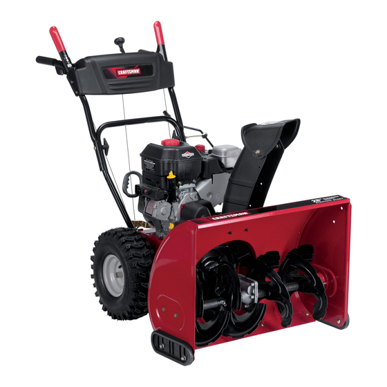
28" SNOW THROWER
Model No. 247.88690
CAUTION: Before using
this product, read this
manual and follow all
safety rules and operating
instructions.
Sears, Roebuck and Co., Hoffman Estates, IL 60179, U.S.A.
®
Visit our website: www.craftsman.com
• SAFETY
• ASSEMBLY
• OPERATION
• MAINTENANCE
• PARTS LIST
• ESPAÑOL
FORM NO. 769-03973
2/4/2009
Advertisement
Chapters
Table of Contents

Related Manuals for Craftsman 247.88690


Summary of Contents for Craftsman 247.88690
- Page 1 Operator’s Manual ® 28” SNOW THROWER Model No. 247.88690 • SAFETY • ASSEMBLY • OPERATION • MAINTENANCE • PARTS LIST CAUTION: Before using • ESPAÑOL this product, read this manual and follow all safety rules and operating instructions. Sears, Roebuck and Co., Hoffman Estates, IL 60179, U.S.A.
-
Page 2: Table Of Contents
This charge will be waived if you transport the snow thrower to an authorized Craftsman drop-off location. For the nearest authorized location, call 1-800-4-MY-HOME®. This warranty covers ONLY defects in material and workmanship. Sears will NOT pay for: •... -
Page 3: Safe Operation Practices
SAFETY INSTRUCTIONS Warning danger This machine was built to be operated according to the safe opera- This symbol points out important safety instructions which, if not tion practices in this manual. As with any type of power equipment, followed, could endanger the personal safety and/or property of carelessness or error on the part of the operator can result in serious yourself and others. - Page 4 SAFETY INSTRUCTIONS Safe Handling of Gasoline • Exercise extreme caution when operating on or crossing gravel surfaces. Stay alert for hidden hazards or traffic. To avoid personal injury or property damage use extreme care in handling gasoline. Gasoline is extremely flammable and the vapors are •...
- Page 5 SAFETY INSTRUCTIONS maintenanCe & storage do not modify engine • Never tamper with safety devices. Check their proper operation To avoid serious injury or death, do not modify engine in any way. regularly. Refer to the maintenance and adjustment sections of Tampering with the governor setting can lead to a runaway engine and this manual.
- Page 6 SAFETY INSTRUCTIONS safety symboLs This page depicts and describes safety symbols that may appear on this product. Read, understand, and follow all instructions on the machine before attempting to assemble and operate. Symbol Description READ THE OPERATOR’S MANUAL(S) Read, understand, and follow all instructions in the manual(s) before attempting to assemble and operate WARNING—...
-
Page 7: Safety Labels
SAFETY LABELS DANGER DANGER KEEP AWAY FROM ROTATING IMPELLER AND AUGER. CONTACT WITH IMPELLER OR AUGER CAN AMPUTATE HANDS AND FEET. USE CLEAN-OUT TOOL TO UNCLOG DISCHARGE CHUTE. DISENGAGE CLUTCH LEVERS, STOP ENGINE , AND REMAIN BEHIND HANDLES UNTIL ALL MOVING PARTS HAVE STOPPED BEFORE UNCLOGGING OR SERVICING MACHINE. -
Page 8: Assembly
ASSEMBLY NOTE: References to right or left side of the snow thrower are determined from behind the unit in the operating position (standing directly behind the snow thrower, facing the handle panel). remoVing from Carton Cut the corners of the carton and lay the sides flat on the ground. Remove and discard all packing inserts. - Page 9 ASSEMBLY Position the chute assembly over the base. See Figure 3. Close the flange keepers to secure the chute assembly to the chute base. See Figure 4. The flange keepers will click into place when properly secure. NOTE: If the flange keepers will not easily click into place, use the palm of your hand to apply swift, firm pressure to the back of each.
- Page 10 ASSEMBLY set-UP Chute Clean-out tool A chute clean-out tool is fastened to the top of the auger housing with a mounting clip. See Figure 6. The tool is designed to clear a chute assembly of ice and snow. This item is fastened with a cable tie at the factory.
- Page 11 ASSEMBLY Chute assembly The distance snow is thrown can be adjusted by changing the angle of the chute assembly. To do so: Stop the engine by removing the ignition key and loosen the plastic wing knob found on the left side of the chute assembly. Pivot the chute upward or downward before retightening the wing knob.
-
Page 12: Operation
OFF position. Your snow thrower has two reverse (R) speeds. One (1) is the slower and two (2) is the faster. meets ansi safety standards Craftsman Snow Throwers conform to the safety standard of the American National Standards Institute (ANSI). - Page 13 OPERATION reCoiL starter HandLe driVe ControL/ aUger ControL LoCk This handle is used to manually start the engine. DRIVE eLeCtriC starter bUtton CONTROL Pressing the electric starter button engages the engine’s electric starter when plugged into a 120V power source. eLeCtriC starter oUtLet Requires the use of a three-prong outdoor extension cord (included) and a 120V power source/wall outlet.
- Page 14 OPERATION CLean-oUt tooL Warning Warning Use extreme care when handling gasoline. Gasoline is extremely flammable and the vapors are explosive. Never fuel the machine Never use your hands to clear a clogged chute assembly. Shut indoors or while the engine is hot or running. Extinguish cigarettes, off engine and remain behind handles until all moving parts have cigars, pipes and other sources of ignition.
- Page 15 OPERATION Push starter button to start engine. NOTE: NEVER reposition the shift lever (change speeds or direction of travel) without first releasing the drive control and bringing the snow CaUtion thrower to a complete stop. Doing so will result in premature wear to the snow thrower’s drive system.
-
Page 16: Service & Maintenance
SERVICE AND MAINTENANCE maintenanCe sCHedULe Warning Before performing any type of maintenance/service, disengage all Follow the maintenance schedule given below. This chart describes controls and stop the engine. Wait until all moving parts have come to service guidelines only. Use the Service Log column to keep track of completed maintenance tasks. - Page 17 SERVICE AND MAINTENANCE With engine OFF but still warm, remove oil drain plug and drain oil into an appropriate receptacle. See Figure 13. CAUTION Oil FIll Used oil is a hazardous waste product. Dispose of used oil properly. Do not discard with household waste. Check with your local authori- ties or Sears Service Center for safe disposal/recycling facilities.
- Page 18 SERVICE AND MAINTENANCE engine speed Warning To avoid serious injury or death, DO NOT modify engine in any way. Tampering with the governor setting can cause the engine and equipment to operate at unsafe speeds. NEVER tamper with factory setting of engine governor. Running the engine faster than the speed set at the factory is dangerous.
- Page 19 SERVICE AND MAINTENANCE adjUstments shift Cable If the full range of speeds (forward and reverse) cannot be achieved, refer to the figure to the right and adjust the shift cable as follows: fastest (F6) forward speed position. Place the shift lever in the Loosen the hex nut on the shift cable index bracket.
- Page 20 SERVICE AND MAINTENANCE auger Control Refer to the Assembly section for instructions on adjusting the auger control cable. skid shoes Refer to the Assembly section for instructions on adjusting the skid shoes. beLt rePLaCement auger belt To remove and replace your snow thrower’s auger belt, proceed as follows: To prevent spillage, remove all fuel from tank by running engine until it stops.
- Page 21 SERVICE AND MAINTENANCE Remove the belt as follows. Refer to Figure 25. Loosen and remove the shoulder screw which acts as a belt keeper. Unhook the support bracket spring from the frame. Remove the belt from around the auger pulley, and slip the belt between the support bracket and the auger pulley.
- Page 22 SERVICE AND MAINTENANCE Carefully pivot the snow thrower up and forward so that it rests on the auger housing. Remove the frame cover from the underside of the snow thrower by removing four self-tapping screws which secure it. Refer to Figure 24.
- Page 23 SERVICE AND MAINTENANCE NOTE: Be careful not to damage the threads on the shaft. Carefully position the hex shaft downward and to the left before carefully sliding the friction wheel assembly off the shaft. See Figure 31. NOTE: If you’re replacing the friction wheel assembly as a whole, discard the worn part and slide the new part onto the hex shaft.
-
Page 24: Off-Season Storage
OFF-SEASON STORAGE If the snow thrower will not be used for 30 days or longer, or if it is the end of the snow season when the last possibility of snow is gone, the equipment needs to be stored properly. Follow storage instructions below to ensure top performance from the snow thrower for many more years. PreParing snoW tHroWer PreParing engine •... -
Page 25: Troubleshooting
TROUBLESHOOTING Problem Cause remedy Engine fails to start Choke control not in ON position Move choke control to ON position. Spark plug wire disconnected Connect wire to spark plug. Faulty spark plug Clean, adjust gap, or replace. Fuel tank empty or stale fuel Fill tank with clean, fresh gasoline. -
Page 26: Parts List
PARTS LIST Craftsman Snow Thrower Model 247.88690 9 19... - Page 27 PARTS LIST Craftsman Snow Thrower Model 247.88690 Ref. No. Part No. Description Ref. No. Part No. Description 731-2635 Snow Removal Tool Mount 684-04107-0637 Spiral Assembly, LH 684-04057A-0637 Impeller Assembly, 12” Dia. 684-04108-0637 Spiral Assembly, RH 710-0347 Hex Screw, 3/8-16, 1.75, Gr5 731-04870 Spacer, 1.25 OD x .75 ID x 1.00...
- Page 28 PARTS LIST Craftsman Snow Thrower Model 247.88690...
- Page 29 PARTS LIST Craftsman Snow Thrower Model 247.88690 Ref. No. Part No. Description Ref. No. Part No. Description 731-04869 Chute, Flange Keeper 631-04133A Handle Assembly, Clutch Lock, LH 746-04397 Cable, Speed Selector 631-04134B Handle Assembly, Clutch Lock, RH 749-04191A-0637 Handle, Upper, LH 684-04111B Handle Ass’y, Engage, LH...
- Page 30 PARTS LIST Craftsman Snow Thrower Model 247.88690 24 30 26 13...
- Page 31 PARTS LIST Craftsman Snow Thrower Model 247.88690 Ref. No. Part No. Description Ref. No. Part No. Description 656-04025A Disc Assembly, Friction Wheel 634-04148A-0911 RH Wheel Assembly, 15 x 5 x 6 684-04153 Friction Wheel Assembly, 5.5 OD 731-04873 Spacer, 1.25 x .75 x 3.0...
- Page 32 PARTS LIST Craftsman engine model 15C103-0661 for snow thrower model 247.88690 1058 OPERATOR’S MANUAL 48 SHORT BLOCK 1330 REPAIR MANUAL 1329 REPLACEMENT ENGINE 307A 1427 358 ENGINE GASKET SET 1022...
- Page 33 PARTS LIST Craftsman engine model 15C103-0661 for snow thrower model 247.88690 1026 1029 1022 1034 1095 VALVE GASKET SET 1023 914A 1022 914B 1022...
- Page 34 PARTS LIST Craftsman engine model 15C103-0661 for snow thrower model 247.88690 1196A 731A 1196 1251A 1070 1005 1252A 1036 EMISSIONS LABEL 1252 1251...
- Page 35 PARTS LIST Craftsman engine model 15C103-0661 for snow thrower model 247.88690 1230 1054 1347 1009 121 CARBURETOR OVERHAUL KIT 1210 1211...
- Page 36 PARTS LIST Craftsman engine model 15C103-0661 for snow thrower model 247.88690 Ref. No. Part No. Description Ref. No. Part No. Description 794188 Cylinder Assembly 690937 Screw (Rewind Starter) (SAE) 399269 Kit-Bushing/Seal (Magneto Side) 699228 Screw (Rewind Starter) (Metric) 299819s •...
- Page 37 PARTS LIST Craftsman engine model 15C103-0661 for snow thrower model 247.88690 Ref. No. Part No. Description Ref. No. Part No. Description 699480 Screw (Blower Housing) 793134 Cover-Control 695710 Shield-Cylinder 604A 790473 Cover-Control 699483 Screw (Cylinder Shield) (M4) 699335 Starter-Rewind 307A...
- Page 38 PARTS LIST Craftsman engine model 15C103-0661 for snow thrower model 247.88690 Ref. No. Part No. Description 794696 Key Set 694088 Gasket-Cylinder Head Plate 794687 Shield-Carburetor 794701 Pipe-Oil 1005 692592 Fan-Flywheel 1009 790537 Screw (Starter Motor) 1022 691890 •+ Gasket-Rocker Cover...
- Page 39 NOTES...
- Page 40 (This page applicable in the U.S.A. and Canada only.) sears, roebuck and Co., U.s.a. (sears), the California air resources board (Carb) and the United states environmental Protection agency (U.s. ePa) emission Control system Warranty statement (owner’s defect Warranty rights and obligations) EMISSION CONTROL WARRANTY COVERAGE IS APPLICABLE TO CERTI- YEAR 1997 AND LATER ENGINES WHICH ARE PURCHASED AND USED FIED ENGINES PURCHASED IN CALIFORNIA IN 1995 AND THEREAF-...
- Page 41 Look for relevant emissions durability Period and air index information on your engine emissions Label Engines that are certified to meet the California Air Resources Board (CARB) Tier 2 Emission Standards must display information regarding the Emissions Durability Period and the Air Index. Sears, Roebuck and Co., U.S.A. makes this information available to the consumer on our emission labels.
-
Page 42: Repair Protection Agreement
REPAIR PROTECTION AGREEMENT Congratulations on making a smart purchase. Your new Craftsman® Once you purchase the Agreement, a simple phone call is all that it product is designed and manufactured for years of dependable opera- takes for you to schedule service. You can call anytime day or night, or tion. -
Page 43: Español
Almacenamiento fuera de temporada ..Página 64 posterior DECLARACIÓN DE GARANTÍA garantía Limitada Craftsman dos años en Lanzador de nieve Cuando hecho funcionar y mantenido según todas las instrucciones suministradas, si este lanzador de nieve falla debido a un defecto en mate- rial o habilidad dentro de dos años de la fecha o compra, llame 1-800-4MYHOME hacer los arreglos para reparación libre. -
Page 44: Prácticas Operación Seguras
INSTRUCCIONES DE SEGURIDAD adVertenCia PeLigro Esta máquina fue construida para ser operada de acuerdo con La presencia de este símbolo indica que se trata de instrucciones las reglas de seguridad contenidas en este manual. Al igual que importantes de seguridad que se deben respetar para evitar con cualquier tipo de equipo motorizado, un descuido o error por poner en peligro su seguridad personal y/o material y la de otras parte del operador puede producir lesiones graves. - Page 45 INSTRUCCIONES DE SEGURIDAD Manejo seguro de la gasolina • Nunca opere la máquina si falta un montaje del canal o si el mismo está dañado. Mantenga todos los dispositivos de seguri- Para evitar lesiones personales o daños materiales tenga mucho dad en su lugar y en funcionamiento.
- Page 46 INSTRUCCIONES DE SEGURIDAD • Para encender el motor, jale de la cuerda lentamente hasta que • Según la Comisión de Seguridad de Productos para el Consu- sienta resistencia, luego jale rápidamente. El repliegue rápido de midor de los Estados Unidos (CPSC) y la Agencia de Protección la cuerda de arranque (tensión de retroceso) le jalará...
- Page 47 INSTRUCCIONES DE SEGURIDAD símboLos de segUridad Esta página describe los símbolos y figuras de seguridad internacionales que pueden aparecer en este producto. Lea el manual del operador para obtener la información terminada sobre seguridad, reunirse, operación y mantenimiento y reparación. Símbolo Descripción LEA EL MANUAL DEL OPERADOR (S)
-
Page 48: Montaje
MONTAJE NOTA: las referencias al lado derecho o y ciertos de la máquina quitanieve se determinan desde la parte posterior de la unidad en posición de operación (permaneciendo directamente detrás de la máquina quitanieve, mirando hacia el panel de la manija). extraCCión de La Unidad de La Caja Corte las esquinas de la caja de cartón y extiéndala en el piso Quite y descarte todos los insertos de empaque. - Page 49 MONTAJE Sitúe el montaje del canal sobre la base. Vea la figura 3. Cierre los fijadores de la brida para asegurar el montaje del canal a la base del canal. Vea la figura 4. Los fijadores de la brida emiten un chasquido cuando están bien asegurados. NOTA: si los fijadores de la brida no se ajustan en su lugar fácilmente, utilice la palma de su mano para aplicar una presión rápida y firme en la parte posterior de cada uno.
- Page 50 MONTAJE ConfigUraCión Herramienta de Limpieza del Canal Hay una herramienta de limpieza del canal iajustada a la parte superior de la caja de la barrena con un pasador de ensamblado. Vea la figura 6. La herramienta está diseñada para limpiar el hielo y la nieve del montaje de un canal.
- Page 51 MONTAJE ajuste del montaje del canal Es posible ajustar la distancia a la cual se arroja la nieve cambiando el ángulo del montaje del canal. Para hacerlo: Detenga el motor quitando la llave de encendido y afloje la perilla a mariposa de plástico que se encuentra en el lado izquierdo del montaje del canal.
-
Page 52: Operación
Hay dos velocidades de retroceso (R). La uno (1) es la más lenta, y la dos (2) es la más rápida. Cumple con los estándares de seguridad de ansi Las máquinas quitanieve de Craftsman cumplen con los estándares de seguridad del instituto estadounidense de estándares nacionales (ANSI). - Page 53 OPERACIÓN ControL de La barrena manija deL arranCador de retro- CONTROL DE Ceso LA BARRENA Esta manija se utiliza para arrancar el motor manualmente. botón deL arranCador eLéCtriCo Si oprime el botón del arrancador eléctrico se engrana el arrancador eléctrico del motor cuando se lo enchufa a una fuente de energía de 120V.
- Page 54 OPERACIÓN ControL direCCionaL deL CanaL antes de enCender eL motor adVertenCia CONTROL DIRECCIONAL DEL CANAL Lea, comprenda y siga todas las instrucciones y advertencias que INCLINACIÓN DEL aparecen en la máquina y en este manual antes de operarla. CANAL AJUSTABLE DESCARGA DESCARGA IZQUIERDA...
- Page 55 OPERACIÓN arrancador eléctrico Tire de la manija del arrancador con un movimiento firme y rápido. No suelte la manija ni permita que se desenganche. Determine si el cableado de su hogar es un sistema de tres cables Mantenga la manija del arrancador firmemente sujeta y permita conectado a tierra.
-
Page 56: Servicio Y Mantenimiento
SERVICIO Y MANTENIMIENTO Lista de mantenimiento adVertenCia Antes de realizar cualquier tipo del mantenimiento/servicio, suelte Siga la lista de mantenimiento dada abajo. Esta carta describe pautas todos los mandos y pare el motor. Espere hasta que todas las partes de servicio sólo. Use la columna de Tronco de Servicio para guardar de movimiento hayan venido a una parada completa. - Page 57 SERVICIO Y MANTENIMIENTO Cambio de aceite del motor Para evitar que el motor resulte dañado, es importante que: • Controle el nivel de aceite antes de cada uso y cada ocho horas Tapón de Ilenado de operación. de aceite • Cambie el aceite después de las 5 a 8 primeras horas de operación y después de cada 50 horas de operación o una vez por temporada.
- Page 58 SERVICIO Y MANTENIMIENTO Una el botón de control de estárter al eje de estárter en el carburador. Si el botón de control de estárter no es instalado correctamente, el estárter no funcionará. Instale la llave de seguridad. NOTA: Para el reemplazo se debe utilizar una bujía de resistor. Contacte con un centro de partes y reparación Sears o 1-800-4-MY- HOME®...
- Page 59 SERVICIO Y MANTENIMIENTO Monte las nuevas zapatas antideslizantes con cuatros pernos de carro (dos en cada lado), arandelas, y las tuercas de brida hexagonales. Consulte la figura 17. Para retirar la placa de raspado: Quite los pernos de carro y las tuercas hexagonales que la sujetan a la caja de la máquina quitanieve.
- Page 60 SERVICIO Y MANTENIMIENTO soporte del canal Si la espiral situada en la parte inferior del control direccional del canal no se engancha completamente con el montaje del canal, es posible ajustar el soporte del canal. Para hacerlo: Afloje las dos tuercas que sujetan el soporte del canal y cambie su posición ligeramente.
- Page 61 SERVICIO Y MANTENIMIENTO Afloje y retire el tornillo con reborde que actúa como guarda de la correa. Vea la figura 24. Desenganche el resorte de la ménsula de soporte del marco. Retire la correa de alrededor de la polea de la barrena y deslice la misma entre la ménsula de soporte y la polea de la barrena.
- Page 62 SERVICIO Y MANTENIMIENTO 4. Gire con cuidado la máquina quitanieve hacia arriba y hacia delante de manera que quede apoyada sobre la caja de la barrena. 5. Saque la cubierta del marco desde debajo de la máquina quita nieve retirando los cuatro tornillos autorroscantes que la aseguran.
- Page 63 SERVICIO Y MANTENIMIENTO NOTA: Tenga cuidado de no dañar las roscas del eje. Con cuidado, ubique el eje hexagonal hacia abajo y hacia la izquierda antes de deslizar con precaución el montaje de la rueda de fricción fuera del eje. Vea la figura 30. NOTA: Cuando se desea reemplazar el conjunto de la rueda de fricción completo, descarte la pieza desgastada y deslice la nueva pieza en el eje hexagonal.
-
Page 64: Almacenamiento Fuera De Temporada
ALMACENAMIENTO FUERA DE TEMPORADA Si no se va a utiliza el equipo durante 30 días o más, o si es el final de la temporada de nieve y ya no existe posibilidad de que nieve, es necesario almacenar el equipo de manera adecuada. Siga las instrucciones de almacenamiento que se indican a continuación para garantizar el rendimiento máximo de la máquina quitanieve durante muchos años . -
Page 65: Solución De Problemas
SOLUCIÓN DE PROBLEMAS Problema Causa remedio El motor no arranca La palanca de obturación no está en la Ponga el interruptor en la posición CHOKE (obtura- posición ON (encendido) ción). Se ha desconectado el cable de la bujía Conecte el cable a la bujía. La bujía no funciona correctamente Limpie, ajuste la distancia disruptiva o cambie. - Page 66 SOLUCIÓN DE PROBLEMAS Problema Causa remedio Pérdida de potencia El cable de la bujía está flojo Conecte y ajuste el cable de la bujía. El orificio de ventilación del tapón de Retire el hielo y la nieve del tapón de llenado del llenado del combustible está...
- Page 67 (Esta página se aplica sólo en EE.UU. y Canadá). sears, roebuck and Co., U.s.a. (sears), el Consejo de recursos ambientales de California (Carb) y la agencia de Protección ambiental de los estados Unidos (ePa) declaración de garantía del sistema de control de emisiones (derechos y obligaciones de la garantía de defectos del propi- etario) LA COBERTURA DE LA GARANTÍA DE CONTROL DE EMISIONES ES Y PARA LOS MODELOS CERTIFICADOS DEL AÑO 1997 Y POSTERIORES,...
- Page 68 busque el período de duración de emisiones importantes yla información de clasificación de aire en la etiqueta de emisiones de su motor Los motores cuyo cumplimiento con los estándares de emisión Tier 2 de la Comisión de Recursos Ambientales de California (CARB) esté...
-
Page 69: Acuerdo De Protección Para Reparaciones
Felicitaciones por haber realizado una adquisición inteligente. El Una vez adquirido el Acuerdo, puede programar el servicio con producto Craftsman® que ha adquirido está diseñado y fabricado tan sólo realizar una llamada telefónica. Puede llamar en cualquier para brindar muchos años de funcionamiento confiable. Pero como momento del día o de la noche o programar un servicio en línea. - Page 70 NOTAS...
- Page 71 NOTAS...
- Page 72 Your Home For expert troubleshooting and home solutions advice: www.managemyhome.com For repair – in your home – of all major brand appliances, lawn and garden equipment, or heating and cooling systems, no matter who made it, no matter who sold it! For the replacement parts, accessories and owner’s manuals that you need to do-it-yourself.
Need help?
Do you have a question about the 247.88690 and is the answer not in the manual?
Questions and answers