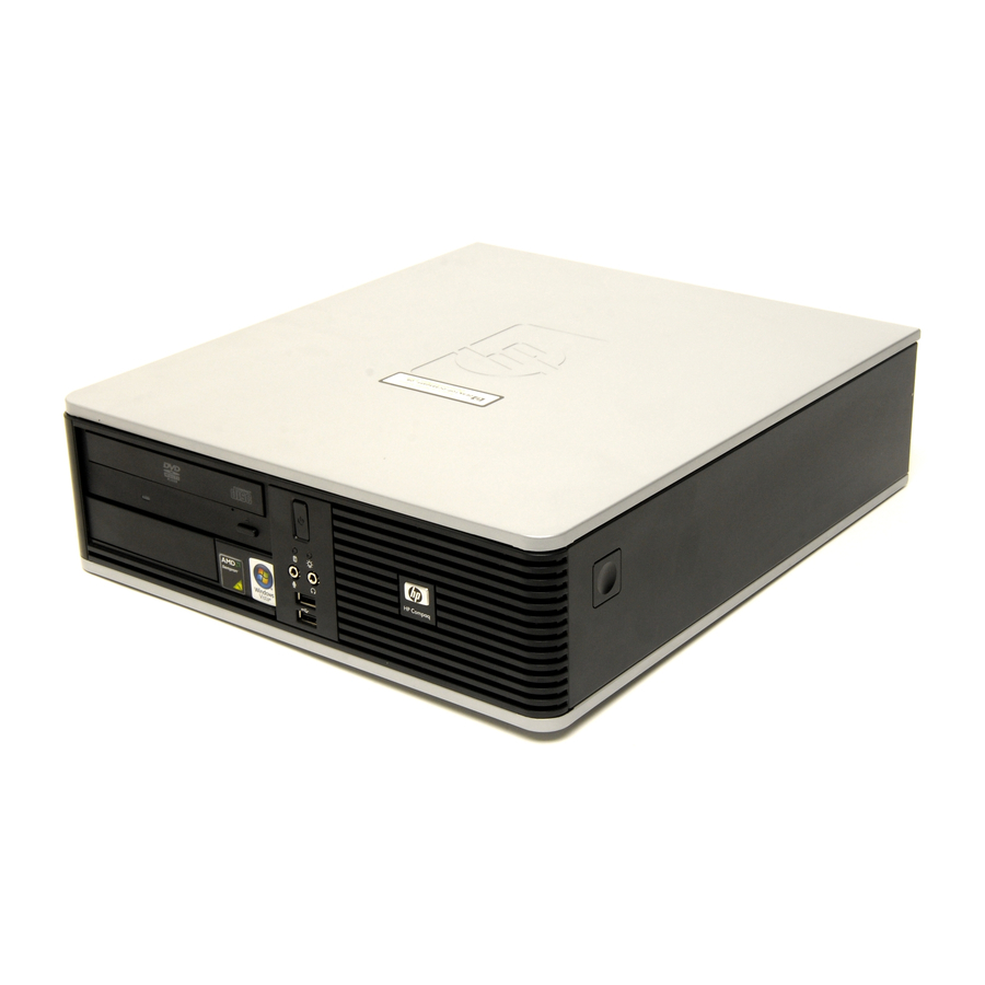
Compaq dc5850 - Microtower PC Technical Reference Manual
Dc5850 series business desktop computers
Hide thumbs
Also See for dc5850 - Microtower PC:
- Troubleshooting manual (69 pages) ,
- Hardware reference manual (58 pages) ,
- Use manual (22 pages)
Table of Contents
Advertisement
Quick Links
Technical Reference Guide
HP Compaq dc5850 Series
Business Desktop Computers
Document Part Number: 512751-001
October 2008
This document provides information on the design, architecture, function,
and capabilities of the HP Compaq dc5850 Series Business Desktop
Computers. This information may be used by engineers, technicians,
administrators, or anyone needing detailed information on the products
covered.
Advertisement
Table of Contents

Related Manuals for Compaq dc5850 - Microtower PC


Summary of Contents for Compaq dc5850 - Microtower PC
- Page 1 Document Part Number: 512751-001 October 2008 This document provides information on the design, architecture, function, and capabilities of the HP Compaq dc5850 Series Business Desktop Computers. This information may be used by engineers, technicians, administrators, or anyone needing detailed information on the products...
- Page 2 This document contains proprietary information that is protected by copyright. No part of this document may be photocopied, reproduced, or translated to another language without the prior written consent of Hewlett-Packard Company. Technical Reference Guide HP Compaq dc5850 Series Business Desktop Computers First Edition (October 2008) Document Part Number: 512751-001...
-
Page 3: Table Of Contents
Contents 1 Introduction 1.1 About this Guide ............. 1–1 1.1.1 Online Viewing . - Page 4 Contents 4 System Support 4.1 Introduction ..............4–1 4.2 PCI Bus Overview .
- Page 5 Contents 5.9 Network Interface Controller........... 5–16 5.9.1 Wake-On-LAN Support .
- Page 6 Contents 8 SYSTEM BIOS 8.1 Introduction ..............8–1 8.2 ROM Flashing .
-
Page 7: Introduction
Introduction About this Guide This guide provides technical information about HP Compaq dc5850 Business PC personal computers that feature AMD processors and the AMD 780V chipset. This document describes in detail the system's design and operation for programmers, engineers, technicians, and system administrators, as well as end-users wanting detailed information. -
Page 8: Serial Number
Introduction Serial Number The serial number is located on a sticker placed on the exterior cabinet. The serial number is also written into firmware and may be read with HP Diagnostics or Insight Manager utilities. Notational Conventions The notational guidelines used in this guide are described in the following subsections. 1.4.1 Special Notices The usage of warnings, cautions, and notes is described as follows: WARNING: Text set off in this manner indicates that failure to follow directions could result in bodily... -
Page 9: Common Acronyms And Abbreviations
Introduction Common Acronyms and Abbreviations Table 1-1 lists the acronyms and abbreviations used in this guide. Table 1-1 Acronyms and Abbreviations Acronym or Abbreviation Description ampere alternating current ACPI Advanced Configuration and Power Interface analog-to-digital Analog-to-digital converter ADD or ADD2 Advanced digital display (card) Accelerated graphics port AHCI... -
Page 10: Acronyms And Abbreviations
1. coder/decoder 2. compressor/decompressor Compaq central processing unit CRIMM Continuity (blank) RIMM cathode ray tube 1. Compaq system management 2. Compaq server management digital-to-analog converter direct current DOS compatibility hole Display Data Channel Double data rate (memory) DIMM dual inline memory module... - Page 11 Introduction Table 1-1 (Continued) Acronyms and Abbreviations Acronym or Abbreviation Description EISA extended ISA enhanced parallel port EIDE enhanced IDE ESCD Extended System Configuration Data (format) Environmental Variable (data) ExCA Exchangeable Card Architecture FIFO first in/first out flag (register) frequency modulation fast page mode (RAM type) Floating point unit (numeric or math coprocessor) Frames per second...
- Page 12 Introduction Table 1-1 (Continued) Acronyms and Abbreviations Acronym or Abbreviation Description industry standard architecture Kb/KB kilobits/kilobytes (x 1024 bits/x 1024 bytes) Kb/s kilobits per second kilogram kilohertz kilovolt pound local area network liquid crystal display light-emitting diode Low pin count large scale integration LSb/LSB least significant bit/least significant byte...
- Page 13 Introduction Table 1-1 (Continued) Acronyms and Abbreviations Acronym or Abbreviation Description 1. programmable array logic 2. phase alternating line PATA Parallel ATA Personal computer Printed circuit assembly peripheral component interconnect PCI-E PCI Express pulse code modulation PCMCIA Personal Computer Memory Card International Association PCI express graphics Power factor correction personal identification number...
- Page 14 Introduction Table 1-1 (Continued) Acronyms and Abbreviations Acronym or Abbreviation Description SDVO Serial digital video output Single Edge-Connector SECAM sequential colour avec memoire (sequential color with memory) sign flag SGRAM Synchronous Graphics RAM SIMD Single instruction multiple data SIMM single in-line memory module SMART Self Monitor Analysis Report Technology system management interrupt...
- Page 15 Introduction Table 1-1 (Continued) Acronyms and Abbreviations Acronym or Abbreviation Description Uniform resource locator microsecond us/µs Universal Serial Bus unshielded twisted pair volt Volts alternating current Volts direct current VESA Video Electronic Standards Association video graphics adapter VLSI very large scale integration VRAM Video RAM watt...
- Page 16 Introduction 1-10 www.hp.com Technical Reference Guide...
- Page 17 System Overview Introduction The HP Compaq dc5850 Business PC personal computers (Figure 2-1) deliver an outstanding combination of manageability, serviceability, and compatibility for enterprise environments. Based on an AMD processor with the AMD 780V chipset, these systems emphasize performance along with industry compatibility. These models feature a similar architecture incorporating both PCI 2.3 and PCIe 1.1 buses.
-
Page 18: System Overview
System Overview 2.2 Features The following standard features are included on all models unless otherwise indicated: ■ Supports one of the following AMD processors installed in an AM2+ socket: ❏ AMD Phenom™ Quad-Core with HyperTransport Technology ❏ AMD Phenom Triple-Core with HyperTransport Technology ❏... - Page 19 System Overview Table 2-1 shows the differences in features between the different PC series based on form factor: Table 2-1 Feature Difference Matrix by Form Factor Drive bays: Externally accessible 3.5-inch bay Externally accessible 5.25-inch bay Internal 3.5-inch bay Drive types supported: PCIe slots: x16 graphics (PCIe 2.0) 1 low-profile [1]...
-
Page 20: System Architecture
System Overview 2.3 System Architecture The systems covered in this guide feature an architecture based on an AMD processor and chipset (Figure 2-2). All systems covered in this guide include the following key components: ■ AMD Phenom, Athlon, or Sempron processor. ■... - Page 21 [1] 2 front ports, 6 rear ports, 2 internal ports [2] 2nd serial port requires optional bracket/cable assembly [3] Parallel port functionality requires optional bracket/cable assembly Figure 2-2. HP Compaq dc5850 Business PC Architecture, Block diagram Technical Reference Guide www.hp.com...
-
Page 22: Amd Processor Support
System Overview 2.3.1 AMD Processor Support The models covered in this guide are designed to support the following processor types: ■ AMD Phenom X4 Quad-Core with HyperTransport Technology ■ AMD Phenom X3 Triple-Core with HyperTransport Technology ■ AMD Athlon X2 Dual-Core with HyperTransport Technology ■... -
Page 23: Support Components
System Overview 2.3.3 Support Components Input/output functions not provided by the chipset are handled by other support components. Some of these components also provide “housekeeping” and various other functions as well. Table 2-3 shows the functions provided by the support components. Table 2-3 Support Component Functions Component Name... -
Page 24: Mass Storage
System Overview 2.3.5 Mass Storage These systems provide four SATA interfaces for mass storage devices. The SFF supports up to two removeable media devices and one internal hard drive. The MT supports up to three removeable media devices and two hard drives, and is available in factory-preconfigured RAID configurations. -
Page 25: Integrated Graphics Processor
System Overview 2.3.9 Integrated Graphics Processor These systems use the AMD RS780 component, which uses an ATI Radeon 3100 integrated graphics processor featuring DirectX 10 technology that can drive an analog VGA monitor and a DVI-D monitor. Table 2-4 lists the key features of the integrated graphics processor. Table 2-4 Integrated Graphics Subsystem Statistics Integrated Graphics Controller... -
Page 26: Specifications
System Overview 2.4 Specifications This section includes the environmental, electrical, and physical specifications for the systems covered in this guide. Where provided, metric statistics are given in parenthesis. Specifications are subject to change without notice. Table 2-5 Environmental Specifications (Factory Configuration) Parameter Operating Non-operating... -
Page 27: Physical Specifications
System Overview Table 2-7 Physical Specifications Parameter SFF [2] MT [3] Height 3.95 in 14.85 in (10.03 cm) (37.72 cm) Width 13.3 in 6.95 in (33.78 cm) (17.65 cm) Depth 14.9 in 16.85 in (37.85 cm) (42.80 cm) Weight [1] 17.86 lb 23.44 lb (8.10 kg) - Page 28 System Overview 2-12 www.hp.com Technical Reference Guide...
-
Page 29: Processor/Memory Subsystem
Processor/Memory Subsystem Introduction This chapter describes the processor/memory subsystem. This systems support the AMD Phenom, Athlon, and Sempron processor families. As shown in Figure 3-1, these processors use an integrated DDR2 memory controller and communicate with the chipset through the HyperTranport interface (I/F). -
Page 30: Amd Processors
Processor/Memory Subsystem 3.2 AMD Processors These systems feature an AMD processor mounted with a heat sink in an AM2+ socket. The mounting socket allows the processor to be easily changed for upgrading. 3.2.1 AMD Processor Overview The systems covered in this guide support AMD Phenom, Athlon, and Sempron processors. Key features of these AMD processors include: ■... -
Page 31: Memory Subsystem
Processor/Memory Subsystem 3.3 Memory Subsystem All models support up to 8 gigabytes of non-ECC PC2-6400 and PC2-5300 DDR2 memory. ✎ The DDR2 SDRAM “PCxxxx” reference designates bus bandwidth (i.e., a PC2-6400 module can, operating at a 800-MHz effective speed, provide a throughput of 6400 MBps (8 bytes × 800 MHz)). -
Page 32: Memory Upgrading
Processor/Memory Subsystem 3.3.1 Memory Loading/Upgrading Table 3-2 shows suggested memory configurations for these systems. CAUTION: Always power down the system and disconnect the power cord from the AC outlet before adding or replacing memory modules. Changing memory modules while the unit is plugged into an active AC outlet could result in equipment damage. - Page 33 Processor/Memory Subsystem 8 GB 1 FFFF FFFEh 4.2 GB FFE0 0000h High BIOS Area 4 GB F000 0000h Memory Area 256 MB Main Memory 32 MB Area Main Memory 0100 0000h 16 MB 00FF FFFFh Main Memory 0010 0000h 1 MB 000F FFFFh BIOS Extended BIOS...
- Page 34 Processor/Memory Subsystem www.hp.com Technical Reference Guide...
-
Page 35: Pci Bus Overview
System Support Introduction This chapter covers subjects dealing with basic system architecture and covers the following topics: ■ PCI bus overview (4.2) ■ System resources (4.3) ■ Real-time clock and configuration memory (4.4) ■ System management (4.5) ■ Register map and miscellaneous functions (4.6) This chapter covers functions provided by off-the-shelf chipsets and therefore describes only basic aspects of these functions as well as information unique to the systems covered in this guide. -
Page 36: Pci Express Bus Operation
System Support The PCI bus supports a bus master/target arbitration scheme. A bus master is a device that has been granted control of the bus for the purpose of initiating a transaction. A target is a device that is the recipient of a transaction. The Request (REQ), Grant (GNT), and FRAME signals are used by PCI bus masters for gaining access to the PCI bus. -
Page 37: Option Rom Mapping
System Support Link Layer The link layer provides data integrity by adding a sequence information prefix and a CRC suffix to the packet created by the transaction layer. Flow-control methods ensure that a packet will only be transferred if the receiving device is ready to accomodate it. A corrupted packet will be automatically re-sent. -
Page 38: Pci Connectors
System Support 4.2.6 PCI Connectors PCI 2.3 Connector Figure 4-2. 32-bit, 5.0-volt PCI 2.3 Bus Connector Table 4-2. PCI 2.3 Bus Connector Pinout B Signal A Signal B Signal A Signal B Signal A Signal - 1 2 VDC TRST- AD28 +3.3 VDC +12 VDC... -
Page 39: Pci Express Connectors
System Support PCI Express Connectors x1 Connector x16 Connector Figure 4-3. PCI Express Bus Connectors Table 4-3. PCI Express Bus Connector Pinout B Signal A Signal B Signal A Signal B Signal A Signal +12 VDC PRSNT1# PERp3 PERn9 +12 VDC +12 VDC RSVD PERn3... -
Page 40: System Resources
System Support 4.3 System Resources This section describes the availability and basic control of major subsystems, otherwise known as resource allocation or simply “system resources.” System resources are provided on a priority basis through hardware interrupts and DMA requests and grants. 4.3.1 Interrupts The microprocessor uses two types of hardware interrupts;... -
Page 41: Direct Memory Access
System Support Table 4-4. PCI Interrupt Distribution System Interrupts System Board PIRQ PIRQ PIRQ PIRQ PIRQ PIRQ PIRQ PIRQ Connector PCI slot 1 (J20) The PCI interrupts can be configured by PCI Configuration Registers 60h..63h to share the standard ISA interrupts (IRQn). ✎... -
Page 42: Real-Time Clock And Configuration Memory
System Support 4.4 Real-Time Clock and Configuration Memory The Real-time clock (RTC) and configuration memory (also referred to as “CMOS”) functions are provided by the SB700 component and is MC146818-compatible. As shown in the following figure, the SB700 component provides 256 bytes of battery-backed RAM divided into two 128-byte configuration memory areas. -
Page 43: Standard Cmos Locations
System Support 4.4.2 Standard CMOS Locations Table 4-5 describes standard configuration memory locations 0Ah-3Fh. These locations are accessible through using OUT/IN assembly language instructions using port 70/71h or BIOS function INT15, AX=E823h. Table 4-5. Configuration Memory (CMOS) Map Location Function Location Function 00-0Dh... -
Page 44: Cable Lock Provision
System Support Power-On / Setup Password These systems include a power-on and setup passwords, which may be enabled or disabled (cleared) through a jumper on the system board. The jumper controls a GPIO input to the SB700 that is checked during POST. To clear the Power-On and/or Setup password, use the following procedure: 1. -
Page 45: Power Management
System Support 4.5.2 Power Management These systems provide baseline hardware support of ACPI-compliant firmware and software. Key power-consuming components (processor, chipset, I/O controller, and fan) can be placed into a reduced power mode either automatically or by user control. The system can then be brought back up (“wake-up”) by events defined by the ACPI 2.0 specification. -
Page 46: System Status
System Support 4.5.3 System Status These systems provide a visual indication of system boot, ROM flash, and operational status through the power LED and internal speaker, as described in Table 4-7. Table 4-7. System Operational Status LED Indications System Status PowerLED Beeps [2] Action Required... -
Page 47: Register Map And Miscellaneous Functions
System Support The RPM (speed) of all fans is the result of the temperature of the CPU as sensed by speed control circuitry. The fans are controlled to run at the slowest (quietest) speed that will maintain proper cooling. Units using chassis and CPU fans must have both fans connected to their corresponding headers to ensure proper cooling of the system. -
Page 48: System I/O Map
System Support Table 4-8 System I/O Map I/O Port Function 0000..001Fh DMA Controller 1 0020..002Dh Interrupt Controller 1 002E, 002Fh Index, Data Ports to SIO Controller (primary) 0030..003Dh Interrupt Controller 0040..0042h Timer 1 004E, 004Fh Index, Data Ports to SIO Controller (secondary) 0050..0052h Timer / Counter 0060..0067h... -
Page 49: Gpio Functions
System Support 4.6.2 GPIO Functions SB700 Functions The SB700 South Bridge provides various functions through the use of programmable general purpose input/output (GPIO) ports. These systems use GPIO ports and associated registers of the for the following functions: ■ Chassis and board ID ■... - Page 50 System Support 4-16 www.hp.com Technical Reference Guide...
-
Page 51: Input/Output Interfaces
Input/Output Interfaces Introduction This chapter describes the standard interfaces that provide input and output (I/O) porting of data and that are controlled through I/O-mapped registers. The following I/O interfaces are covered in this chapter: ■ SATA interfaces (5.2) ■ Diskette drive interface (5.3) ■... -
Page 52: Sata Interface
Input/Output Interfaces 5.2 SATA Interfaces These systems provide four serial ATA (SATA) interfaces that support tranfer rates up to 3.0 Gb/s and offer RAID data protection functionality. The SATA interface duplicates most of the functionality of the EIDE interface through a register interface that is equivalent to that of the legacy IDE host adapter. - Page 53 NCQ or non-NCQ), and cache size. Detailed information on configuring these systems for RAID operations is contained in the white paper “AHCI and RAID on HP Compaq dc5850 Business PCs and Using AMD Array Management Software (RAIDXpert)” available at http://www.hp.com.
-
Page 54: Diskette Drive Interface
Input/Output Interfaces 5.3 Diskette Drive Interface These systems support a diskette drive through a standard 34-pin diskette drive connector. The diskette drive interface function is integrated into the super I/O (SIO) component. The internal logic of the SIO controller is software-compatible with standard 82077-type logic. The diskette drive controller has three operational phases in the following order: ■... - Page 55 Input/Output Interfaces These systems use a standard 34-pin connector for diskette drives (refer to Figure 5-2 and Table 5-2 for the pinout). Drive power is supplied through a separate connector. Figure 5-2. 34-Pin Diskette Drive Connector (P10 on system board). Table 5-2.
-
Page 56: Serial Interface
Input/Output Interfaces 5.4 Serial Interface Systems covered in this guide may include one RS-232-C type serial interface to transmit and receive asynchronous serial data with external devices. Some systems may allow the installation of a second serial interface through an optional bracket/cable assembly that attaches to header P52 on the system board. -
Page 57: Parallel Interface Support
Input/Output Interfaces 5.5 Parallel Interface Support These systems include a system board header (P125) that supports an optional parallel bracket/cable assembly that provides a parallel interface for a peripheral device such as a printer. The parallel interface supports bi-directional 8-bit parallel data transfers with a peripheral device. The parallel interface supports three main modes of operation: ■... -
Page 58: Parallel Interface Connector
Input/Output Interfaces 5.5.4 Parallel Interface Connector Figure 5-4 and Table 5-4 show the connector and pinout of the parallel connector provided on the optional parallel bracket/cable assembly. Note that some signals are redefined depending on the port's operational mode. Figure 5-4. DB-25 Parallel Interface Connector (provided on the optional bracket/cable assembly) Table 5-4. -
Page 59: Keyboard/Pointing Device Interface
Input/Output Interfaces 5.6 Keyboard/Pointing Device Interface The keyboard/pointing device interface function is provided by the SIO controller component, which integrates 8042-compatible keyboard controller logic (hereafter referred to as simply the “8042”) to communicate with the keyboard and pointing device using bi-directional serial data transfers. -
Page 60: Pointing Device Interface Operation
Input/Output Interfaces 5.6.2 Pointing Device Interface Operation The pointing device (typically a mouse) connects to a 6-pin DIN-type connector that is identical to the keyboard connector both physically and electrically. The operation of the interface (clock and data signal control) is the same as for the keyboard. The pointing device interface uses the IRQ12 interrupt. -
Page 61: Universal Serial Bus Interface
Input/Output Interfaces 5.7 Universal Serial Bus Interface The Universal Serial Bus (USB) interface provides asynchronous/isochronous data transfers with compatible peripherals such as keyboards, printers, or modems. This high-speed interface supports hot-plugging of compatible devices, making possible system configuration changes without powering down or even rebooting systems. These systems provide eight externally-accessible USB ports, two front panel USB ports (which may be disabled) and six USB ports on the rear panel. -
Page 62: Usb Cable Data
Input/Output Interfaces 5.7.2 USB Cable Data The recommended cable length between the host and the USB device should be no longer than sixteen feet for full-channel (12 MB/s) operation, depending on cable specification (see following table). Table 5-8. USB Cable Length Data Conductor Size Resistance Maximum Length... -
Page 63: Audio Subsystem
Input/Output Interfaces 5.8 Audio Subsystem These systems use the HD audio controller of the SB700 component to access and control an Analog Devices AD1884A HD Audio Codec, which provides 2-channel high definition analog-to-digital (ADC) and digital-to-analog (DAC) conversions. A block diagram of the audio subsystem is shown in Figure 5-8. -
Page 64: Hd Audio Controller
Input/Output Interfaces 5.8.1 HD Audio Controller The HD Audio Controller is a PCI Express device that is integrated into the SB700 component and supports the following functions: ■ Read/write access to audio codec registers ■ Support for greater than 48-KHz sampling ■... -
Page 65: Audio Specifications
Input/Output Interfaces 5.8.4 Audio Specifications The specifications for the HD Audio subsystem are listed in Table 5-10. Table 5-10. HD Audio Subsystem Specifications Parameter Measurement Sampling Rates: 44.1-, 48-, 96-, & 192-KHz 44.1-, 48-, 96-, & 192KHz Resolution: 24-bit 24-bit Nominal Input Voltage: Mic In (w/+20 db gain) .283 Vp-p... -
Page 66: Network Interface Controller
Input/Output Interfaces 5.9 Network Interface Controller These systems provide 10/100/1000 Mbps network support through a Broadcom BMC5754 network interface controller (NIC), a PHY component, and a RJ-45 jack with integral status LEDs (Figure 5-10). The support firmware is contained in the system (BIOS) ROM. The NIC can operate in half- or full-duplex modes, and provides auto-negotiation of both mode and speed. -
Page 67: Wake-On-Lan Support
Input/Output Interfaces 5.9.1 Wake-On-LAN Support The NIC supports the Wired-for-Management (WfM) standard of Wake-On-LAN (WOL) that allows the system to be booted up from a powered-down or low-power condition upon the detection of special packets received over a network. The NIC receives 3.3 VDC auxiliary power while the system unit is powered down in order to process special packets. -
Page 68: Nic Connector
Input/Output Interfaces 5.9.4 NIC Connector Figure 5-11 shows the RJ-45 connector used for the NIC interface. This connector includes the two status LEDs as part of the connector assembly. Activity LED Speed LED Description Transmit+ Transmit- Receive+ Receive- Pins 4, 5, 7, 8 not used 8 7 6 5 Figure 5-11. -
Page 69: Introduction
Integrated Graphics Processor Introduction This chapter describes the integrated graphics processor (IGP) of the HP dc5850 Personal Computer. This graphics subsystem employs the use of system memory to provide efficient, economical 2D and 3D performance. These systems provide dual-monitor support in the standard configuration and allow two methods for upgrading the IGP: ■... -
Page 70: Functional Description
Integrated Graphics Processor 6.2 Functional Description These systems include a graphics subsystem based on the ATI Radeon 3100 controller integrated into the AMD RS780 North Bridge (Figure 6-1). The ATI Radeon 3100 operates off the internal PCIe x16 bus and can directly drive an analog multi-scan monitor or a DVI-D-compatible digital monitor. -
Page 71: Upgrading
Integrated Graphics Processor 6.3 Upgrading All systems provide direct, dual-monitor support; a VGA montor and a DVI monitor can be connected and driven simultaneously. These systems also include a PCIe x16 graphics slot that specifically supports a PCIe x16 graphics card. The normal upgrade procedure for these systems is as follows: 1. -
Page 72: Monitor Connectors
Integrated Graphics Processor 6.4 Monitor Connectors These systems provide an analog VGA connector and a DVI-D connector and can drive both types of monitors simultaneously. 6.4.1 Analog Monitor Connector Figure 6-2 shows the analog VGA connector for attaching an analog video monitor: Figure 6-2. -
Page 73: Dvi-D Connector
Integrated Graphics Processor 6.4.2 DVI-D Connector Figure 6-3 shows the DVI-D connector for attaching a digital monitor. Figure 6-3. Female DVI-D Connector, (as viewed from rear of chassis). Table 6-2. DVI-D Monitor Connector Pinout Signal Signal TMDS Data 2- TMDS Data 3+ TMDS Data 2+ 5 VDC TMDS Dara 2 &... - Page 74 Integrated Graphics Processor www.hp.com Technical Reference Guide...
-
Page 75: Power And Signal Distribution
Power and Signal Distribution Introduction This chapter describes the power supplies and discusses the methods of general power and signal distribution. Topics covered in this chapter include: ■ Power distribution (7.2) ■ Power Control (7.3) ■ Signal distribution (7.4) Power Distribution Each form factor uses a unique power supply unit (PSU). -
Page 76: Sff Power Supply
Power and Signal Distribution 7.2.1 SFF Power Supply The SFF form factor comes standard with a 240-watt, active-PFC power supply unit with the specifications and cabling as indicated in the following table and figure. Table 7-1. SFF 240-Watt Power Supply Unit Specifications Min. -
Page 77: Mt Power Supply
Power and Signal Distribution 7.2.2 MT Power Supply The MT form factor comes standard with a 300-watt, passive-PFC power supply unit with the specifications and cabling as indicated in the following table and figure. Table 7-2. MT 300-Watt Power Supply Unit Specifications Min. -
Page 78: Optional Energy Star Compliant Psus
Power and Signal Distribution 7.2.3 Optional Energy Star Compliant PSUs Energy Star 4.0 (80-Plus, Bronze-compliant) active-PFC power supply units are available as an option for these systems. The specifications of the high-efficiency power supplies match those of the standard units except for the following aspects: ■... - Page 79 Power and Signal Distribution A dual-color LED located on the front panel (bezel) is used to indicate system power status. The front panel (bezel) power LED provides a visual indication of key system conditions listed as follows: Table 7-4. Power LED Indications Power LED Condition Steady green...
-
Page 80: Wake Up Events
Power and Signal Distribution 7.3.2 Wake Up Events The PS On signal can be activated with a power “wake-up” of the system due to the occurrence of a magic packet, serial port ring, or PCI power management event (PME). These events can be individually enabled through the Setup utility to wake up the system from a sleep (low power) state. -
Page 81: Power Management
Power and Signal Distribution 7.3.3 Power Management These systems include power management functions designed to conserve energy. These functions are provided by a combination of hardware, firmware (BIOS) and software. The system provides the following power management support: ■ ACPI v2.0 compliant (ACPI modes C1, S1, and S3-S5) ■... -
Page 82: Signal Distribution
Power and Signal Distribution Signal Distribution Table 7-6 lists key reference designators for LEDs, connectors, headers, and switches used on the system boards for systems covered in this guide. Unless otherwise indicated, components are used on all system boards. Table 7-6. System Board Component Designations Designator Component function... - Page 83 Power and Signal Distribution Figure 7-4 shows pinouts of headers used on the sytem boards. Power Button/LED, HD LED Front I/O USB Header P5 Header P5 HD LED + 1 +5 V fused 1 2 PS LED + 2 +5 V fused HD LED - 3 4 PS LED - USB port 8- 3...
- Page 84 Power and Signal Distribution 7-10 www.hp.com Technical Reference Guide...
-
Page 85: System Bios
SYSTEM BIOS Introduction The System Basic Input/Output System (BIOS) of the computer is a collection of machine language programs stored as firmware in read-only memory (ROM). The system BIOS includes such functions as Power-On Self Test (POST), PCI device initialization, Plug 'n Play support, power management activities, and the Setup utility. -
Page 86: Rom Flashing
SYSTEM BIOS 8.2 ROM Flashing The system BIOS firmware is contained in a flash ROM device that can be re-written with new BIOS code using a flash utility locally (with F10 setup), with the HPQFlash program in a Windows environment, or with the FLASHBIN.EXE utility in a DOS or DOS-like environment. 8.2.1 Upgrading Upgrading the BIOS is not normally required but may be necessary if changes are made to the unit's operating system, hard drive, or processor. -
Page 87: Boot Functions
SYSTEM BIOS 8.3 Boot Functions The BIOS supports various functions related to the boot process, including those that occur during the Power On Self-Test (POST) routine. 8.3.1 Boot Device Order The default boot device order is as follows: 1. CD-ROM drive (EL Torito CD images) 2. -
Page 88: Boot Error Codes
SYSTEM BIOS The BIOS performs memory detection and configuration with the following steps: 1. Program the buffer strength control registers based on SPD data and the DIMM slots that are populated. 2. Determine the common CAS latency that can be supported by the DIMMs. 3. -
Page 89: Client Management Functions
SYSTEM BIOS 8.4 Client Management Functions Table 8-2 provides a partial list of the client management BIOS functions supported by the systems covered in this guide. These functions, designed to support intelligent manageability applications, are HP-specific unless otherwise indicated. Table 8-2. Client Management Functions (INT15) Function Mode... -
Page 90: System Id And Rom Type
SYSTEM BIOS 8.4.1 System ID and ROM Type Diagnostic applications can use the INT 15, AX=E800h BIOS function to identify the type of system. This function will return the system ID in the BX register. Systems have the following IDs and ROM family types: Table 8-3 System ID Numbers System ID/... - Page 91 SYSTEM BIOS 8.5 SMBIOS In support of the DMI specification, PnP functions 50h and 51h are used to retrieve the SMBIOS data. Function 50h retrieves the number of structures, size of the largest structure, and SMBIOS version. Function 51h retrieves a specific structure. This system supports SMBIOS version 2.5 and the structure types listed in the following table: Table 8-3 SMBIOS Functions...
-
Page 92: Usb Legacy Support
SYSTEM BIOS 8.6 USB Legacy Support The system BIOS ROM checks the USB port, during POST, for the presence of a USB keyboard. This allows a system with only a USB keyboard to be used during ROM-based setup and also on a system with an OS that does not include a USB driver. -
Page 93: Error Messages And Codes
This appendix lists the error codes and a brief description of the probable cause of the error. ✎ Errors listed in this appendix are applicable only for systems running HP/Compaq BIOS. Not all errors listed in this appendix may be applicable to a particular system model and/or configuration. - Page 94 Error Messages and Codes A.3 Power-On Self Test (POST) Messages Table A-2. Power-On Self Test (POST) Messages Error Message Probable Cause Invalid Electronic Serial Number Chassis serial number is corrupt. Use Setup to enter a valid number. Network Server Mode Active (w/o System is in network mode.
-
Page 95: Error Message
Error Messages and Codes Table A-2. (Continued) Power-On Self Test (POST) Messages Error Message Probable Cause 514-CPU or Chassis Fan not CPU fan is not connected or may have malfunctioned. detected. 601-Diskette Controller Error Diskette drive removed since previous boot. 605-Diskette Drive Type Error Mismatch in drive type. - Page 96 Error Messages and Codes Table A-2. (Continued) Power-On Self Test (POST) Messages Error Message Probable Cause Network Server Mode Active Keyboard failure while Network Server Mode enabled. and No Keyboard Attached Parity Check 2 Keyboard failure while Network Server Mode enabled. www.hp.com Technical Reference Guide...
- Page 97 Error Messages and Codes A.4 System Error Messages (1xx-xx) Table A-3. System Error Messages Message Probable Cause Message Probable Cause Option ROM error 109-02 CMOS clock rollover test failed System board failure 109-03 CMOS not properly initialized (clk test) System board failure 1 10-01 Programmable timer load data test failed 104-01...
- Page 98 Error Messages and Codes A.5 Memory Error Messages (2xx-xx) Table A-4. Memory Error Messages Message Probable Cause 200-04 Real memory size changed 200-05 Extended memory size changed 200-06 Invalid memory configuration 200-07 Extended memory size changed 200-08 CLIM memory size changed 201-01 Memory machine ID test failed 202-01...
- Page 99 Error Messages and Codes Table A-4. (Continued) Memory Error Messages Message Probable Cause 21 1-02 Error while saving memory during random memory pattern test 21 1-03 Error while restoring memory during random memory pattern test 213-xx Incompatible DIMM in slot x 214-xx Noise test failed 215-xx...
- Page 100 Error Messages and Codes A.7 Printer Error Messages (4xx-xx) Table A-6 Printer Error Messages Message Probable Cause Message Probable Cause 401-01 Printer failed or not connected 402- 1 1 Interrupt test, data/cntrl. reg. failed 402-01 Printer data register failed 402- 1 2 Interrupt test and loopback test failed 402-02 Printer control register failed...
- Page 101 Error Messages and Codes A.9 Diskette Drive Error Messages (6xx-xx) Table A-8. Diskette Drive Error Messages Message Probable Cause Message Probable Cause 6xx-01 Exceeded maximum soft error limit 6xx-20 Failed to get drive type 6xx-02 Exceeded maximum hard error 6xx-21 Failed to get change line status limit 6xx-03...
- Page 102 Error Messages and Codes A.10 Serial Interface Error Messages (1 1xx-xx) Table A-9. Serial Interface Error Messages Message Probable Cause Message Probable Cause 1 101-01 UART DLAB bit failure 1 101- 1 3 UART cntrl. signal interrupt failure 1 101-02 Line input or UART fault 1 101- 1 4 DRVR/RCVR data failure...
- Page 103 Error Messages and Codes A.1 1 Modem Communications Error Messages (12xx-xx) Table A-10. Modem Communications Error Messages Message Probable Cause Message Probable Cause 1201-XX Modem internal loopback test 1204-03 Data block retry limit reached [4] 1201-01 UART DLAB bit failure 1204-04 RX exceeded carrier lost limit 1201-02...
- Page 104 Error Messages and Codes Table A-10. (Continued) Modem Communications Error Messages Message Probable Cause Message Probable Cause 1202- 1 3 Data block retry limit reached [2] 1210-01 Time-out waiting for SYNC [6] 1202-21 Time-out waiting for SYNC [3] 1210-02 Time-out waiting for response [6] 1202-22 Time-out waiting for response [3] 1210-03...
- Page 105 Error Messages and Codes A.13 Hard Drive Error Messages (17xx-xx) Table A-12 Hard Drive Error Messages Message Probable Cause Message Probable Cause 17xx-01 Exceeded max. soft error limit 17xx-51 Failed I/O read test 17xx-02 Exceeded max. Hard error limit 17xx-52 Failed file I/O compare test 17xx-03 Previously exceeded max.
- Page 106 Error Messages and Codes NOTE: xx = 00, Hard drive ID test xx = 19, Hard drive power mode test xx = 01, Hard drive format test xx = 20, SMART drive detects imminent failure xx = 02, Hard drive read test xx = 21, SCSI hard drive imminent failure xx = 03, Hard drive read/write compare test xx = 24, Network preparation test xx = 04, Hard drive random seek test...
- Page 107 Error Messages and Codes A.14 Hard Drive Error Messages (19xx-xx) Table A-13 Hard Drive Error Messages Message Probable Cause Message Probable Cause 19xx-01 Drive not installed 19xx-21 Got servo pulses second time but not first 19xx-02 Cartridge not installed 19xx-22 Never got to EOT after servo check 19xx-03 Tape motion error...
- Page 108 Error Messages and Codes A.15 Video (Graphics) Error Messages (24xx-xx) Table A-14 Video (Graphics) Error Messages Message Probable Cause Message Probable Cause 2402-01 Video memory test failed 2418-02 EGA shadow RAM test failed 2403-01 Video attribute test failed 2419-01 EGA ROM checksum test failed 2404-01 Video character set test failed 2420-01...
- Page 109 Error Messages and Codes A.17 DVD/CD-ROM Error Messages (33xx-xx) Table A-16 DVD/CD-ROM Error Messages Message Probable Cause 3301-xx Drive test failed 3305-xx Seek test failed A.18 Network Interface Error Messages (60xx-xx) Table A-17 Network Interface Error Messages Message Probable Cause Message Probable Cause 6000-xx...
- Page 110 Error Messages and Codes A.19 SCSI Interface Error Messages (65xx-xx, 66xx-xx, 67xx-xx) Table A-18 SCSI Interface Error Messages Message Probable Cause Message Probable Cause 6nyy-02 Drive not installed 6nyy-33 Illegal controller command 6nyy-03 Media not installed 6nyy-34 Invalid SCSI bus phase 6nyy-05 Seek failure 6nyy-35...
- Page 111 Error Messages and Codes A.20 Pointing Device Interface Error Messages (8601-xx) Table A-19 Pointing Device Interface Error Messages Message Probable Cause Message Probable Cause 8601-01 Mouse ID fails 8601-07 Right block not selected 8601-02 Left mouse button is inoperative 8601-08 Timeout occurred 8601-03 Left mouse button is stuck closed...
- Page 112 Error Messages and Codes A-20 www.hp.com Technical Reference Guide...
- Page 113 Index flashing, ROM 8-2 Numerics 8259 Mode 4-6 GPIO functions 4-15 graphics processor, integrated 6-1 acronyms and abbreviations 1-3 graphics, upgrading 6-3 AMD chipset 1-1, 2-1, 2-6 AMD processor(s) 1-1, 2-1, 2-6, 3-1, 3-2 APIC Mode 4-6 HD Audio Controller 5-14 Audio codec 2-9, 5-13, 5-14 header pinouts, system board 7-9 Audio Specifications 5-15...
- Page 114 Index Network Boot 8-3 Universal Serial Bus (USB) interface 5-11 Network Interface Controller 5-16 upgrading BIOS 8-2 upgrading graphics 6-3 USB connector 5-11 parallel interface 5-7 Parallel Interface Connector 5-8 password, Setup 4-110 VGA connector 6-4 password, Power-On 4-10 PCI 2.3 4-1 PCI Express 4-2 Web sites (for additional information 1-1 pointing device interface, 5-10...
Need help?
Do you have a question about the dc5850 - Microtower PC and is the answer not in the manual?
Questions and answers