Table of Contents
Advertisement
Advertisement
Table of Contents

Related Manuals for Asus SABERTOOTH X79


Summary of Contents for Asus SABERTOOTH X79
- Page 1 SABERTOOTH...
- Page 2 Product warranty or service will not be extended if: (1) the product is repaired, modified or altered, unless such repair, modification of alteration is authorized in writing by ASUS; or (2) the serial number of the product is defaced or missing.
-
Page 3: Table Of Contents
CPU heatsink and fan assembly installation ......2-29 2.3.4 DIMM installation............... 2-30 2.3.5 Motherboard installation ............2-31 2.3.6 Thermal Armor for ASUS SABERTOOTH X79 ......2-33 2.3.7 ATX Power connection .............. 2-35 2.3.8 SATA device connection ............2-36 2.3.9 Front I/O Connector ..............2-37 2.3.10... - Page 4 3.5.6 APM ..................3-25 Monitor menu ................... 3-26 Boot menu ....................3-30 Tool menu ....................3-32 3.8.1 ASUS EZ Flash 2 Utility ............3-32 3.8.2 ASUS DRAM SPD Information ..........3-33 3.8.3 ASUS O.C. Profile ..............3-34 3.8.4 ASUS Drive Xpert ..............3-35 Exit menu ....................
- Page 5 Contents Software information ................. 4-3 4.3.1 AI Suite II..................4-3 4.3.2 ASUS TUF Thermal Radar ............4-4 4.3.3 TurboV EVO ................4-8 4.3.4 DIGI+ Power Control ..............4-11 4.3.5 Sensor Recorder ............... 4-13 4.3.6 USB 3.0 Boost................4-14 4.3.7 ASUS SSD Caching ..............4-15 4.3.8...
-
Page 6: Notices
Complying with the REACH (Registration, Evaluation, Authorisation, and Restriction of Chemicals) regulatory framework, we published the chemical substances in our products at ASUS REACH website at http://csr.asus.com/english/REACH.htm. DO NOT throw the motherboard in municipal waste. This product has been designed to enable proper reuse of parts and recycling. -
Page 7: Safety Information
Safety information Electrical safety • To prevent electrical shock hazard, disconnect the power cable from the electrical outlet before relocating the system. • When adding or removing devices to or from the system, ensure that the power cables for the devices are unplugged before the signal cables are connected. If possible, disconnect all power cables from the existing system before you add a device. -
Page 8: About This Guide
Where to find more information Refer to the following sources for additional information and for product and software updates. ASUS websites The ASUS website provides updated information on ASUS hardware and software products. Refer to the ASUS contact information. Optional documentation Your product package may include optional documentation, such as warranty flyers, that may have been added by your dealer. -
Page 9: Conventions Used In This Guide
Conventions used in this guide To ensure that you perform certain tasks properly, take note of the following symbols used throughout this manual. DANGER/WARNING: Information to prevent injury to yourself when trying to complete a task. CAUTION: Information to prevent damage to the components when trying to complete a task. -
Page 10: Sabertooth X79 Specifications Summary
® * Hyper DIMM support is subject to the physical characteristics of individual CPUs. ** Refer to www.asus.com or this user manual for the Memory QVL (Qualified Vendors Lists) Expansion Slots 2 x PCI Express 3.0 x16 slots (dual at x16/x16 mode) 1 x PCI Express 3.0 x16 slot (PCIe x16_3 at x8 speed) - Page 11 Other Special Features ASUS SSD Caching USB BIOS Flashback USB 3.0 Boost Front Panel USB 3.0 Support ASUS UEFI BIOS EZ Mode featuring friendly graphics user interface AI Suite II ASUS Q-Connector ASUS Q-Shield ASUS Q-LED (CPU, DRAM, VGA, Boot Device LED)
- Page 12 BIOS Features 64 Mb Flash ROM, UEFI BIOS, PnP, DMI 2.0, WfM 2.0, SM BIOS 2.6, ACPI 2.0a, Multi-language BIOS, ASUS EZ Flash 2, ASUS CrashFree BIOS 3 Manageability WfM 2.0, DMI 2.0, WOL by PME, WOR by PME, PXE...
-
Page 13: Chapter 1: Product Introduction
® The motherboard delivers a host of new features and latest technologies, making it another standout in the long line of ASUS quality motherboards! Before you start installing the motherboard, and hardware devices on it, check the items in your package with the list below. -
Page 14: Special Features
3.0-compliant devices. Please refer to www.asus.com for updated details. Complete USB 3.0 Integration ASUS facilitates strategic USB 3.0 accessibility for both the front and rear panel – 6 USB 3.0 ports in total. Experience the latest plug & play connectivity at speeds up to 10 times faster than USB 2.0. -
Page 15: Ultimate Cool!" Thermal Solutions
X79 Express Chipset natively supports the next-generation Serial ATA (SATA) ® interface, delivering up to 6.0 Gb/s data transfer. ASUS provides extra SATA 6.0 Gb/s ports with enhanced scalability, faster data retrieval, and double the bandwidth of current bus systems. -
Page 16: Safe & Stable!" Guardian Angel
ASUS EZ-Flash 2 ASUS EZ Flash 2 is a user-friendly utility that allows you to update the BIOS without using a bootable floppy disk or an OS-based utility. Chapter 1: Product Introduction... -
Page 17: Asus Exclusive Features
ASUS Exclusive Features ASUS SSD Caching SSD caching from ASUS is easier than ever. At 3X faster, this feature boosts system performance by using an installed SSD with no capacity limitations as a cache for frequently accessed data. Harness a combination of SSD-like performance and response and hard drive capacity with just one click, no rebooting needed and instant activation for complete ease of use. - Page 18 Chapter 1: Product Introduction...
-
Page 19: Chapter 2: Hardware Information
Before you install or remove any component, ensure that the ATX power supply is switched off or the power cord is detached from the power supply. Failure to do so may cause severe damage to the motherboard, peripherals, or components. ASUS SABERTOOTH X79... -
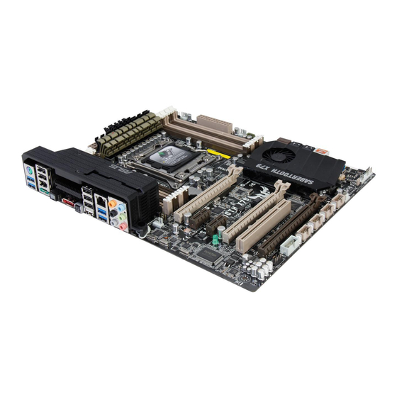
Page 20: Motherboard Overview
Motherboard overview 2.2.1 Motherboard layout Refer to 2.2.8 Internal connectors and 2.3.11 Rear panel connection for more information about rear panel connectors and internal connectors. Chapter 2: Hardware information... -
Page 21: Layout Contents
USB 2.0 connectors (10-1 pin USB78, USB910, USB1112, 2-21 USB1314) Serial port connector (10-1 pin COM1) 2-20 Front panel audio connector (10-1 pin AAFP) 2-23 Digital audio connector (4-1 pin SPDIF_OUT) 2-21 Standby power LED (SB_PWR) 2-16 ASUS SABERTOOTH X79... -
Page 22: Central Processing Unit (Cpu)
Contact your retailer immediately if the PnP cap is missing, or if you see any damage to the PnP cap/socket contacts/motherboard components. ASUS will shoulder the cost of repair only if the damage is shipment/ transit-related. -
Page 23: System Memory
The motherboard comes with eight Double Data Rate 3 (DDR3) Dual Inline Memory Modules (DIMM) slots. A DDR3 module is notched differently from a DDR or DDR2 module. DO NOT install a DDR or DDR2 memory module to the DDR3 slot. Recommended memory configurations ASUS SABERTOOTH X79... -
Page 24: Memory Configurations
• The Max. 64GB memory capacity can be supported with DIMMs of 8GB (or above). ASUS will update QVL once the DIMMs are available on the market. • According to Intel CPU spec, DIMM voltage below 1.65V is recommended to protect the CPU. - Page 25 DS NANYA NT5CB256M8GN-CG • • • • OCZ3P1333LV3GK 3GB(3x1GB) 7-7-7 1.65 • • • OCZ3G1333LV4GK 4GB(2x2GB) DS - 9-9-9 1.65 • • OCZ3P1333LV4GK 4GB(2x2GB) DS - 7-7-7 1.65 • • OCZ3G1333LV8GK 8GB(2x4GB) DS - 9-9-9 1.65 • ASUS SABERTOOTH X79...
- Page 26 SABERTOOTH X79 Motherboard Qualified Vendors Lists (QVL) DDR3 1333 MHz capability (continued) DIMM socket support (Optional) Vendors Part No. Size Chip Brand Chip NO. Timing Voltage 2 DIMM 4 DIMM 6 DIMM 8 DIMM OCZ3G1333LV8GK 8GB(2x4GB) DS - 9-9-9 1.65 •...
- Page 27 1.65 • • • OCZ3X1600LV6GK(XMP) 6GB(3x2GB) 8-8-8 1.65 • • • Super Talent WP160UX4G9(XMP) 4GB(2x2GB) • • Super Talent WB160UX6G8(XMP) 6GB(3x2GB) • • Super Talent WB160UX6G8(XMP) 6GB(3x2GB) • • Asint SLZ3128M8-EGJ1D(XMP) Asint 3128M8-GJ1D - • • • ASUS SABERTOOTH X79...
- Page 28 SABERTOOTH X79 Motherboard Qualified Vendors Lists (QVL) DDR3 1600 MHz capability (continued) DIMM socket support (Optional) Chip Vendors Part No. Size Chip NO. Timing Voltage Brand 2 DIMM 4 DIMM 6 DIMM 8 DIMM EK Memory EKM324L28BP8-I16(XMP) 4GB(2x2GB) • EK Memory EKM324L28BP8-I16(XMP) 4GB(2x2GB) •...
- Page 29 • G.SKILL F3-19200CL9D-4GBPIS(XMP) 4G(2x2G) 9-11-9-28 1.65 • • GEIL GET34GB2400C9DC(XMP) 4GB(2x2GB) DS 9-11-9-27 1.65 • • Transcend TX2400KLU-4GK (381850)(XMP) 2GB 1.65 • • Transcend TX2400KLU-4GK(374243)(XMP) 1.65 • • Patriot PVV34G2400C9K(XMP) 4GB(2x2GB) DS 9-11-9-27 1.66 • • ASUS SABERTOOTH X79 2-11...
-
Page 30: Expansion Slots
2.2.4 Expansion slots Ensure to unplug the power cord before adding or removing expansion cards. Failure to do so may cause you physical injury and damage motherboard components. Slot No. Slot Description PCIe 3.0 x16_1 slot (single at x16 or dual at x16/x16 mode) PCIe 2.0 x1_1 slot PCIe 2.0 x1_2 slot PCIe 3.0 x16_2 slot (single at x16 or dual at x16 / x16 mode) - Page 31 – – – shared – On Chip SATA – – – – shared – – – IEEE 1394 – shared – – – – – – PCI slot shared – – – – – – – ASUS SABERTOOTH X79 2-13...
-
Page 32: Jumper
2.2.5 Jumper Clear RTC RAM (3-pin CLRTC) This jumper allows you to clear the Real Time Clock (RTC) RAM in CMOS. You can clear the CMOS memory of date, time, and system setup parameters by erasing the CMOS RTC RAM data. -
Page 33: Onboard Switch
BIOS default settings. A messgae will appear during POST reminding you that the BIOS has been restored to its default settings. • We recommend that you download and update to the latest BIOS version from the ASUS website at www.asus.com after using the MemOK! function. ASUS SABERTOOTH X79 2-15... -
Page 34: Onboard Leds
2.2.7 Onboard LEDs Standby Power LED The motherboard comes with a standby power LED. The green LED lights up to indicate that the system is ON, in sleep mode, or in soft-off mode. This is a reminder that you should shut down the system and unplug the power cable before removing or plugging in any motherboard component. -
Page 35: Internal Connectors
Windows 7 or Vista installation for the system to detect the optical disk drive (ODD), or else the ODD will not run. We strongly recommend that you copy the IRST Driver from the support CD to the USB flash drive before OS installation. ASUS SABERTOOTH X79 2-17... - Page 36 ® Intel X79 Serial ATA 3Gb/s connectors (7-pin SATA3G_3–6 [black]) These connectors connect to Serial ATA 3Gb/s hard disk drives and optical disc drives via Serial ATA 3Gb/s signal cables. If you installed Serial ATA hard disk drives, you can create a RAID 0, 1, 5, and 10 ®...
- Page 37 • You must install Windows XP Service Pack 3 or later versions before using Serial ATA hard disk drives. • For high performance of ASUS SSD Caching, please connect one HDD and one SSD to Marvell ® SATA6G_E1/E2 connectors. •...
- Page 38 Serial port connector (10-1 pin COM1) This connector is for a serial (COM) port. Connect the serial port module cable to this connector, then install the module to a slot opening at the back of the system chassis. The COM module is purchased separately. USB 3.0 connector (20-1 pin USB3_56) This connector is for the additional USB 3.0 ports, and complies with the USB 3.0 specificaton that supports up to 5 Gbps connection speed.
- Page 39 Never connect a 1394 cable to the USB connectors. Doing so will damage the motherboard! You can connect the front panel USB cable to the ASUS Q-Connector (USB, blue) first, and then install the Q-Connector (USB) to the USB connector onboard if your chassis supports front panel USB ports.
- Page 40 CPU, chassis, and assistant fan connectors (4-pin CPU_FAN; 4-pin CPU_OPT FAN; 4-pin CHA_FAN1-4; 4-pin ASST_FAN) Connect the fan cables to the fan connectors on the motherboard, ensuring that the black wire of each cable matches the ground pin of the connector. Do not forget to connect the fan cables to the fan connectors.
- Page 41 Front Panel Type item in the BIOS setup to [HD]; if you want to connect an AC'97 front panel audio module to this connector, set the item to [AC97]. By default, this connector is set to [HD]. ASUS SABERTOOTH X79 2-23...
- Page 42 1000W power or above to ensure the system stability. • If you are uncertain about the minimum power supply requirement for your system, refer to the Recommended Power Supply Wattage Calculator at http://support.asus. com/PowerSupplyCalculator/PSCalculator.aspx?SLanguage=en-us for details. 2-24 Chapter 2: Hardware information...
-
Page 43: System Panel Connector
Pressing the power switch for more than four seconds while the system is ON turns the system OFF. • Reset button (2-pin RESET) This 2-pin connector is for the chassis-mounted reset button for system reboot without turning off the system power. ASUS SABERTOOTH X79 2-25... -
Page 44: Building Your Computer System
Building your computer system 2.3.1 Additional tools and components to build a PC system 1 bag of screws Philips (cross) screwdriver PC chassis Power supply unit Intel LGA 2011 CPU Intel LGA 2011 compatible CPU Fan DIMM SATA hard disk drive SATA optical disc drive (optional) Graphics card (optional) The tools and components in the table above are not included in the motherboard package. -
Page 45: Cpu Installation
Please note the order in opening/ closing the double latch. Follow the instructions printed on the metal sealing hatch or the illustrations shown below in this manual. The plastic cap will pop up automatically once the CPU is in place and the hatch properly sealed down. Load lever ASUS SABERTOOTH X79 2-27... - Page 46 2-28 Chapter 2: Hardware information...
-
Page 47: Cpu Heatsink And Fan Assembly Installation
2.3.3 CPU heatsink and fan assembly installation Apply the Thermal Interface Material to the CPU heatsink and CPU before you install the heatsink and fan if necessary. To install the CPU heatsink and fan assembly ASUS SABERTOOTH X79 2-29... -
Page 48: Dimm Installation
2.3.4 DIMM installation To remove a DIMM 2-30 Chapter 2: Hardware information... -
Page 49: Motherboard Installation
2.3.5 Motherboard installation The diagrams in this section are for reference only. The motherboard layout may vary with models, but the installation steps remain the same. ASUS SABERTOOTH X79 2-31... - Page 50 DO NOT overtighten the screws! Doing so can damage the motherboard. 2-32 Chapter 2: Hardware information...
-
Page 51: Thermal Armor For Asus Sabertooth X79
2.3.6 Thermal Armor for ASUS SABERTOOTH X79 The Thermal Armor for ASUS SABERTOOTH X79 consists of a rear I/O cover and a PCH cover and fan assembly, providing effective dissipation of the heat generated from the motherboard components. To ensure the most optimum heat dissipation, follow the instruction below to install the I/O cover fan to the rear I/O cover. - Page 52 If the PCH fan is not working or the fan speed is too slow, check if the fan cable is well-connected. If the problem persists, refer to local ASUS service centers for help. 2-34 Chapter 2: Hardware information...
-
Page 53: Atx Power Connection
2.3.7 ATX Power connection ASUS SABERTOOTH X79 2-35... -
Page 54: Sata Device Connection
2.3.8 SATA device connection 2-36 Chapter 2: Hardware information... -
Page 55: Front I/O Connector
2.3.9 Front I/O Connector To install ASUS Q-Connector To install USB 2.0 Connector To install front panel audio connector AAFP USB 2.0 To install USB 3.0 Connector USB 3.0 ASUS SABERTOOTH X79 2-37... -
Page 56: Expension Card Installation
2.3.10 Expension Card installation To install PCIe x16 cards To install PCIe x1 cards To install PCI cards 2-38 Chapter 2: Hardware information... -
Page 57: Rear Panel Connection
5. USB 3.0 ports 3 and 4 11. USB 3.0 ports 1 and 2 6. Power eSATA 6G port 12. Audio I/O ports** * and **: Refer to the tables on the next page for LAN port LED and audio port definitions. ASUS SABERTOOTH X79 2-39... - Page 58 • DO NOT insert a different connector to the external SATA port. ® • DO NOT connect a keyboard/mouse to any USB 3.0 port when installing Windows operating system. • Due to USB 3.0 controller limitation, USB 3.0 devices can only be used under ®...
-
Page 59: Audio I/O Connections
2.3.12 Audio I/O connections Audio I/O ports Connect to Headphone and Mic Connect to Stereo Speakers Connect to 2.1 channel Speakers ASUS SABERTOOTH X79 2-41... - Page 60 Connect to 4.1 channel Speakers Connect to 5.1 channel Speakers Connect to 7.1 channel Speakers 2-42 Chapter 2: Hardware information...
-
Page 61: Usb Bios Flashback
2.3.13 USB BIOS Flashback Download the BIOS ROM file from the ASUS service website (www.asus.com) and rename the ROM file to SABERX79.ROM. Save the ROM file to a USB portable disk. On the rear I/O port, plug the USB disk to the USB port with the WHITE interior. (See... -
Page 62: Starting Up For The First Time
Starting up for the first time After making all the connections, replace the system case cover. Be sure that all switches are off. Connect the power cord to the power connector at the back of the system chassis. Connect the power cord to a power outlet that is equipped with a surge protector. Turn on the devices in the following order: Monitor External SCSI devices (starting with the last device on the chain) -
Page 63: Chapter 3: Bios Setup
BIOS setup Knowing BIOS The new ASUS UEFI BIOS is an Unified Extensible Firmware Interface that complies with UEFI architecture, offering a user-friendly interface that goes beyond traditional keyboard- only BIOS controls to enable more flexible and convenient mouse input. Users can easily navigate the new UEFI BIOS with the same smoothness as their operating system. -
Page 64: Ez Mode
Quick switch to frequently Loads optimized default Power Saving mode used menus. Normal mode ASUS Optimal mode Selects the boot device priority Selects the boot device priority Displays the system properties of the selected mode on the right hand side •... -
Page 65: Advanced Mode
The Advanced Mode provides advanced options for experienced end-users to configure the BIOS settings. The figure below shows an example of the Advanced Mode. Refer to the following sections for the detailed configurations. To access the EZ Mode, click Exit, then select ASUS EZ Mode. Menu items Menu bar... -
Page 66: Menu Items
Menu items The highlighted item on the menu bar displays the specific items for that menu. For example, selecting Main shows the Main menu items. The other items (Ai Tweaker, Advanced, Monitor, Boot, Tool, and Exit) on the menu bar have their respective menu items. -
Page 67: Main Menu
RAM to clear the BIOS password. See section 2.2.5 Jumper for information on how to erase the RTC RAM. • The Administrator or User Password items on top of the screen show the default Not Installed. After you set a password, these items show Installed. ASUS SABERTOOTH X79... -
Page 68: Administrator Password
Administrator Password If you have set an administrator password, we recommend that you enter the administrator password for accessing the system. Otherwise, you might be able to see or change only selected fields in the BIOS setup program. To set an administrator password: Select the Administrator Password item and press <Enter>. -
Page 69: Ai Tweaker Menu
Use the <+> and <-> keys to adjust the value. You can also key in the desired value using the numeric keypad. The values range from 80.0MHz to 300.0MHz. CPU Strap [Auto] Configuration options: [Auto] [100MHz] [125MHz] [166MHz] [250MHz] ASUS SABERTOOTH X79... - Page 70 ClockGen Full Reset [Enabled] [Enabled] Enabled for better overclocking. [Disabled] To skip system shutdown at BCLK frequency adjustment. Turbo Ratio [Auto] Allows you to manually adjust the Trubo CPU ratio. [Auto] All Turbo ratio are set by Intel CPU default settings. [By ALL Cores (Can Adjust in OS)] All numbers of active cores will be set to one single Turbo ratio in OS.
-
Page 71: Dram Timing Control
Configuration options: [Auto] [1 DRAM Clock] [2 DRAM Clock] [3 DRAM Clock] Secondary Timings DRAM RAS# to RAS# Delay [Auto] Configuration options: [Auto] [4 DRAM Clock] – [7 DRAM Clock] DRAM REF Cycle Time [Auto] Configuration options: [Auto] [48 DRAM Clock] – [511 DRAM Clock] ASUS SABERTOOTH X79... - Page 72 DRAM WRITE Recovery Time [Auto] Configuration options: [Auto] [5 DRAM Clock] – [31 DRAM Clock] DRAM READ to PRE Time [Auto] Configuration options: [Auto] [4 DRAM Clock] – [15 DRAM Clock] DRAM FOUR ACT WIN Time [Auto] Configuration options: [Auto] [16 DRAM Clock] – [63 DRAM Clock] DRAM WRITE to READ Delay [Auto] Configuration options: [Auto] [4 DRAM Clock] –...
- Page 73 CPU and VRM thermal. This item allows you to adjust the voltage range from the following percentages to boost the system performance: 0% (Regular), 25% (Medium), 50% (High), 75% (Ultra High) and 100% (Extreme). Configuration options: [Auto] [Regular] [Medium] [High] [Ultra High] [Extreme] ASUS SABERTOOTH X79 3-11...
- Page 74 [Auto] Loads the settings for the system automatically. [Standard] Proceeds phase control depending on the CPU loading. [Optimized] Loads the ASUS optimized phase tuning profile. [Extreme] Proceeds the full phase mode. [Manual Adjustment] Allows manual adjustment for Regular/Medium/Fast/Ultra Fast options.
- Page 75 [manual] and allows you to set a DRAM fixed frequency. The values range from 300kHz to 500kHz with a 50kHz interval. DRAM-AB/DRAM-CD Power Phase control [Auto] [Optimized] Allows you to set ASUS optimized phase tuning profile. [Extreme] Allows you to set the Full phase mode. [Auto] Automatic configuration.
- Page 76 Power Limit 1. Default setting is 1.25 times Power Limit 1. For Intel recommend, platform must be capable of supporting over Power Limit 2 for up to 10 msec. ASUS board can support over Power Limit 2 for a long duration. Use the <+> and <-> keys to adjust the value.
- Page 77 CPU permanently. We recommend you install the DIMMs with the voltage requirement below 1.65V. CPU PLL Voltage [Auto] Allows you to set the CPU and PCH PLL voltage. The values range from 1.80V to 2.10V with a 0.00625V interval. ASUS SABERTOOTH X79 3-15...
- Page 78 VTTCPU Voltage [Auto] Allows you to set the VTTCPU voltage. The values range from 1.05V to 1.70V with a 0.00625V interval. PCH 1.1v Voltage [Auto] Allows you to set the 1.1v Platform Controller Hub voltage. The values range from 1.10V to 1.70V with a 0.00625V interval.
-
Page 79: Advanced Menu
The Advanced menu items allow you to change the settings for the CPU and other system devices. Be cautious when changing the settings of the Advanced menu items. Incorrect field values can cause the system to malfunction. ASUS SABERTOOTH X79 3-17... -
Page 80: Cpu Configuration
3.5.1 CPU Configuration The items in this menu show the CPU-related information that the BIOS automatically detects. The items shown in this screen may be different due to the CPU you installed. Intel Adaptive Thermal Monitor [Enabled] [Disabled] Disables the CPU thermal monitor function. [Enabled] Enables the overheated CPU to throttle its clock speed to cool down. - Page 81 [Auto] Loads the settings automatically. CPU C7 Report [Auto] Allows you to disable or enable the CPU C7 report to OS. [Auto] Loads the settings automatically. [Enabled] Enables the C7 Report function. [Disabled] Disables this function. ASUS SABERTOOTH X79 3-19...
-
Page 82: Pch Configuration
3.5.2 PCH Configuration High Precision Timer [Enabled] Allows you to enable or disable the High Precision Event Timer. Configuration options: [Disabled] [Enabled] 3.5.3 SATA Configuration While entering Setup, the BIOS automatically detects the presence of SATA devices. The SATA Port items show Not Present if no SATA device is installed to the corresponding SATA port. SATA Mode [AHCI Mode] Allows you to set the SATA configuration. - Page 83 POST. Configuration options: [Enabled] [Disabled] Hot Plug [Disabled] These items appear only when you set the SATA Mode item to [AHCI Mode] or [RAID Mode] and allow you to enable/disable SATA Hot Plug Support. Configuration options: [Disabled] [Enabled]. ASUS SABERTOOTH X79 3-21...
-
Page 84: Usb Configuration
3.5.4 USB Configuration The items in this menu allow you to change the USB-related features. The USB Devices item shows the auto-detected values. If no USB device is detected, the item shows None. Legacy USB Support [Enabled] [Disabled] The USB devices can be used only for the BIOS setup program. [Enabled] Enables the support for USB devices on legacy operating systems (OS). -
Page 85: Onboard Devices Configuraton
Enables the Intel LAN controller. Intel PXE OPROM [Disabled] This item appears only when you set the previous item to [Enabled] and allows you to enable or disable the PXE OptionRom of the Intel LAN controller. Configuration options: [Enabled] [Disabled] ASUS SABERTOOTH X79 3-23... - Page 86 VIA 1394 Controller [Enabled] This item allows user to enabled/disabled VIA 1394 controller. Configuration options: [Disabled] [Enabled] PCI Express x1_1 Slot Configuration [Auto] [AUTO] The system auto-detects the occupied PCIEx1_1 slot or SATA6G_E1/E2 connector. When both are occupied, only PCIEx1_1 slot can work. [SATA6G_E1/E2] If SATA6G_E1/E2 (Marvell controller) is enabled, PCIEx1_1 slot will be blocked and you can connect devices to the SATA6G_E1/E2 connector.
-
Page 87: Apm
ErP Ready [Disabled] This item allows user to switch off some power at S5 to get the system ready for ErP requirement. When set to Enabled, all other PME options will be switched off. Configuration options: [Disabled] [Enabled] ASUS SABERTOOTH X79 3-25... -
Page 88: Monitor Menu
Monitor menu The Monitor menu displays the system temperature/power status, and allows you to change the fan settings. CPU Temperature / MB Temperature [xxxºC/xxxºF] The onboard hardware monitor automatically detects and displays the CPU and motherboard temperatures. Select Ignore if you do not wish to display the detected temperatures. CPU Fan Speed;... - Page 89 [Silent] Sets to [Silent] to minimize the fan speed for quiet chassis fan operation. [Turbo] Sets to [Turbo] to achieve maximum chassis fan speed. [Manual] Sets to [Manual] to assign detailed fan speed control parameters. ASUS SABERTOOTH X79 3-27...
- Page 90 The following four items appear only when you set Chassis 1/2/3/4 Fan Profile to [Manual]. Chassis 1/2/3/4 Upper Temperature [70] Use the <+> and <-> keys to adjust the upper limit of the chassis temperature. The values range from 40ºC to 90ºC. Chassis 1/2/3/4 Fan Max.
- Page 91 The onboard hardware monitor automatically detects the voltage output through the onboard voltage regulators. Select Ignore if you do not want to detect this item. Anti Surge Support [Enabled] This item allows you to enable or disable the Anti Surge function. Configuration options: [Disabled] [Enabled] ASUS SABERTOOTH X79 3-29...
-
Page 92: Boot Menu
Full Screen Logo [Enabled] [Enabled] Enables the full screen logo display feature. [Disabled] Disables the full screen logo display feature. Set this item to [Enabled] to use the ASUS MyLogo 2™ feature. Wait For ‘F1’ If Error [Enabled] [Disabled] Disables this function. [Enabled] The system waits for the <F1>... -
Page 93: Boot Option Priorities
• To select the boot device during system startup, press <F8> when ASUS Logo appears. • To access Windows OS in Safe Mode, press <F8> after POST. -
Page 94: Tool Menu
3.8.1 ASUS EZ Flash 2 Utility Allows you to run ASUS EZ Flash 2 Utility. When you press <Enter>, a confirmation message appears. Use the left/right arrow key to select between [Yes] or [No], then press <Enter> to confirm your choice. -
Page 95: Asus Dram Spd Information
3.8.2 ASUS DRAM SPD Information This menu showed the DIMM slot related informatons. ASUS SABERTOOTH X79 3-33... -
Page 96: Asus O.c. Profile
3.8.3 ASUS O.C. Profile This item allows you to store or load multiple BIOS settings. The Setup Profile Status items show Not Installed if no profile is created. Label Allows you to input the label of setup profile. Save to Profile Allows you to save the current BIOS settings to the BIOS Flash, and create a profile. -
Page 97: Asus Drive Xpert
3.8.4 ASUS Drive Xpert • Before using the Drive Xpert function, ensure that you have connected the SATA signal cables and installed SATA hard disk drives to the SATA6G_E1 and SATA6G_E2 connectors. • You can only make one Drive Xpert change a time before you save BIOS settings and restart the computer. -
Page 98: Exit Menu
Load Optimized Defaults Save Changes & Reset Discard Changes & Exit ASUS EZ Mode Launch UEFI Shell from filesystem device Load Optimized Defaults This option allows you to load the default values for each of the parameters on the Setup menus. -
Page 99: Updating Bios
BIOS in the future. Copy the original motherboard BIOS using the ASUS Update or BIOS Updater utilities. 3.10.1 ASUS Update utility The ASUS Update is a utility that allows you to manage, save, and update the motherboard BIOS in Windows environment. The ASUS Update utility allows you to: ®... - Page 100 To update the BIOS through the Internet: From the ASUS Update screen, select Update BIOS from Internet, and then click Next. Select the ASUS FTP site nearest you to avoid network traffic. If you want to enable the BIOS downgradable function and auto...
- Page 101 The screenshots in this section are for reference only. The actual BIOS information vary by models. • Refer to the software manual in the support DVD or visit the ASUS website at www.asus.com for detailed software configuration. ASUS SABERTOOTH X79...
-
Page 102: Asus Ez Flash 2 Utility
3.10.2 ASUS EZ Flash 2 utility The ASUS EZ Flash 2 feature allows you to update the BIOS without having to use a bootable floppy disk or an OS-based utility. Before you start using this utility, download the latest BIOS from the ASUS website at www.asus.com. -
Page 103: Asus Crashfree Bios 3 Utility
The BIOS file in the motherboard support DVD may be older than the BIOS file published on the ASUS official website. If you want to use the newer BIOS file, download the file at support.asus.com and save it to a USB flash drive. -
Page 104: Asus Bios Updater
3.10.4 ASUS BIOS Updater The ASUS BIOS Updater allows you to update BIOS in DOS environment. This utility also allows you to copy the current BIOS file that you can use as a backup when the BIOS fails or gets corrupted during the updating process. - Page 105 ASUSTek BIOS Updater for DOS V1.18 [2011/04/29] Current ROM Update ROM BOARD: SABERTOOTH X79 BOARD: Unknown VER: 0401 VER: Unknown DATE: 09/16/2011 DATE: Unknown PATH: BIOS backup is done! Press any key to continue. Note Saving BIOS: ASUS SABERTOOTH X79 3-43...
- Page 106 Updating the BIOS file To update the BIOS file using BIOS Updater At the FreeDOS prompt, type bupdater /pc /g and press <Enter>. D:\>bupdater /pc /g The BIOS Updater screen appears as below. ASUSTek BIOS Updater for DOS V1.18 [2011/04/29] Current ROM Update ROM BOARD:...
-
Page 107: Chapter 4: Software Support
The contents of the support DVD are subject to change at any time without notice. Visit the ASUS website at www.asus.com for updates. 4.2.1 Running the support DVD Place the support DVD into the optical drive. -
Page 108: Obtaining The Software Manuals
® Acrobat Reader from the Utilities menu before opening the files. ® Click on the Manual tab. Click on ASUS Motherboard Utility Guide from the manual list on the left. The Manual folder of the support DVD appears. Double-click the folder of your selected software. -
Page 109: Software Information
4.3.1 AI Suite II AI Suite II is an all-in-one interface that integrates several ASUS utilities and allows users to launch and operate these utilities simultaneously. Installing AI Suite II To install AI Suite II on your computer Place the support DVD to the optical drive. -
Page 110: Asus Tuf Thermal Radar
4.3.2 ASUS TUF Thermal Radar The TUF Thermal Radar monitors temps in critical parts of the motherboard in real time, automatically adjusting fan speeds to make sure the system maintains high stability without overheating. It consists of multiple sensors for various components on the motherboard, giving user the ability to monitor each one individually. - Page 111 Read the introduction and notice of the selected fan. Click Setting. Select a fan profile in the Profile Name drop-down list and click Apply. You can also configure other system fans by clicking the CHA and ASST icon below. ASUS SABERTOOTH X79...
- Page 112 Configuring user-customizable fan settings You can customize the fan speed to meet different computing and environment needs. To fast customize the fan speed Select User in the Profile Name drop- down list. Drag the control points on the fan speed curve to set the fan speed percentage.
- Page 113 If you are not sure how to choose the proper components to monitor and the percentage to adjust, click Auto and have Thermal Radar do the recommended settings for you. Click Apply for the setting to take effect. ASUS SABERTOOTH X79...
-
Page 114: Turbov Evo
After installing AI Suite II from the motherboard support DVD, launch TurboV EVO by clicking Tool > TurboV EVO on the AI Suite II main menu bar. Refer to the software manual in the support DVD or visit the ASUS website at www.asus.com for detailed software configuration. - Page 115 Set the CPU Ratio Setting item in BIOS to [Auto] before using the CPU Ratio function • in TurboV. Refer to Chapter 3 of your motherboard user manual for details. • The CPU Ratio bars show the status of the CPU cores, which vary with your CPU model. ASUS SABERTOOTH X79...
- Page 116 CPU Strap Allows you to manually adjust CPU Strap. Click the CPU Strap tab. Drag the adjustment bar to the desired value. The graph on the right will change value accordingly. Click Apply and reboot the system to make the change take effect. CPU Strap Adjustment bar Undoes all changes...
-
Page 117: Digi+ Power Control
Reduce phase number under light system loading to increase VRM efficiency. CPU Power Duty Control CPU Power Duty Control adjusts the current of every VRM phase and the thermal of every phase component. ASUS SABERTOOTH X79 4-11... - Page 118 OC Range. DRAM Power Phase Control Select Extreme for full phase mode to increase system performance. Select Optimized for ASUS optimized phase tuning profile to increase DRAM power efficiency. • The actual performance boost may vary depending on your CPU and DRAM specification.
-
Page 119: Sensor Recorder
To stop the recording process, click Recording again. To track the recording details, select Date/Type/Select display items. Click on Monitor > Sensor on the AI Suite II main menu bar and a highlight of the system statuses will appear on the right panel. ASUS SABERTOOTH X79 4-13... -
Page 120: Usb 3.0 Boost
4.3.6 USB 3.0 Boost The ASUS exclusive USB 3.0 Boost provides speed boost for USB 3.0 devices and the up-to-date support of USB Attached SCSI Protocol (UASP). With USB 3.0 Boost, you can accelerate the transfer speed of your USB 3.0 devices with ease. -
Page 121: Asus Ssd Caching
Launching ASUS SSD Caching After installing AI Suite II from the motherboard support DVD, launch ASUS SSD Caching by clicking Tool > ASUS SSD Caching on the AI Suite II main menu bar. Configuring ASUS SSD Caching Connect one HDD and one SSD to the... -
Page 122: Asus Update
4.3.8 ASUS Update ASUS Update lays out the options for updating BIOS on your system. Update BIOS utility on your system or simply save the utility for later use just by following the directions on this convenient updating feature. Launching ASUS Update After installing AI Suite II from the motherboard support DVD, launch ASUS Update by clicking Update>... -
Page 123: Mylogo2
Power-On-Self-Tests (POST). Personalize your computer from the very beginning! Launching ASUS Update After installing AI Suite II from the motherboard support DVD, launch MyLogo by clicking Update> MyLogo on the AI Suite II main menu bar. - Page 124 Click on Auto Tune to adjust image size compatibility or adjust the resolution bar. You can click on Booting Preview to preview the boot image. Then click Next. Click on Flash to start updating the image to the boot logo. Click on Yes to reboot or you can also see the new logo next time you restart your computer.
-
Page 125: Audio Configurations
Realtek HD Audio Manager for Windows XP Exit button Configuration options Minimize button Control settings window Information button Refer to the software manual in the support DVD or visit the ASUS website at www.asus.com for detailed software configuration. ASUS SABERTOOTH X79 4-19... -
Page 126: Raid Configurations
RAID configurations The motherboard comes with the Intel X79 chipset and Marvell SATA controller that allow ® you to configure Serial ATA hard disk drives as RAID sets. The motherboard supports the following RAID configurations: Intel Rapid Storage Technology with RAID 0, RAID 1, RAID 10 and RAID 5 support. •... -
Page 127: Installing Serial Ata Hard Disks
None defined. Physical Devices: Port Device Model Serial # Size Type/Status(Vol ID) ST3160812AS 9LS0HJA4 149.0GB Non-RAID Disk ST3160812AS 9LS0F4HL 149.0GB Non-RAID Disk ST3160812AS 3LS0JYL8 149.0GB Non-RAID Disk ST3160812AS 9LS0BJ5H 149.0GB Non-RAID Disk [↑↓]-Select [ESC]-Exit [ENTER]-Select Menu ASUS SABERTOOTH X79 4-21... -
Page 128: Creating A Raid Set
The navigation keys at the bottom of the screen allow you to move through the menus and select the menu options. The RAID BIOS setup screens shown in this section are for reference only and may not exactly match the items on your screen. The utility supports maximum four hard disk drives for RAID configuration. - Page 129 WARNING: ALL DATA ON SELECTED DISKS WILL BE LOST. Are you sure you want to create this volume? (Y/N): Press <Y> to create the RAID volume and return to the main menu, or <N> to go back to the CREATE VOLUME menu. ASUS SABERTOOTH X79 4-23...
- Page 130 Deleting a RAID set Take caution when deleting a RAID set. You will lose all data on the hard disk drives when you delete a RAID set. To delete a RAID set: From the utility main menu, select 2. Delete RAID Volume and press <Enter>. The following screen appears: Intel(R) Rapid Storage Technology - Option ROM - v10.0.0.1032 Copyright(C) 2003-10 Intel Corporation.
-
Page 131: Marvell Raid Utility
Press <Space> to select the hard drives to be included in the RAID array. An asterisk (*) appears in front of the selected hard drive. After selecting all the drives needed for the RAID array, press <Enter> to continue. ASUS SABERTOOTH X79 4-25... - Page 132 Marvell BIOS Setup (c) 2009 Marvell Technology Group Ltd. Configure->Select free disksCreate Virtual Disk HBA 0: Marvell 0 RAID Level : RAID 0 Virtual Disks Max Size(MB) : 305253 ├ Free Physical Disks Stripe Size : 64KB └ ├ PD 0: ST3160812AS Gigabyte Rounding : 1G └...
- Page 133 Stripte Size │ └ PD 8: ST3160812AS RAID Mode RAID0 │ └ Free Physical Disks Size 304128MB BGA Status Number of PDs Members ▶ ▶ Help Delete the selected virtual disk. ENTER: Operation F10: Exit/Save ESC: Return ASUS SABERTOOTH X79 4-27...
- Page 134 The following warning message appears: Delete Virtual Disk Do you want to delete this virtual disk ? Press <Y> to delete the selected RAID array. The following warning message appears: Delete MBR Do you want to delete MBR from this virtual disk ? Press <Y>...
-
Page 135: Creating A Raid Driver Disk
Go to the Make Disk menu, and then click Intel AHCI/RAID Driver Disk to create a RAID driver disk. Select USB floppy disk drive as the destination disk. Follow the succeeding screen instructions to complete the process. Write-protect the floppy disk to avoid a computer virus infection. ASUS SABERTOOTH X79 4-29... -
Page 136: Installing The Raid Driver During Windows ® Os Installation
4.5.3 Installing the RAID driver during Windows OS installation ® To install the RAID driver in Windows ® During the OS installation, the system prompts you to press the F6 key to install third- party SCSI or RAID driver. Press <F6>, and then insert the floppy disk with RAID driver into the USB floppy disk drive. When prompted to select the SCSI adapter to install, select the RAID driver for the corresponding OS version. -
Page 137: Using A Usb Floppy Disk Drive
Product ID (PID) are displayed. Browse the contents of the RAID driver disk to locate the file txtsetup.oem. Double-click the file. A window appears, allowing you to select the program for opening the oem file. ASUS SABERTOOTH X79 4-31... - Page 138 Use Notepad to open the file. Find the [HardwareIds.scsi.iaAHCI_DesktopWorkstationServer] and [HardwareIds.scsi.iaStor_DesktopWorkstationServer] sections in the txtsetup.oem file. Type the following line to the bottom of the two sections: id = “USB\VID_xxxx&PID_xxxx”, “usbstor” [HardwareIds.scsi.iaAHCI_DesktopWorkstationServer] id= “PCI\VEN_8086&DEV_1C02&CC_0106”,”iaStor” id= “USB\VID_03EE&PID_6901”, “usbstor” [HardwareIds.scsi.iaStor_DesktopWorkstationServer] id= “PCI\VEN_8086&DEV_2822&CC_0104”,”iaStor” id= “USB\VID_03EE&PID_6901”, “usbstor”...
-
Page 139: Chapter 5: Multiple Gpu Technology Support
For Windows XP, go to Control Panel > Add/Remove Programs. For Windows Vista, go to Control Panel > Programs and Features. Select your current graphics card driver/s. For Windows XP, select Add/Remove. For Windows Vista, select Uninstall. Turn off your computer. ASUS SABERTOOTH X79... -
Page 140: Installing Two Crossfirex™ Graphics Cards
5.1.3 Installing two CrossFireX™ graphics cards The following pictures are for reference only. The graphics cards and the motherboard layout may vary with models, but the installation steps remain the same. Prepare two CrossFireX-ready graphics cards. Insert the two graphics card into the PCIEX16 slots. -
Page 141: Installing The Device Drivers
Graphics Settings > Performance > AMD CrossFireX Configuration. From the Graphics Adapter list, select the graphics card to act as the display GPU. Select Enable CrossFireX Click Apply, and then click OK to exit the window. ASUS SABERTOOTH X79... -
Page 142: Nvidia ® Sli™ Technology
NVIDIA SLI™ technology ® The motherboard supports the NVIDIA SLI™ (Scalable Link Interface) technology that ® allows you to install multi-graphics processing units (GPU) graphics cards. Follow the installation procedures in this section. 5.2.1 Requirements • In SLI mode, you should have two identical SLI-ready graphics cards that are NVIDIA ®... -
Page 143: Installing The Device Drivers
You can launch the NVIDIA Control Panel by the following two methods. Right click on the empty space of the Windows desktop ® and select NVIDIA Control Panel. The NVIDIA Control Panel window appears (See Step B5). ASUS SABERTOOTH X79... - Page 144 If you cannot see the NVIDIA Control Panel item in step (A), select Personalize. From the Personalization window, select Display Settings. From the Display Settings dialog box, click Advanced Settings. Chapter 5: Multiple GPU technology support...
- Page 145 Start the NVIDIA Control Panel. The NVIDIA Control Panel window appears. Enabling SLI settings From the NVIDIA Control Panel window, select Set SLI Configuration. Click Enable SLI and set the display for viewing SLI rendered content. When done, click Apply. ASUS SABERTOOTH X79...
- Page 146 Chapter 5: Multiple GPU technology support...
-
Page 147: Asus Contact Information
+1-812-282-3777 +1-510-608-4555 Web site usa.asus.com Technical Support Telephone +1-812-282-2787 Support fax +1-812-284-0883 Online support support.asus.com ASUS COMPUTER GmbH (Germany and Austria) Address Harkort Str. 21-23, D-40880 Ratingen, Germany +49-2102-959911 Web site www.asus.de Online contact www.asus.de/sales Technical Support Telephone +49-1805-010923* Support Fax...
Need help?
Do you have a question about the SABERTOOTH X79 and is the answer not in the manual?
Questions and answers