Table of Contents
Advertisement
Quick Links
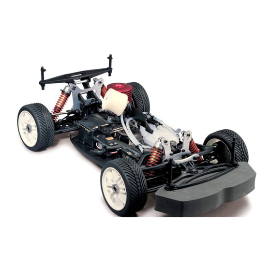
1/8th Nitro Powered 4WD Rally Car
No.6232-K10
Engine and electrics are not included in the kit.
◆
Please read all instructions thoroughly before assembling the kit.
The contents are subject to change without prior notice due to product improvements and specification changes.
Thunder Tiger Corporation guarantees this model kit to be free from defects in both material and workmanship. The
total monetary value under warranty will in no case exceed the cost of the original kit purchased. This warranty does
not cover any components damaged by use or modification. Part or parts missing from this kit must be reported
within 60 days of purchase. No part or parts will be sent under warranty without proof of purchase. To receive part
or parts under warranty, the service center must receive a proof of purchase and/or the defective part or parts. Should
you find a defective or missing part, contact the authorized Thunder Tiger Service/Distributor nearest you. Under no
circumstances can a dealer or distributor accept return of a kit if assembly has started.
Advertisement
Table of Contents

Related Manuals for THUNDER TIGER S3 EB 4 RALLY GAME


Summary of Contents for THUNDER TIGER S3 EB 4 RALLY GAME
- Page 1 The contents are subject to change without prior notice due to product improvements and specification changes. Thunder Tiger Corporation guarantees this model kit to be free from defects in both material and workmanship. The total monetary value under warranty will in no case exceed the cost of the original kit purchased. This warranty does not cover any components damaged by use or modification.
- Page 2 INTRODUCTION The Thunder Tiger EB-4 S3 was designed as a whole new off-road 4WD nitro-racing buggy, especially on a high-speed and bumpy off-road track. There's no doubt that the innovation would be the very first priority of our design team. We have set this buggy far ahead of the current form of existing buggy design in the market in terms of the future designing trend.
-
Page 3: Important Notes & Warning
3. If the fuel gets onto your skin, wash it well with soap and water. WARNING 1. Improper operations may cause personal and/or property damage. Thunder Tiger and its distributor have no control over damage resulting from shipping, improper construction, or improper usage. -
Page 4: Items Required For Assembly
ITEMS REQUIRED FOR ASSEMBLY Notice: The following items are required for completion of the EB-4 S3. Some of them are not included with this kit (unless noted), and should be obtained from the local hobby shop nearby you. (For separate purchasing products, please refer to Thunder Tiger professional R/C model products.) 1. - Page 5 STEERING SERVO SAVER Steering Bell-Crank Steering rod ø5x10mm Bearing Note Left thread, Right thread 20mm Inner Outer Servo tie rod PD1857 ALUM SERVO SAVER 13mm Ball joints must be 90˚ to each other...
- Page 6 3x16mm 3x16mm Note the direction of M3x16mm curve side Flat Head Hex Screw 3x20mm 3x16mm 3x20mm M3x20mm Flat Head Hex Screw Lock Nut, M3 M3x16mm Button Head Hex Screw 1.0mm Note the orientation. The small pivot balls are outside. 3x12mm M3x12mm Button Head Hex Screw Right...
- Page 7 GEAR DIFFERENTIALS Roll Pin, ø2.5x11mm O-ring, ø5.8x9.6mm O-ring, ø4.4x0.8mm 0.15mm Gear Shim Center diff out drive cup Hint: Use tweezer to insert pin PD1998 STEEL MAIN GEAR, 3x14mm 3x14mm Hint: Oil on the paper gasket will hold it in place M3x14mm Flat Head Hex Screw Fill the diff case with...
- Page 8 FRONT & REAR BULKHEADS Hint: Use supplied shims in bag B to adjust the proper gearmesh. Carefully when assembling, do not M3x22mm bend shims. Button Head Hex Screw 5x4mm From B bag M3x12mm Socket Head Hex Screw M3x16mm 3x22mm Socket Head Hex Screw 3x12mm Marked 3x16mm...
- Page 9 GEAR DIFFERENTIALS Marked "F" Temporarily insert M3x16mm brake disk here for Brake Pad Fixing Screw proper gap between pads. 3x16mm 3x16mm Marked "R" Note orientation PD1845 CTR DIFF MOUNT, S3 OPT I n s e r t b r a k e d i s k between brake Pads.
- Page 10 3x35mm 3x35mm M3x35mm Socket Head Hex Screw 3x3mm M3x3mm Set Screw...
- Page 11 CENTER DRIVE TRAIN Choose the FR0 toe block and RF2 toe block for the initial setting. You can adjust front caster, rear inboard toe and rear anti-squat by changing the different suspension M4x10mm arm holders to meet your race requirement. For more adjusting details, please refer Flat Head Hex Screw to "Set Up"...
-
Page 12: Front Suspension
FRONT SUSPENSION Front foam bumper not shown here. Marked "L" Roll Pin, ø3x17mm Note orientation M5x4mm Set Screw Marked "R" ø10x19mm Bearing Hint: Do not overtighten aluminum screws. Make them slightly touched, so ø8x16mm Bearing the pivot balls move freely. PD1860 HARD SWAY BAR PD1863 LITE PIVOT BALL, PD1864 LITE HEX WHL ADAPTER,... - Page 13 Maximun shim installation 5mm Marked "R" 1mm caster shim for spare use M3x30mm Button Head Hex Screw Marked "L" 3x10mm For alternative M3x10mm Button Head Hex Screw position. Please 1mm caster shim refer to P.29 Camber for spare use Adjustmet (Front) 3x30mm Check out non- binding movement...
-
Page 14: Rear Suspension
REAR SUSPENSION M3x12mm Set Screw Roll Pin, ø3x17mm 3x12mm M5x4mm Set Screw ø10x19mm Bearing Cut off shaded portion ø8x16mm Bearing 4x12mm 5x4mm M4x12mm Set Screw Cut off shaded portion 3x22mm Refer to P.30 for M3x22mm droop adjustment. Button Head Hex Screw 3.9mm Secure droop screw 3.9mm on the bottom... - Page 15 Tighten set screw onto the hinge pin flat spot. M3x5mm Wheelbase Set Screw adjustment spacers 3x5mm 3x5mm Note orientation Outer 40.8 mm Inner M4x12mm Flat Head Hex Screw PD1853 A7075 RR PLATE RR Insert the ball joints into TRANS, RR+2, S3 OPT the suspension holders.
- Page 16 Initial position on the rear shock tower Initial position on the rear hub M3x3mm Set Screw M3x5mm Set Screw M3x10mm Button Head Hex Screw PD1866 SWAY BAR,GOLD 3mm, 3x5mm PD1867 SWAY BAR, SILVER 3x10mm 2.5mm, S3 SIDE GUARD b ag 3x8mm Lock Nut, M3 M3x8mm...
- Page 17 RADIO BOX & FUEL TANK M3x8mm Apply few drops of CA glue around the profile Button Head Hex Screw edge of the carbon plate for added strength. 3x14mm M3x10mm 3x10mm Button Head Hex Screw M3x14mm 3x8mm Flat Head Socket Screw Hint: You can use servo grommets to protect your AD2523-R ANODIZED...
- Page 18 M3x10mm Button Head Hex Screw M3x10mm From F bag Flat Head Hex Screw 3x10mm 3x10mm M3x12mm Flat Head Hex Screw M3x22mm Button Head Hex Screw 3x22mm 3x12mm 3x12mm Hint: Cut the pressure nipple beneath the tank cap for fuel gun using. Hint: Cut a piece of fuel tubing as fuel tank grommet as shown.
- Page 19 ENGINE MOUNT & CLUTCH SET Engine rotation direction Note the orientation of the clutch shoes. M3x8mm Socket Head Hex Screw 3x8mm PD1980-1 CLUTCH SPRING, 0.9mm PD1980-2 CLUTCH SPRING, 1.1mm Approx. 1/8" Hint: The clutch tuning up is for PD0470 CLUTCH BELL 26mm,15T, 1/8 PD0619 CLUTCH BELL 26mm,14T, 1/8 Before Cutting After Cutting...
- Page 20 THROTTLE AND BRAKE LINKAGE 11.1 Cut the attached throttle rod M3x3mm in the bag (Approxi.15mm) to Set Screw avoid interfering. Cut off 15mm approx. Flat Washer, ø2.6 Cut excess off in order not to hit the tank. Install appropriat servo horn 11.2 accordingly to your servo.
- Page 21 1.Neutral 11.3 Throttle linkage adjustment Idle adjustment Screw Approx 0.5mm 2.High throttle Open fully 3.Brake Neutral Turn on the transmitter and receiver and set engine control servo trim to the neutral position. Adjust the idle adjustment screw on the carburetor to open approx. 1mm. Adjust both throttle linkage and brake linkage accordingly.
-
Page 22: Air Filter
AIR FILTER 3x6mm Always use air filter oil to treat the foam sponge. Cut off excess of the strap. Use nylon strap to fasten M3x6mm the filter elbow Flat Head Hex Screw Cut off excess of 9279G AIR FILTER, 1/8, GREEN 9279P AIR FILTER, 1/8, PINK the strap. -
Page 23: Shock Absorbers
SHOCK ABSORBERS Front shock (Short) Rear shock (Long) 13.1 Place a few drop of silicon oil on the tip of the shaft before inserting through the shock body to prevent shaft thread from damaging Lock Nut, M2.6 the o-ring seals. HINT: There are two attached steel balls installed inside the Anti-Bumping piston for variable shock damping . - Page 24 4. Fill the shock bodies all the way up with silicon oil. Place the diaphragm Rear Sock in the shock cap first and quickly screw the cap into place. 13.2 Front Sock Long PD1994 ALUM SHOCK SPRING PD1996 FR SHOCK SPRING SET, 1.4mm(BLUE3.2lb) RETAINER, S3 OPT 1.6mm(BLACK5.2lb), S3...
- Page 25 REAR WING 14.1 Marked "R" M3x10mm Marked "L" Button Head Hex Screw AD2523-R ANODIZED WASHER, OPT ø3xø8 Special Washer 3x10mm AD2523-R PD0680 CT MACHINE SCREW M3x14mm 14.2 3x10mm 3x10mm PD1862 WING POST, S3 OPT M3x10mm 3x18mm Button Head Hex Screw 3x14mm M3x14mm Button Head Hex Screw...
-
Page 26: Wheels And Tires
WHEELS AND TIRES b ag PD1865 LITE SELF-LOCK WHL HEX NUT, S3 OPT From G BAG Apply CA glue on the PD0590 TIRE W/FOAM CUBIC, 1/8 edges of four wheels to adhere the tires. PD1946-W 5-SPOKE WHL, 17mm YELLOW, 1/8 PD1981-W MULTI-SPOKE WHL, WHITE, 1/8 PD1946-Y 5-SPOKE WHL, 17mm YELLOW, 1/8 PD1981-Y MULTI-SPOKE WHL, YELLOW, 1/8... - Page 27 SET UP 1. Toe Adjustment (Front) Adjust the front toe angle by tuning Toe Adjustment the length of the left and right steering rod. (Front) Rod length Steering Characteristics Tuning longer • Increases straight-line stability More front toe-in • Makes the steering response milder Tuning shorter •...
- Page 28 SET UP Maxsimun Installation: 5mm 3.Caster Adjustment(Front): Adjust the caster angle by changing Caster the plastic clips (caster shims) in the front upper hinge pin. Adjustment (Front) Steering Characteristics Clips behind upper arm Sharper corner-in, slower corner-exit More Caster (Note) Clips in the front of upper arm Slower corner-in, faster corner-exit Less Caster Hint: Using a needle nose pliers to install or reinstall the clips...
- Page 29 SET UP 5.Rear Anti-Squat Adjustment: Adjust the rear anti-squat of Rear Anti-Squat the rear lower arms by replacing the different plastic arms Adjustment suspension holders at the front of the rear bulkhead. 0˚~ 4˚ Rear susp. Characteristics arm holders RF 0 Less anti-squat, flat arm Increases rear traction when cornering Decrease rear traction when accelerating.
- Page 30 SET UP REAR CAMBER 7.Camber Adjustment(Rear): Adjust the rear camber by Camber adjusting the lengths of the upper tie rods. Adjustment (Rear) Length(L) Steering Characteristics Making longer. Decreases traction when entering corners. Positive camber. Making shorter. Increases traction when entering corners PD0399 ALUM TURNBUCKLE WRENCH, 5mm Negative camber.
-
Page 31: Set Up Sheet
SET UP SHEET Name of Driver Date Track Radio Servo Engine Plug Fuel Spur/ Clutch Bell Wheels Tires Inner Muffler Brand: Nitro: SHOCK MOUNT POSITION SHOCKS Arm Mounting (Shock Oil Brand: Front Rear Front Rear Shaft Type Other: Other: Piston Piston Ball Tower Mounting Front... - Page 32 WHEELBASE ADJUSTMENT Spacer: Front: Rear: FRONT CASTER Spacer: Max. 5mm Front: Rear: Front Rear TRACK CONDITIONS Surface: Smooth Bumpy Bumps: RACE NOTE Traction: High Composition: Main: Place Sandy Soft Dirt Grass Clay Other Notes: Dusty Other THUNDER TIGER CORPORATION http://www.thundertiger.com JD1577...
Need help?
Do you have a question about the S3 EB 4 RALLY GAME and is the answer not in the manual?
Questions and answers