PRESONUS MONITOR STATION - V1.0 User Manual
Studio control center
Hide thumbs
Also See for MONITOR STATION - V1.0:
- Manual del usuario (23 pages) ,
- User manual (30 pages)

Related Manuals for PRESONUS MONITOR STATION - V1.0


Summary of Contents for PRESONUS MONITOR STATION - V1.0
- Page 1 MONITOR STATION Studio Control Center User’s Manual v1.0 © 2007, PreSonus Audio Electronics, Inc. All Rights Reserved.
- Page 2 Some states do not allow limitations on how long an implied warranty lasts, so the above limitation may not apply to you. In no event will PreSonus be liable for...
-
Page 3: Table Of Contents
TABLE OF CONTENTS 1 OVERVIEW 1.1 Introduction ............................2 1.2 Features ..............................3 1.3 What is in the Box ..........................4 2 OPERATION 2.1 Quick Start ............................5 2.1.1 Connect the power .......................... 5 2.1.2 Connect the input sources ....................... 5 2.1.3 Calibrate the LED meter ........................ -
Page 4: Overview
OVERVIEW 1.1 INTRODUCTION Thank you for purchasing the Monitor Station. PreSonus Audio Electronics designed the Monitor Station using high-grade components to ensure optimum performance that will last a lifetime. The Monitor Station is the ultimate desktop monitoring and communications system for your recording studio. Based on the award-winning Central Station, the Monitor Station provides talkback, speaker switching, input source switching and four ultra loud and clear headphone amplifiers to deliver everything you need to control your recording environment. -
Page 5: Features
OVERVIEW 1.2 FEATURES The Monitor Station is the ultimate studio control center complete with everything needed for real-world, modern studio applications. The Monitor Station comes complete with a built-in talkback mic, three source inputs, three speaker outputs, four headphone amplifiers and control over the routing and level of every element connected to the Monitor Station –... -
Page 6: What Is In The Box
OVERVIEW 1.3 WHAT IS IN THE BOX Your Monitor Station package contains the following: • Monitor Station Studio Control Center • Monitor Station Power Source • PreSonus Warranty Card... -
Page 7: Operation
Before connecting any power supply to the Monitor Station, ensure the power supply meets the input voltage requirements of the region or country you are using it in. PreSonus only supports the power supply shipped along with your Monitor Station. If it does not meet your requirements or you wish to purchase an additional power supply, please contact your local dealer or distributor. -
Page 8: Calibrate The Led Meter
OPERATION 2.1.3 Calibrate the LED meter By default, the Monitor Station’s LED meters are calibrated so the red 0 dBVU LED illuminates when the selected source signals reach +10 dBu. This can be changed so that 0 dBVU references +4, +10 or +18 dBu. +4 dBu 0 dBVU should reference +4 dBu if any of your monitoring devices have a maximum input of +4 dBu or if none of your input devices have a maximum (or nominal) output level greater than +4 dBu. -
Page 9: Connect The Speakers
PreSonus does not suggest the calibration methods provided here are in any way the best or only recommended methods of calibration when using the Monitor Station. If you wish to calibrate your studio monitors using a different method, we encourage you to do so. - Page 10 OPERATION Maximum Loudness Reference This method references a 0 dBVU meter reading to the loudest level you or your studio can handle or desire. This is the least technical, most subjective method and is good for environments where there is such a thing as “too loud”...
- Page 11 OPERATION 85 dB SPL “Standard” Reference This method references a specific “standard” meter reading to a certain acoustic level. This method is the most technical, least subjective method and is good for studios where a specific type of audio is produced or where an industry standard audio level exists (such as for film or broadcast).
-
Page 12: Calibrate The Talkback Microphone
OPERATION 2.1.7 Calibrate the talkback microphone “Zero” the Main, Talkback, Cue, Phones and Dim knobs by turning them fully counterclockwise. [Optional] : Connect a dynamic microphone to the external mic XLR input connection. Connect headphones to any one of the headphones connections and select ‘CUE’ as its source. Play audio common to your studio’s productions (such as a commercial CD or existing project) and section 3.1.4 set that audio source as the only input to the Cue bus (... -
Page 13: Sample Hookup Diagram
OPERATION 2.2 SAMPLE HOOK UP DIAGRAM With the Monitor Station, you can simultaneously record and play back up to 10 channels. Since it is loaded with eight preamplifiers, you can plug in eight microphones to the Monitor Station along with S/PDIF digital input to record a full band. -
Page 14: Advanced Modes
OPERATION 2.3 ADVANCED MODES To enhance the Monitor Station’s functionality, the behavior of the input LED meter and Speaker Select, Main Source and Cue Source buttons can be changed to best suit your studio environment. Enter the following modes by pressing and holding the specified buttons while powering on the Monitor Station. Only one mode can be set at a time. -
Page 15: Input Led Meter Modes
OPERATION 2.3.3 Input LED Meter Modes • +4 dBu References 0 dBVU to +4 dBu. 0 dBVU should reference +4 dBu if any of your monitoring devices have a maximum input of +4 dBu or if none of your input devices have a maximum (or nominal) output level greater than +4 dBu. -
Page 16: Controls & Connections
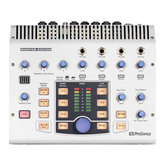
NTRO OLS & & CO ONNE ECTIO 3.1 FR RONT PAN NEL LAYO 3.1.1 Talkback • Talkback m microphone. T The built-in ta alkback microp phone is an el ectret conden ser microphon ne and is positione ed just above t he Talkback L Level knob. -
Page 17: Headphones
NTRO OLS & & CO ONNE ECTIO 3.1.2 Headphon • Phones. C onnects headp hones to the M Monitor Statio on’s four headp phone amplifie ers. • Level. Adj usts the outpu ut level of the a associated hea adphone amplif fier. -
Page 18: Source Control
CONTROLS & CONNECTION 3.1.4 Source Control • Main Source. Sets the Main bus’ input sources. The Main bus is the source for the Speaker outputs, Main L/R outputs and any headphone amplifiers whose source is set to ‘Main’. By default, the Main and Cue Source buttons are in Input Sum mode and can all be selected simultaneously. -
Page 19: Speaker Control
NTRO OLS & & CO ONNE ECTIO 3.1.5 Speaker C Control • Speaker Le evel Adjust. F Fine tunes the output level of f each stereo o output pair. T The optimum le evel of these knob s fully clockw wise (Unity Ga ain). -
Page 20: Main Level Control
NTRO OLS & & CO ONNE ECTIO 3.1.6 Main Leve el Control • Main Leve l. Adjusts the output level o of the active Sp peaker sets (A A, B and C). • Mono. Co onverts the ste ereo Main bu us source to a a mono signal l (does not af... -
Page 21: Back Panel Layout
CONTROLS & CONNECTION 3.2 BACK PANEL LAYOUT 3.2.1 Inputs • Talkback Mic. Connects a dynamic microphone to the built-in talkback microphone preamplifier. • ST1. Connects a stereo source to the Stereo 1 input bus. • ST2. Connects a stereo source to the Stereo 2 input bus. •... -
Page 22: Outputs
C. Connects the Main-Speaker C bus to a stereo device. The Speaker C L/R outputs are only active when the Speaker C button is active. 3.2.3 Power 16VAC 10Watts Designed by PreSonus in the USA. M anufactured in PRC. • AC Power Input. Connects the Monitor Station’s included 16 VAC power supply. •... -
Page 23: Technical Information
TECHNICAL INFORMATION 4.1 FREQUENTLY ASKED QUESTIONS Why can’t I hear the talkback microphone? • Remember, only headphones with a Phones Source of ‘CUE’ can hear the talkback microphone. • Connect and/or calibrate your talkback microphone according to section 2.1.7. • Verify your external mic does not require phantom power. -
Page 24: Troubleshooting
Please note that many technical issues can arise when connecting different components in a studio environment. PreSonus can only provide support for issues directly related to the Monitor Station Studio Control Center. It may be necessary to contact the manufacturer(s) of your other studio equipment to obtain additional technical support. -
Page 25: Specifications
TECHNICAL INFORMATION 4.3 SPECIFICATIONS Audio Inputs Talkback Microphone Gain Range ........................+15 to +55 dB Internal Microphone Type ........................electret condenser Sensitivity ..........................-42 dB External Input Type ....................... XLR Female Balanced Input Impedance (Balanced) ....................1200 Ω Maximum Gain ........................50 dB Maximum Input Level ...................... - Page 26 Input Connector Type .......... Barrel, 5.5 mm outside diameter, 2.1 mm inside diameter Monitor Station Input Voltage Range ..................... 16 VAC Power Requirements (Continuous) ....................... 10W As a commitment to constant improvement, PreSonus Audio Electronics, Inc. reserves the right to change any specification stated herein at any time without notification.
-
Page 27: Block Diagram
TECHNICAL INFORMATION 4.4 BLOCK DIAGRAM Le ft I npu t B us C ue Inp ut Bu s M a in In pu t Bu s C ue Out put Bu s Cu e Outp ut Bu s Ma in Ou tpu t B us M ain O utp ut Bus CUE OUTPUT MAIN OUTPUT...
Need help?
Do you have a question about the MONITOR STATION - V1.0 and is the answer not in the manual?
Questions and answers