PRESONUS STUDIO CHANNEL - V1.1 User Manual
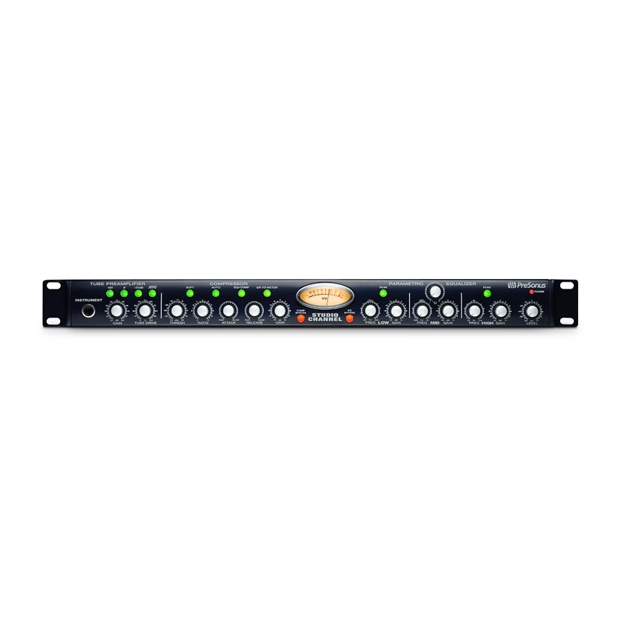
Vacuum tube channel strip
Hide thumbs
Also See for STUDIO CHANNEL - V1.1:
- User manual (25 pages) ,
- Manual (16 pages) ,
- Datasheet (2 pages)

Related Manuals for PRESONUS STUDIO CHANNEL - V1.1


Summary of Contents for PRESONUS STUDIO CHANNEL - V1.1
- Page 1 STUDIO CHANNEL Vacuum Tube Channel Strip User’s Manual Version 1.1 © 2008, PreSonus Audio Electronics, Inc. All Rights Reserved.
- Page 2 Some states do not allow limitations on how long an implied warranty lasts, so the above limitation may not apply to you. In no event will PreSonus be liable for...
-
Page 3: Table Of Contents
TABLE OF CONTENTS 1 OVERVIEW 1.1 Introduction ............................3 1.2 Features ..............................4 1.3 What is in the Box ..........................5 2 CONTROLS & CONNECTIONS 2.1 Front Panel Layout ..........................6 2.1.1 Tube Microphone Preamp ......................... 6 2.1.2 Compressor ............................7 2.1.3 Parametric EQ .......................... -
Page 5: Overview
OVERVIEW 1.1 INTRODUCTION Thank you for purchasing the PreSonus Studio Channel. PreSonus Audio Electronics has designed the Studio Channel utilizing high-grade components to ensure optimum performance that will last a lifetime. The Studio Channel is a professional channel strip combining Class A tube preamplifier, VCA-based compressor and three- band parametric equalizer perfect for the professional and project studio. -
Page 6: Features
The Studio Channel has everything needed to deliver big tone. The preamplifier stage of the Studio Channel is based on the award winning PreSonus BlueTube preamplifier with a high output 12AX7 vacuum tube operating on voltages double than all other preamplifiers in its class. It delivers high headroom and big tone, featuring dual control Gain and Tube Drive to create a wide range of sounds. -
Page 7: What Is In The Box
OVERVIEW 1.3 WHAT IS IN THE BOX Your Studio Channel package contains the following: Studio Channel 16VAC 1000mA Power Supply PreSonus Warranty Card | PreSonus 2007... -
Page 8: Controls & Connections
“blues harp” harmonica sound. 48 Volt Phantom Power. This button enables phantom power to the XLR input. XLR connector wiring for Phantom Power Pin 1 = GND Pin 2 = +48V Pin 3 = +48V | PreSonus 2007... -
Page 9: Compressor
Gain Make Up. When compressing a signal, gain reduction usually results in an overall reduction of level. The gain control allows you to restore the loss in level due to compression and readjust the volume to the pre-compression level (if desired). You can adjust the Gain Make Up from -10 to +10 | PreSonus 2007... -
Page 10: Parametric Eq
EQ. You can adjust the center frequency from 200 to 3 kHz. Mid Band Gain. Sets the Gain attenuation or boost of the Q. The level of the center frequency can be set between -10 and +10 dB. | PreSonus 2007... -
Page 11: Master And Vu Meter
Master Level. Adjust the overall output volume of the Studio Channel VU Meter. The analog VU meters the output level of your Studio Channel. When the GR>Meter button in the compressor section is enabled, the VU meter will show the amount of Gain Reduction. | PreSonus 2007... -
Page 12: Back Panel Layout
2.2 BACK PANEL LAYOUT Microphone Pre-Amplifier. Your Studio Channel is equipped with a custom designed PreSonus microphone preamplifier for use with all types of microphones including dynamic, condenser and ribbon. Line Level Input. The Studio Channel also features a balance line level input to connect synthesizers, amp modelers, etc. -
Page 13: Operation
– usually beyond repair. Regardless of the microphone type you are using, we recommend reading your microphone’s user’s manual thoroughly before engaging phantom power or if any other usage questions may arise. | PreSonus 2007... -
Page 14: A Brief Tutorial On Dynamics Processing
What follows is an excerpt from brief tutorial on dynamics processing written by PreSonus President and Chief Technical Officer, Jim Odom. It is included to help you get the most out of your Studio Channel. This tutorial will take you through the basics of dynamics processing as well as explain the various types of dynamics processors. -
Page 15: Types Of Dynamic Processing
As the compression threshold is lowered, more and more of the input signal is compressed (assuming a nominal input signal level). Care must be taken not to ‘over compress’ a signal. Too much compression destroys the acoustic | PreSonus 2007... - Page 16 How fast the gate closes is determined by the release. How much the gate attenuates the unwanted signal while closed is determined by the range. | PreSonus 2007...
-
Page 17: Vocabulary Of Dynamics Processing
Gain Makeup. When compressing a signal, gain reduction usually results in an overall reduction of level. The gain control allows you to restore the loss in level due to compression. (Like readjusting the volume.) | PreSonus 2007... - Page 18 The gate range is the amount of gain reduction that the gate closes down to. Therefore, if the range is set at 0dB, there will be no change in the signal as it crosses the threshold. If the range is set to -60dB, the signal will be gated (reduced) by 60dB, etc. | PreSonus 2007...
-
Page 19: General Compression Setting Suggestions
OPERATION 3.2.4 General Compression Setting Suggestions The following are compression presets used in the PreSonus BlueMax. We have included them as a jumping off point for setting up compression on your Studio Channel. Vocals Soft. This is an easy compression with a low ratio setting for ballads allowing a wider dynamic range. - Page 20 0.002mS 85mS Orchestral. Use this setting for string pads and other types of synthesized orchestra parts. It will decrease the overall dynamic range for easier placement in the mix. Threshold Ratio Attack Release 3.3dB 2.5:1 1.8mS 50mS | PreSonus 2007...
- Page 21 This is a setting for making the compressor pump in a desirable way. This effect is good for snare drums to increase the length of the transient by bringing the signal up after the initial spike. It is very contemporary. Threshold Ratio Attack Release 1.9:1 0.001mS | PreSonus 2007...
-
Page 22: Equalizers
4 kHz. In this example, you would use a broad Q boosted in the low frequency band centered at 100Hz and a narrow Q boosted at 4 kHz. In this way you are accentuating the best and downplaying everything else this particular kick drum has to offer. | PreSonus 2007... -
Page 23: How To Find The Best And Leave The Rest
15 minutes is not the right choice, move on. Never be afraid of taking a risk. The best EQ tricks were found by mad scientists of sound. “Playing” applies to engineers as well as musicians. | PreSonus 2007... -
Page 24: To Boost Or Not To Boost
Brilliance 15 kHz Horns 1 kHz Honky 8-12 kHz Big Sound 120 Hz and below Muddy 2 kHz Clarity String section 3 kHz Shrill 2 kHz Clarity 120 Hz and below Muddy 400-600 Hz Lush and full | PreSonus 2007... - Page 25 OPERATION Table 2 | PreSonus 2007...
-
Page 26: Application Settings
COMPRESSOR SETTINGS THRESH RATIO GAIN SOFT BYPASS ATTACK RELEASE -18 dB + 1 dB Fast EQ SETTINGS HIGH EQ>COMP PEAK GAIN FREQ GAIN FREQ PEAK GAIN FREQ 0 dB +2 dB 2.2 kHz +4 dB 9 kHz | PreSonus 2007... - Page 27 2.5 kHz Snare COMPRESSOR SETTINGS THRESH RATIO GAIN SOFT BYPASS ATTACK RELEASE -22 dB +4 dB EQ SETTINGS HIGH EQ>COMP PEAK GAIN FREQ GAIN FREQ PEAK GAIN FREQ 0 dB +2 dB 1kHz -2 dB 20 kHz | PreSonus 2007...
- Page 28 Drum Overheads COMPRESSOR SETTINGS THRESH RATIO GAIN SOFT BYPASS ATTACK RELEASE -22 dB +4 dB Fast EQ SETTINGS HIGH EQ>COMP PEAK GAIN FREQ GAIN FREQ PEAK GAIN FREQ -4 dB 40 Hz 0 dB +2 dB 20 kHz | PreSonus 2007...
-
Page 29: Technical Information
Output Connectors ................... XLR Balanced and ¼” TRS Balanced/Unbalanced Output Impedance ..............................51 Ω Metering (Output level) ..................... Analog VU (-20 dBu to +6 dBu) Metering (Gain Reduction) ......................Analog VU -20 dB to 0 dB Output Headroom ..............................+22 dBu | PreSonus 2007... - Page 30 Size ..................................1U Rack Dimensions ............................19” x 1.75” x 5.5” Weight ..................................5 lbs As a commitment to constant improvement, PreSonus Audio Electronics, Inc. reserves the right to change any specification stated herein at any time without notification. | PreSonus 2007...
Need help?
Do you have a question about the STUDIO CHANNEL - V1.1 and is the answer not in the manual?
Questions and answers