Table of Contents
Advertisement
Quick Links
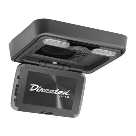
9 9 " " ( ( 1 1 6 6 : : 9 9 ) )
O O v v e e r r h h e e a a d d V V i i d d e e o o
M M o o n n i i t t o o r r / / D D V V D D P P l l a a y y e e r r
M M O O D D E E L L O O H H D D 9 9 0 0 1 1
© 2005 Directed Electronics, Inc. N82901 03-05
O O W W N N E E R R ' ' S S G G U U I I D D E E
I I N N S S T T A A L L L L A A T T I I O O N N G G U U I I D D E E
Advertisement
Table of Contents

Subscribe to Our Youtube Channel
Related Manuals for Directed Video OHD901


Summary of Contents for Directed Video OHD901
- Page 1 M M O O D D E E L L O O H H D D 9 9 0 0 1 1 © 2005 Directed Electronics, Inc. N82901 03-05 O O W W N N E E R R ’ ’ S S G G U U I I D D E E...
- Page 2 N N O O N N - - T T R R A A N N S S F F E E R R A A B B L L E E L L I I M M I I T T E E D D O O N N E E Y Y E E A A R R C C O O N N S S U U M M E E R R W W A A R R R R A A N N T T Y Y Directed Electronics, Inc. (Directed) promises to the original purchaser that the new automotive video...
-
Page 3: Table Of Contents
B B a a s s i i c c F F u u n n c c t t i i o o n n s s ....................2 2 3 3 © 2005 Directed Electronics, Inc. - Page 4 S S p p e e c c i i f f i i c c a a t t i i o o n n s s ....................4 4 1 1 © 2005 Directed Electronics, Inc.
- Page 5 DISTRACT THE DRIVER OR INTERFERE WITH THE SAFE OPERATION OF THE VEHICLE, AND MAY ALSO VIOLATE STATE LAW. DIRECTED ELECTRONICS, INC. DISCLAIMS ANY LIABILITY FOR ANY BODILY INJURY, INCLUDING FATALITIES, OR PROPERTY DAMAGE THAT MAY RESULT FROM ANY IMPROPER OR UNINTENDED USES OF THIS PRODUCT.
-
Page 6: While Driving
This unit is intended for use in the rear seat area only. It is illegal in some jurisdictions to install the unit in a location that would allow the driver to view it while driving. Power Harness DIN Cable Domelight Harness Mounting Trim Bezel A/V Cable for DVD Player AC/DC Adapter for DVD Player © 2005 Directed Electronics, Inc. -
Page 7: Installation
N N O O T T E E : : If the internal temperature of the vehicle is higher than the normal oper- ating temperature, please allow the vehicle to cool down (or warm up) prior to operating the unit. © 2005 Directed Electronics, Inc. -
Page 8: Picture Quality
Your product warranty will not be validated if your warranty registration is not returned. Make sure you receive the warranty registration from your dealer. It is also necessary to keep your proof of pur- chase, which reflects that the product was installed by an authorized dealer. © 2005 Directed Electronics, Inc. -
Page 9: Door Light On/Off
The menu will exit if no action is taken within a few seconds. DOWN Button—Used in conjunction with the MENU button to scroll down (or decrease) the menu setting. IR Receiver—Infrared receiver which receives commands from the remote control. © 2005 Directed Electronics, Inc. - Page 10 10. PLAY/PAUSE—When pressed pauses the playback until pressed again. 11. STOP—Halts playback. If the Play button is pressed the playback will continue from where stopped. If the Stop button is pressed twice, playback will now start from the beginning. © 2005 Directed Electronics, Inc.
- Page 11 Only 1 memory card can be inserted into the player at a time. * These buttons are used to navigate through the menus on the screen and then use the Enter but- ton to select the option. © 2005 Directed Electronics, Inc.
- Page 12 VOL Control—Controls the volume to the phone jack output. PHONE Jack—An optional headphone set can be connected here. A/V OUT Jack—Audio/video output jack. DC 12V Jack—Input power. IR Receiver—For receiving commands from the remote control. PHONE A/V OUT DC 12V © 2005 Directed Electronics, Inc.
- Page 13 Slide the player towards the LCD screen until the lock/unlock button latches. N N O O T T E E : : If the DVD player doesn’t power up correctly, remove the player (see instruc- tions below) and then re-install. © 2005 Directed Electronics, Inc. Logo Side...
- Page 14 Insert DVD Player and then slid down until unit locks. Lock/Unlock Electrical Button Connector © 2005 Directed Electronics, Inc.
- Page 15 Press the Image button on the remote control to access the different screen modes. The last mode set is displayed on the screen. Each time the Mode button is pressed, the screen switches in the following sequence. © 2005 Directed Electronics, Inc.
- Page 16 12. Console MENU 13-15. Numeric 28. ANGLE 29. SUBTITLE (on/off) 30. DOWN (Cursor) 31. AUDIO 32. ZOOM (2, 3, 4, 1/2, 1/3, 1/4, OFF) 33. F.REV (Fast Reverse) 34. PLAY/PAUSE 35. F.FWD (Fast Forward) 36. SLOW © 2005 Directed Electronics, Inc.
- Page 17 AV1 or AV2 source at the switch-box. The IR signals are compatible with models DV2602, DV2605 DVD players, and TV100 tuner. * These buttons are for use only with the TV tuner (model TV100). © 2005 Directed Electronics, Inc. 37. BACK 38. STOP 39.
- Page 18 1. Press OPEN at the upper right corner to open the door. 2. Load with the recorded side (the shiny side) facing up. With double-sided discs, load with the Remote Controller + side Battery Latch Battery Holder © 2005 Directed Electronics, Inc.
- Page 19 1. Press OPEN at the upper right corner to open the door. 2. Remove the disc. (Avoid touching the recorded surface.) 3. Push to close the door, until you hear a click sound from the door mechanism. © 2005 Directed Electronics, Inc.
- Page 20 N N o o t t e e : : The ignition key must be in the Accessory or Ignition position in order for the monitor to have power. Use this portion of the screen for opening, closing, and positioning. Open Pos ition © 2005 Directed Electronics, Inc.
- Page 21 The FM frequency setting allows the monitor to transmit audio to the vehicle’s radio. Use a frequency that is not interfered with from a local broadcast station. This setting also has an OFF position. © 2005 Directed Electronics, Inc. button on either the remote or the Power button on the left button on the remote to activate →...
- Page 22 C C O O U U R R T T E E S S Y Y L L I I G G H H T T O O N N / / O O F F F F Activate this switch on the monitor to control the dome light illumination. © 2005 Directed Electronics, Inc.
-
Page 23: Dvd Playback
FF 4X Press "P P L L A A Y Y " button, the speed will go back to standard. © 2005 Directed Electronics, Inc. button or the monitor’s POWER button to button to put the unit into standby mode. - Page 24 "PLAY" will momentarily display on the LCD. The button is pressed,the playback will stop. “PRE STOP” will button to continue playback from the point where button is pressed twice. "STOP" will display on the LCD. Press © 2005 Directed Electronics, Inc.
- Page 25 For example if a memory stick contains MP3 and JPEG files but does not contain any video files, the music and camera icons will appear white, but the video icon will appear dark. If a file is playing or displaying, the icon associated with that file will turn RED. © 2005 Directed Electronics, Inc.
- Page 26 For SVCD, VCD, or CD the programming menu below displays. These formats do not have Track and Chapter. PROG [--] [--] [--] [--] --:-- --:-- --:-- --:-- --:-- --:-- --:-- --:-- PLAY CLEAR [--] [--] [--] [--] [--] [--] [--] [--] PLAY CLEAR --:-- --:-- --:-- --:-- [--] [--] [--] [--] © 2005 Directed Electronics, Inc.
- Page 27 Each press of the AUDIO button will cycle the DVD through each language available. N N O O T T E E : : The audio function works only for discs that have multiple audio soundtracks. © 2005 Directed Electronics, Inc. icon along with “x/y” will appear.
- Page 28 (D) Press the Arrow buttons to highlight the Exit Setup option, then press Enter or Setup again to exit Setup Menu. icon will appear along with arrow button © 2005 Directed Electronics, Inc.
-
Page 29: Screen Saver
2 2 . . S S C C R R E E E E N N S S A A V V E E R R ON: Choose this setting to activate the screen saver. OFF: Choose this setting to cancel the screen saver. © 2005 Directed Electronics, Inc. ------... -
Page 30: Password
Refer to the Password discussion above. ). If you want to access and ). To change the password, you ------ ------ ------ ------ 2 PG 3 PG -1 3 5 NC -1 7 6 ALL © 2005 Directed Electronics, Inc. -
Page 31: Osd Language
Highlight the AUDIO LANG option, and press the Arrow buttons to choose the audio language you prefer. Press Enter to confirm. You can select English, Japan, French, Spanish, Portuguese, Latin, German or Chinese. © 2005 Directed Electronics, Inc. -
Page 32: Electrical Connections
Please refer to the electrical connection diagrams of this product prior to installation to avoid improper connection. Use proper connectors and insulation to prevent electrical damage to the unit. ------ ------ © 2005 Directed Electronics, Inc. - Page 33 Gray This wire connects to the (-) door trigger. © 2005 Directed Electronics, Inc. F F u u n n c c t t i i o o n n F F u u n n c c t t i i o o n n...
- Page 34 Audio - Left (Output) F F u u n n c c t t i i o o n n Video - In (V-IN 1) Video - In (V-IN 2) Video - Out (V-OUT 1) © 2005 Directed Electronics, Inc.
- Page 35 T T Y Y P P I I C C A A L L W W I I R R I I N N G G D D I I A A G G R R A A M M Wireless Headphones YELLOW–12V Constant GRAY (-) Door Trigger © 2005 Directed Electronics, Inc. SOURCE 2 BLACK–Ground RED–Ignition YELLOW–12V Constant BLACK–Ground...
-
Page 36: Dome Light Wiring
T T O O M M O O U U N N T T I I N N G G T T H H E E B B R R A A C C K K E E T T , , T T O O P P R R E E C C L L U U D D E E P P E E N N E E T T R R A A T T I I O O N N O O F F T T H H E E V V E E H H I I C C L L E E ’ ’ S S R R O O O O F F . Positive Negative Trigger Door Trigger Door Switch Switch Grey: Door Switch Yellow: +12V Black: Ground Dome Light Wiring © 2005 Directed Electronics, Inc. - Page 37 N N O O T T E E : : Make sure you keep the ground wire of the monitor and video source as short as possible to prevent unwanted audio noise pickup from the vehicle’s systems. © 2005 Directed Electronics, Inc. Roof Beam Support...
- Page 38 S S y y s s t t e e m m W W i i r r i i n n g g D D i i a a g g r r a a m m E E x x a a m m p p l l e e AUDIO AMPLIFIER YELLOW BATTERY (+12V) Video In BLACK (GROUND) Power RED (ACC) TV Tuner YELLOW BLACK (GROUND) +12V CONSTANT GRAY (DOOR SWITCH) IR Transmitter © 2005 Directed Electronics, Inc.
- Page 39 W W i i t t h h a a w w i i d d e e s s c c r r e e e e n n 1 1 6 6 : : 9 9 m m o o n n i i t t o o r r , , I I h h a a v v e e b b l l a a c c k k b b a a r r s s o o n n t t h h e e s s c c r r e e e e n n Change the TV display mode to "Wide". © 2005 Directed Electronics, Inc.
- Page 40 U U n n i i t t d d o o e e s s N N O O T T D D i i s s p p l l a a y y o o r r O O p p e e r r a a t t e e C C o o r r r r e e c c t t l l y y Press Reset button located on the monitor along side the DVD player. This resets all of the system, except for the Password and Parental Level setting. © 2005 Directed Electronics, Inc.
- Page 41 Mass Operating Temperature Operating Humidity N N O O T T E E : : Specifications and design are subject to change without notice. © 2005 Directed Electronics, Inc. Semiconductor laser NTSC, PAL DVD Video (PCM@ 96kHz) 20 Hz - 40 kHz ± 1dB DVD Video (PCM@ 48kHz) 20 Hz - 20 kHz ±...
- Page 42 Directed is ISO 9001 registered. Quality Directed Electronics products are sold and serviced throughout North America and around the world. Call ( ( 8 8 0 0 0 0 ) ) 2 2 7 7 4 4 - - 0 0 2 2 0 0 0 0 for more information about our products and services.
Need help?
Do you have a question about the OHD901 and is the answer not in the manual?
Questions and answers