
Related Manuals for ASROCK 775I48


Summary of Contents for ASROCK 775I48
- Page 1 775i48 User Manual Version 1.0 Published October 2004 Copyright©2004 ASRock INC. All rights reserved.
- Page 2 (including damages for loss of profits, loss of business, loss of data, interruption of business and the like), even if ASRock has been advised of the possibility of such damages arising from any defect or error in the manual or product.
-
Page 3: Table Of Contents
2.1 Screw Holes ..............10 2.2 Pre-installation Precautions ..........10 2.3 CPU Installation ..............11 2.4 Installation of CPU Fan and Heatsink ........13 2.5 Installation of Memory Modules (DIMM) ......14 2.6 Expansion Slots (PCI and AGP Slots) ......... 15 2.7 Jumpers Setup .............. - Page 4 4.2 Support CD Information ..........36 4.2.1 Running Support CD ..........36 4.2.2 Drivers Menu ............36 4.2.3 Utilities Menu ............36 4.2.4 ASRock “PC-DIY Live Demo” Program ....36 4.2.5 “LGA 775 CPU Installation Live Demo” Program..36 4.2.6 Contact Information ..........36...
-
Page 5: Introduction
ASRock’s commitment to quality and endurance. In this manual, chapter 1 and 2 contain introduction of the motherboard and step-by- step guide to the hardware installation. Chapter 3 and 4 contain the configuration guide to BIOS setup and information of the Support CD. -
Page 6: Specifications
1.2 Specifications Platform: ATX Form Factor: 12.0-in x 7.2-in, 30.5 cm x 18.3 cm CPU: 775-Pin Socket ® ® ® supporting Intel Pentium 4 / Celeron processor (in 775-land LGA package) Chipsets: North Bridge: ® Intel 848P chipset, FSB @ 800 / 533 MHz, Max. - Page 7 To improve heat dissipation, remember to spray thermal grease between the CPU and the heatsink when you install the PC system. Do NOT use a 3.3V AGP card on the AGP slot of this motherboard! It may cause permanent damage! ®...
-
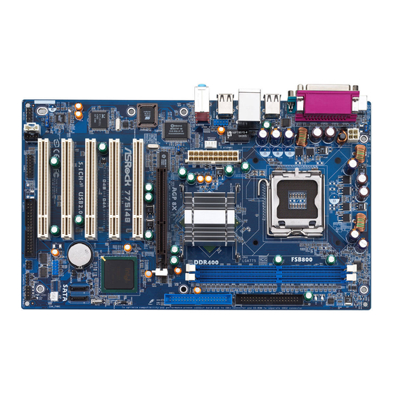
Page 8: Motherboard Layout
Infrared Module Connector (IR1) 775-Pin CPU Socket Floppy Connector (FLOPPY1) North Bridge Controller Game Connector (GAME1) 184-pin DDR DIMM Slots (DDR DIMM1- 2) Internal Audio Connector: CD1 (Black) Secondary IDE Connector (IDE2, Black) Internal Audio Connector: AUX1 (White) Primary IDE Connector (IDE1, Blue) Front Panel Audio Connector (AUDIO1) AGP Slot (1.5V_AGP1) -
Page 9: Asrock I/O Plus
1.4 ASRock I/O Plus Parallel Port USB 2.0 Ports (USB01) RJ-45 Port USB 2.0 Ports (USB23) Line In (Light Blue) Serial Port: COM1 Line Out (Lime) PS/2 Keyboard Port (Purple) Microphone (Pink) PS/2 Mouse Port (Green) Shared USB 2.0 Ports (USB45) -
Page 10: Installation
Chapter 2 Installation 775i48 is an ATX form factor (12.0" x 7.2", 30.5 x 18.3 cm) motherboard. Before you install the motherboard, study the configuration of your chassis to ensure that the motherboard fits into it. Make sure to unplug the power cord before installing or removing the motherboard. -
Page 11: Cpu Installation
Before you insert the 775-LAND CPU into the socket, please check if the CPU surface is unclean or if there is any bent pin on the socket. Do not force to insert the CPU into the socket if above situation is found. - Page 12 PnP cap to assist in removal. It is recommended to use the cap tab to handle and avoid kicking off the PnP cap. Step 4. Close the socket: Step 4-1.
-
Page 13: Installation Of Cpu Fan And Heatsink
CPU and the heatsink to improve heat dissipation. Ensure that the CPU and the heatsink are securely fastened and in good contact with each other. Then connect the CPU fan to the CPU_FAN connector (CPU_FAN1, see page 8, No. -
Page 14: Installation Of Memory Modules (Dimm)
DIMMs or the system components. Step 1. Unlock a DIMM slot by pressing the retaining clips outward. Step 2. Align a DIMM on the slot such that the notch on the DIMM matches the break on the slot. notch break... -
Page 15: Expansion Slots (Pci And Agp Slots)
Please do NOT use a 3.3V AGP card on the AGP slot of this motherboard! It may cause permanent damage! For the voltage information of your graphics card, please check with the graphics card vendors. -
Page 16: Jumpers Setup
Note: To select +5VSB, it requires 2 Amp and higher standby current provided by power supply. (see p.8 No. 23) (see p.8 No. 23) Note: If the jumpers JL1 and JR1 are short, both the front panel and the rear panel audio connectors can work. Clear CMOS (CLRCMOS0, 2-pin jumper) 2-pin jumper (see p.8 No. -
Page 17: Onboard Headers And Connectors
FLOPPY1 Pin1 (see p.8 No. 18) the red-striped side to Pin1 Note: Make sure the red-striped side of the cable is plugged into Pin1 side of the connector. Primary IDE connector (Blue) Secondary IDE connector (Black) (39-pin IDE1, see p.8 No. 7) (39-pin IDE2, see p.8 No. - Page 18 USB 2.0 Header ASRock I/O Plus accommo- USB_PWR dates 6 default USB 2.0 ports. If (9-pin USB67) DUMMY those USB 2.0 ports on the I/O (see p.8 No. 14) panel are not sufficient, this USB 2.0 header is available to...
- Page 19 CPU Fan Connector Please connect a CPU fan cable to this connector and match (4-pin CPU_FAN1) the black wire to the ground pin. (see p.8 No. 27) ATX Power Connector Please connect an ATX power supply to this connector.
-
Page 20: Serial Ata (Sata) Hard Disks Installation
STEP 3: Connect one end of the SATA data cable to the motherboard’s primary SATA connector (SATA1). STEP 4: Connect the other end of the SATA data cable to the primary SATA hard disk. If you just want to install only one SATA HDD, the installation process is complete at this step. -
Page 21: Bios Setup Utility
Power-On-Self-Test (POST) to enter the BIOS SETUP UTILITY, otherwise, POST will continue with its test routines. If you wish to enter the BIOS SETUP UTILITY after POST, restart the system by pressing <Ctl> + <Alt> + <Delete>, or by pressing the reset button on the system chassis. -
Page 22: Navigation Keys
To save changes and exit the BIOS SETUP UTILITY <ESC> To jump to the Exit Screen or exit the current screen 3.2 Main Screen When you enter the BIOS SETUP UTILITY, the Main screen will appear and display the system overview BIOS SETUP UTILITY Advanced... -
Page 23: Advanced Screen
3.3 Advanced Screen In this section, you may set the configurations for the following items: CPU Configuration, Chipset Configuration, ACPI Configuration, IDE Configuration, PCIPnP Configuration, Floppy Configuration, SuperIO Configuration, and USB Configuration. BIOS SETUP UTILITY Advanced H/W Monitor Boot Security... -
Page 24: Chipset Configuration
If it shows “Locked”, then the item Ratio CMOS Set- ting will be hidden. If you use the ratio value to time the CPU frequency, it will be equal to the core speed of the installed processor. - Page 25 DRAM Burst Length DRAM Burst length can be set as [8] or [4]. Memory Hole The default value of this item is [Disabled], or you may set the value of this item as [15MB-16MB]. Init. Graphic Adapter Priority This allows you to select [PCI/AGP] and [AGP/PCI] as the initial graphics adapter priority.
-
Page 26: Acpi Configuration
Use this item to enable or disable Ring-In signals to turn on the system from the power-soft-off mode. PCI Devices Power On Use this item to enable or disable PCI devices to turn on the system from the power-soft-off mode. PS/2 Keyboard Power On Use this item to enable or disable PS/2 keyboard to turn on the system from the power-soft-off mode. -
Page 27: Ide Configuration
When [Compatible Mode] is selected Combined Mode Option It allows you to select between [Pri IDE + SATA] and [SATA + Sec IDE]. If it is set to [Pri IDE + SATA], then the secondary IDE will not work. Likewise, if it is set to [SATA + Sec IDE], then the primary IDE will not work. - Page 28 [ARMD]: This is used for IDE ARMD (ATAPI Removable Media Device), such as MO. LBA/Large Mode Use this item to select the LBA/Large mode for a hard disk > 512 MB under DOS and Windows; for Netware and UNIX user, select [Disabled] to disable the LBA/Large mode.
-
Page 29: Pcipnp Configuration
Block (Multi-Sector Transfer) The default value of this item is [Auto]. If this feature is enabled, it will enhance hard disk performance by reading or writing more data during each transfer. PIO Mode Use this item to set the PIO mode to enhance hard disk performance by optimizing the hard disk timing. -
Page 30: Floppy Configuration
Use this item to enable or disable floppy drive controller. Serial Port Address Use this item to set the address for the onboard serial port or disable it. Configuration options: [Disabled], [3F8 / IRQ4], [2F8 / IRQ3], [3E8 / IRQ4], [2E8 / IRQ3]. - Page 31 Parallel Port Address Use this item to set the address for the onboard parallel port or disable it. Configuration options: [Disabled], [378], and [278]. Parallel Port Mode Use this item to set the operation mode of the parallel port. The default value is [ECP+EPP].
-
Page 32: Usb Configuration
“Auto” option will disable the legacy USB support. 3.4 Hardware Health Event Monitoring Screen In this section, it allows you to monitor the status of the hardware on your system, including the parameters of the CPU temperature, motherboard temperature, CPU fan speed, chassis fan speed, and the critical voltage. -
Page 33: Boot Screen
3.5 Boot Screen In this section, it will display the available devices on your system for you to config- ure the boot settings and the boot priority. BIOS SETUP UTILITY Main Advanced H/W Monitor Boot Security Exit Boot Settings Configure Settings during System Boot. -
Page 34: Boot Device Priority
CD/DVD drives. 3.6 Security Screen In this section, you may set or change the supervisor/user password for the system. For the user password, you may also clear it. BIOS SETUP UTILITY... -
Page 35: Exit Screen
BIOS SETUP UTILITY. Discard Changes and Exit When you select this option, it will pop-out the following message, “Dis- card changes and exit setup?” Select [OK] to exit the BIOS SETUP UTILITY without saving any changes. Discard Changes When you select this option, it will pop-out the following message, “Dis-... -
Page 36: Software Support
“LGA 775 CPU Installation Live Demo”. We hope you may check this live demo program before you start the installation of LGA 775 CPU in order to reduce the risks of CPU and motherboard damages caused by any improper handling. To see this Live ®...
Need help?
Do you have a question about the 775I48 and is the answer not in the manual?
Questions and answers